12-1 Digital input Plug-in Module Specifications
12-1-1 MB-4X
This is a digital input plug-in module for the MQ model. It can be expanded to two at most. The upper one is fixed to X16-X19, and the lower one is fixed to X20-X23. Its specifications and usage are the same as the M16X module. For details, please refer to M16X.
12-2 Digital output Plug-in Module Specifications
12-2-1 MB-4YT/MB-4YJ
This is a digital output plug-in module for the MQ model. It can be expanded to two at most. The upper one is fixed to Y16-Y19, and the lower one is fixed to Y20-Y23. Its specifications and usage are the same as the M16Y module. For details, please refer to M16YT/M16YJ.
12-3 High Speed Digital output Plug-in Module Specifications
12-3-1 MB-2PSOT
This is the pulse output plug-in module for the MQ model. It can be expanded to two at most. The upper one is fixed to PSO4 and PSO5; the lower one is fixed to PSO6 and PSO7.
Usage steps:
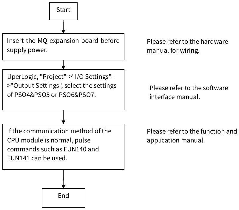
The software and instructions are used like the built-in HPSO output on the PLC host. Please refer to Chapter 9 Pulse Output and NC Positioning Control in the Function and Application Manual.
12-4 High Speed Digital Input Plug-in Module Specifications
12-4-1 MB-2HSC
This is a high-speed counting plug-in module for the MQ model. It can be expanded to two at most. The upper ones are fixed to HSC4 and HSC5; the lower ones are fixed to HSC6 and HSC7.
Usage steps:
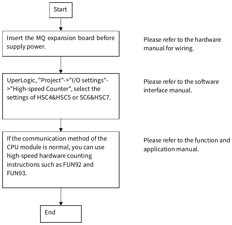
The software and instructions are used like the built-in HSC high-speed counter on the PLC host. Please refer to Chapter 8 High-speed Counter and Timer in the Function and Application Manual, Chapter 8-1 High-speed Counter.
12-5 Communication Plug-in Module Specifications
12-5-1 MB-CB2
This is an RS232 plug-in module for the MQ model. It can be expanded to two at most. The upper one is fixed to PORT3; the lower one is fixed to PORT4.
Usage steps:
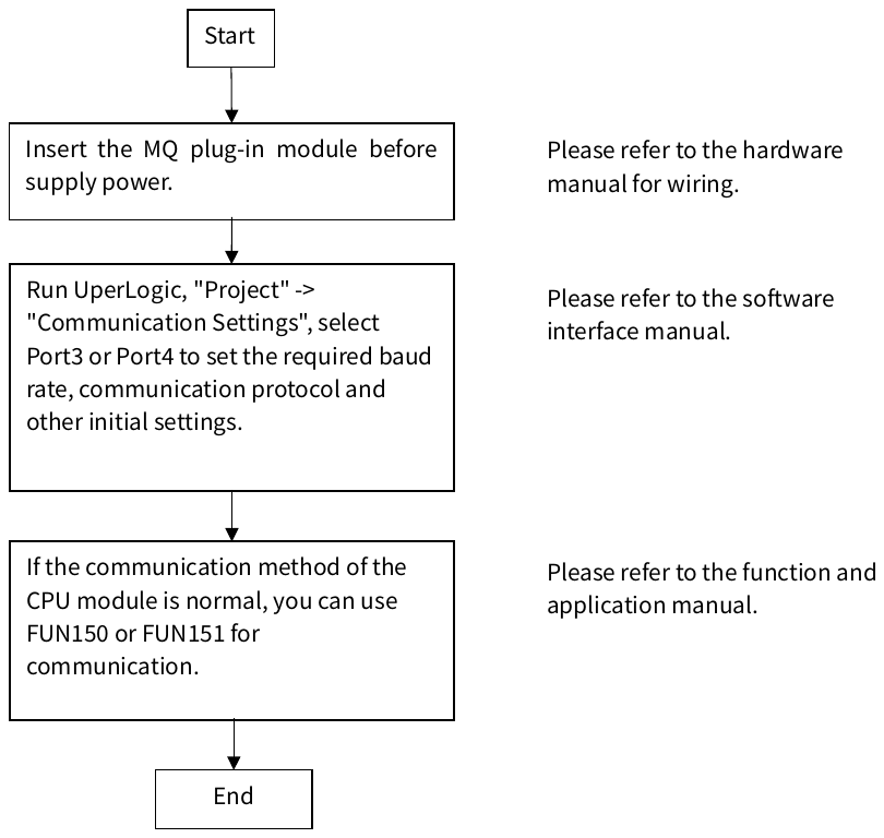
The software and instructions are used like the two RS485 built-in on the PLC host. Please refer to Chapter 10 Serial Communication in the Function and Application Manual.
12-5-2 MB-CB5
This is an RS485 plug-in module for the MQ model. It can be expanded to two at most. The upper one is fixed to PORT3; the lower one is fixed to PORT4.
Usage steps:
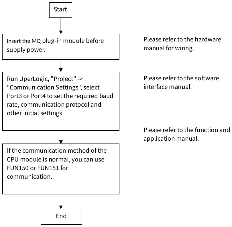
The software and instructions are used like the two RS485 built-in on the PLC host. Please refer to Chapter 10 Serial Communication in the Function and Application Manual.
12-5-3 MB-CBEQ
MB-CBEQ is a dedicated Ethernet communication expansion board for MQ series PLC main units. Through this expansion board, the PLC can communicate via Ethernet with controllers or computers on the network, and can simultaneously operate in both client and server modes.
This expansion board installs directly into the main unit’s internal expansion slots, taking up no space from the right-side ribbon cable connected expansion modules. The main unit provides upper and lower expansion slots, allowing up to two MB-CBEQ boards to be installed simultaneously, each with independent addressing.
FATEK M1 Slave, Modbus TCP Slave, and Modbus TCP Master are independent functions. There is no need to pre-assign an operating mode; all three can operate concurrently.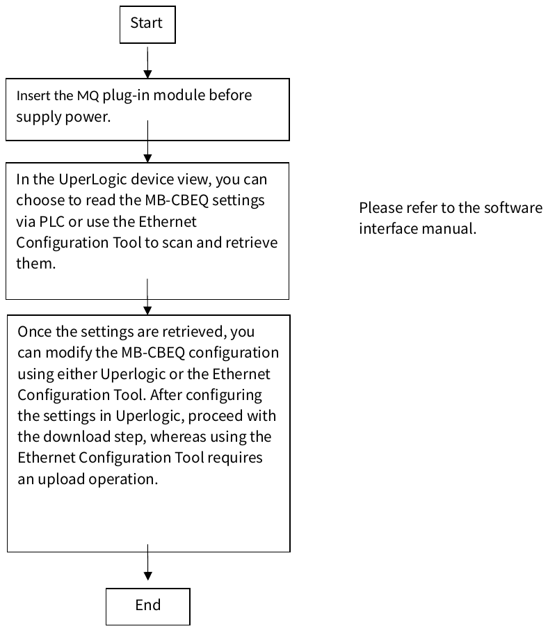
12-6 RTC Plug-in Module Specifications
12-6-1 MB-RTC
This is an RTC perpetual calendar plug-in module for the MQ model. The host does not have a built-in perpetual calendar and can be expanded to one at most.
Usage steps:
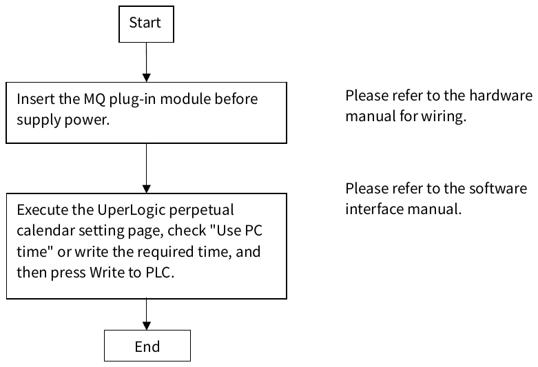
By setting with the software UperLogic, it allows users to set up the calendar time(RTC) without the need of using special M9179 relay and Ladder control function. The steps described below are the corresponding setting and operation methods:
Open the UperLogic and then connect it to the PLC that will be set.
In the upper left tool bar, click PLC-> PLC set -> RTC.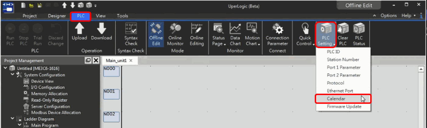
Figure 2 Selections of RTC Settings
After being selected, the following page will be exported.
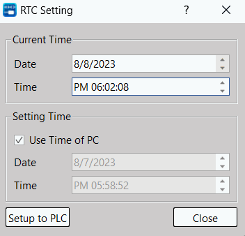
Figure 3 Window of RTC Settings
Adjust the time that will be set and then click the “Set to PLC” option.
Instructions and notice for the RTC setting window:
- “Current Time” column: The current time retrieved from PLC under online status.
- “Set Time” column: Tick “Use PC Time” and the PC time will be displayed in the lower-side column. Next, press the “Set to PLC” button and “Current Time” will be changed to current PC time.
- When cancelling the ticking of “Use PC Time”, you may change the “Date” and “Time” in the lower-side column as required. Next, press the “Set to PLC” button again and “Current PLC Time” will be changed to the time being set currently.
- When the PLC stops running, you cannot set the RTC and the picture below will appear.
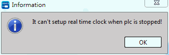
Figure 4 RTC setting is not available when the PLC stops running.
Tip: press ← → to switch chapters, Ctrl+K to search