4-1 Setting Retentive Memory
In addition to providing the project data and the system information, the PLC also allows users to retain important data register and digital output points. By achieving that, the retentive configuration shall be set up successfully as needed. In the meantime, we also provide the configuration of analog output register (OR), as well as the retentive range of every configurable device memory area.
4-1-1 Retentive Plan of Memory
Run function bar “Project” → “Memory setup”; or in project window, click→ “System configuration” → “Memory setup” twice and the memory setup window appears:
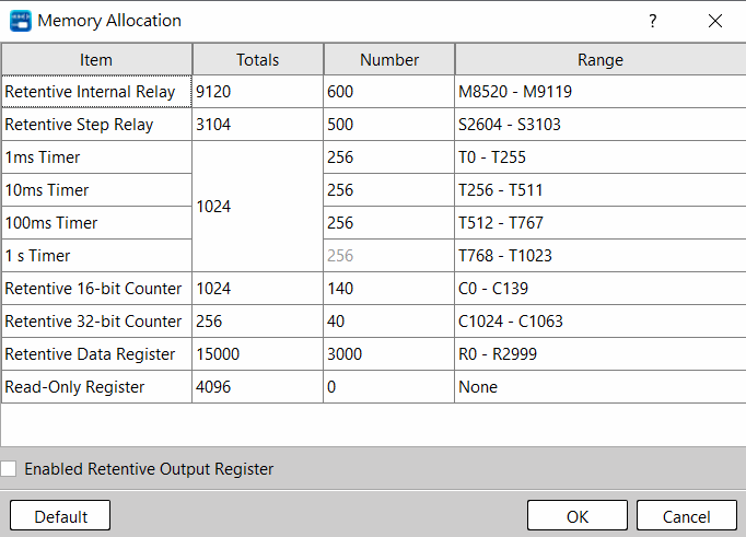
Figure 10 Configuration window of memory
Before shipping, all relevant setting has been properly arranged for things like Retentive or Non-retentive range of coils and registers, as well as the scope of read-only register. That is, we provide users with a default configuration.
In most applications, it is not required to change the default configuration. To cope with special or complicated applications, it also provides the UperLogic function in addition to the default configuration in order that the user may create his own setting or change the configuration. With “Preset” value, the user may return to the initial system setting status by pressing such button. After pressing “OK”, the current contact and register related information will be displayed to complete the memory configuration setting.
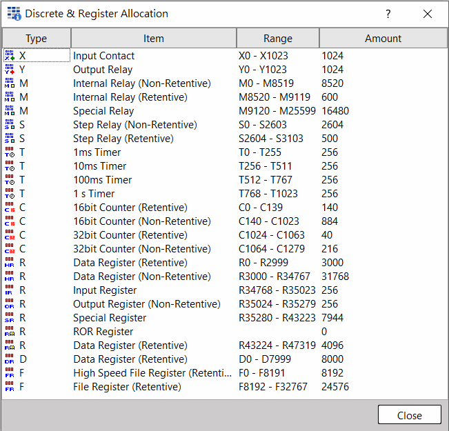
Figure 11 Discrete and Register Allocation
When restarting after shutdown or when setting the PLC from STOP→RUN, the Non-retentive replay or register will be cleared as “0”; however, the Retentive will maintain the original status (before shutdown or when STOP).
4-1-2 Setting the retentive output register
The amount of general output register (R35024~R35279) will not be retained after shutdown or under the operation STOP->RUN. Please check“Apply retentive output register”in the Figure 10 to enable the retention of this memory area.
4-1-3 Digital Output Retention
The general digital output contacts will not be retained after shutdown or under the operation STOP->RUN. The function can be unlocked in project window, click→ “System configuration” → “I/O configuration” and choose output setting to operate the function:
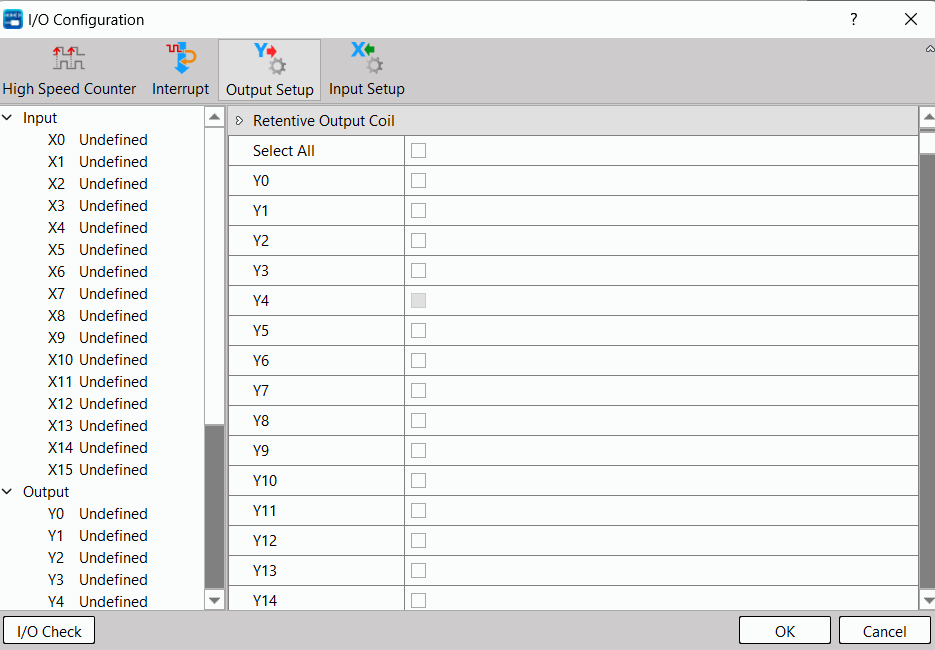
Figure 12 The setting of output shutdown retention
Tip: press ← → to switch chapters, Ctrl+K to search