With the two built-in RS-485 communication ports and the serial expansion module of the M-series CPU Unit users can connect and integrate with smart peripherals that have the same serial hardware communication interface through communication.
The FUN151 (CLINK) communication connection convenience command can specify the working mode of the communication port. There are 5 working modes, including Mode 0, 1, 2, 3, 4, and 5.
The following table shows the description of the command mode.
|
Item Type |
Transmission Rate |
Data Length |
Transmission Code |
Error Detection Method |
Command Processing Speed |
|
|
FUN151 (CLINK) |
FATEK M1 Communication Protocol (MD0) |
4.8Kbps ~ 921.6Kbps |
8 bits |
Binary Code |
Based on Protocols |
Scanning Time |
|
User-Defined Communication Protocol (MD1、2、4、5) |
7/8 bits |
|||||
|
FATEK High-Speed CPU Link (MD3) |
38.4kbps ~ 921.6Kbps |
|||||
FUN150(Modbus) communication connection command can specify the communication port to communicate with the Modbus Communication Protocols.
The following table is the description of the command mode:
|
Item Type |
Transmission Rate |
Data Length |
Transmission Code |
Error Detection Method |
Command Processing Speed |
|
|
FUN150 (MODBUS) |
Modbus RTU/ASCII |
4.8Kbps ~ 921.6Kbps |
8 bits |
Binary Code |
Modbus CRC |
Scanning Time |
10-1 Function of Serial Communication Port
M-Series CPU Unit comprises two RS485 software interfaces, Port 1 and Port 2. If it is not enough, you can install another communication module (CM) to expand the communication port interface to fourteen at most. (PORT1~PORT4 and HCM ports). Communication module (CM) has two interfaces of RS232 or RS485 to choose from. UperLogic software have communication drivers that conform to the "FATEK M1 Communication Protocols". If the hardware interface and communication parameters are consistent, Communication port can be connected by connecting to the communication port of the "standard interface". If there is no communication driver that conforms to this protocol, in addition to writing commands conforming to the " FATEK M1 Communication Protocols" format to communicate with the PLC, you can also use the most commonly used Modbus RTU/ASCII Protocols in the industry to communicate with the PLC. Port 1 and Port 2 are also defaulted as FATEK standard communication interface in the factory setting or system initialization of PLC. In order to meet the wide application and demand of communication connection, Port 1 and Port 2 not only provide FATEK standard communication interface. It also provides support for powerful communication convenience commands, allowing users to write the required application communication programs through the Ladder program, which can easily achieve the purpose of system integration and decentralized monitoring.
Additional Port3 and Port4 are only supported on the MQ series.
For details, please refer to the descriptions in the following chapters.
In M SERIES PLC, its software comprises two types of software interfaces. Listed below are the types of software interfaces that can be set through the respective port:
|
Type Option Software |
Communication port |
Remark |
|||
|
Port1 |
Port2 |
Port3 |
Port3 |
||
|
Standard Interface |
○ |
○ |
Fatek M1 Slave Modbus RTU/ASCII Slave |
||
|
Plugged-in Interface |
○ |
○ |
Fatek M1 Slave Modbus RTU/ASCII Slave * MQ only |
||
|
Ladder Function Interface |
○ |
○ |
○ |
○ |
The Port will be controlled by Ladder program. *Only Port 2 supports High-Speed CPU Link |
- Standard Interface:
Port1–Port2 can be set as this type of interface. In such interface, the Port is controlled by the standard communication drive program (using FATEK’s M SERIES PLC communication protocol or Modbus RTU/ASCII communication protocol) installed in the M SERIES PLC and it is termed as the “standard interface”. To communicate with the “standard interface”, the online operation will be allowed after meeting FATEK’s M-SERIES PLC communication protocol or Modbus RTU/ASCII communication protocol.
- Plugged-in Interface:
Only MQ-series PLC supports plugged-in interfaces, up to 2 ports, port 3 and port 4. The description of the function of this kind of interfaces is the same as standard interfaces.
- Ladder Function Interface:
Such type of interface can be selected by Port1–Port4. When operating on such type of interface, such Port will be controlled by Ladder commands (e.g., FUN94, FUN150 and FUN151). Through the Ladder program, the user will be allowed to control such Port.
Provided below is the description of function and application when these two communication ports of M SERIES PLC are operating under the aforesaid two types of interfaces.
10-1-1 Communication Port1~Port4
Functional specification
- Port 1 and Port 2 : RS485 interfaces with functional specification complying with EIA-RS485.
- Port 3 and Port 4 : RS232/485 interfaces with functional specification complying with RS-232 and EIA-RS485 respectively.
Basic usage
There are 2 types of software interface are selectable as follows:
➀ Standard interface:
Connectable to peripherals with RS485 interface, such as computer, UperLogic , HMI, SCADA, etc.
➁ Ladder diagram Program controlled interface:
User can control Port1~Port4 through the ladder diagram instructions; FUN151 (CLINK) command takes control of Port1~Port4 to establish connection with FATEK CPU Link or peripherals with RS485 interfaces; FUN150 (MBUS) command can turn Port1~Port4 into a master of Modbus RTU/ASCII communication protocol for connecting Slaves with this communication protocol.
Extended usage
- Under Standard interface, act as the Slave for multi-drop FATEK RS485.
- Under Ladder diagram program-controlled interface types, Port1~Port4 has the following functions:
➀ Use MD0 mode of FUN151 (CLINK) instruction to act as the master for FATEK CPU Link network.
➁ Use MD1 mode of FUN151 (CLINK) instruction to actively connect to intelligent peripherals equipped with this communication interface, such as other brands’ PLC, servo driver, temperature controller, inverter, message display, etc.
➂ Use FUN150 (MBUS) instruction to act as the Master for Modbus RTU/ASCII communication protocol to connect to peripherals with this communication protocol.
10-1-2 Description of Communication Functions
For the computer equipment to be able to communicate, hardware interface and organization software interface (i.e., communication protocol) communication parameters must be consistent between the sender and receiver. The same is true for PLC. After meeting the above three basic elements, PLC can communicate with PLC or other peripherals. These three aspects are described here.
Matching between hardware interface and mechanism
In order to meet the different needs of various peripheral devices, M-Series PLC can expand S232, RS485 communication interfaces are available. When using, please confirm whether the interface is consistent? If different communication interfaces are connected together, it may cause permanent damage to the hardware. Please also confirm whether the connected signal is correct? For example: TxD must be connected to RxD, RTS will be connected to CTS, RS232, RS485 are explained as follows:
Port 1 ~ Port 4 & HCM Ports
If you purchase a communication module (CM), you can expand one to twelve communication port interfaces, and the maximum number of communication port interfaces can be expanded to 14 (Port1 ~ Port2+ HCM ports), except for MQ-series PLC(Port1 ~ Port4).
Port1 ~ Port4 are defaulted to the "FATEK communication interface" in the factory setting or when the PLC system is initialized. For HCM ports, users need to select the mode by themselves, and they must go to the device view to configure the settings. In order to meet the wide application of communication connections According to the requirements, Port1 ~ Port4 not only provide FATEK standard communication interface, but also provide convenient communication commands with powerful functions, so that users can write the required application communication programs through Ladder commands, which can easily achieve system integration and decentralization. Purpose of monitoring.
Communication port interface of the communication module (CM) has two options: RS232+RS485 or RS485+RS485
- RS232 Communication interface
Each communication module (CM) provides one or two sets of RS232 communication interface (9 Pin D-sub female connector). For application, users can purchase a standard 9 Pin RS232 cable from a computer store, or use the following Make 9 Pin RS232 cable by yourself.
|
Signal Port Connector |
TXD |
RXD |
RTS |
CTS |
SG |
DTR |
DSR |
|
|
9Pin |
MALE |
3 |
2 |
7 |
8 |
5 |
4 |
6 |
|
FEMALE (HCM25 Module) |
2 |
3 |
8 |
7 |
5 |
6 |
4 |
|
M-Series PLC is not used.
9P D-sub female > 9P D-sub male RS232 communication cable :
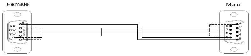
If you make RS232 cables by yourself and the definition of each pin is not clear, use a multimeter for measurement to determine TXD and RXD.
9 Pin connector: The pin 5 is SG;
Measure the pin 2 (red probe) and the pin 5 (black probe) with a multimeter. If it is approximately -9V, it means that the pin 2 is the transmission pin; If it is approximately 0V, it means that the pin 2 is the receiving pin.
Measure the pin 3 (red probe) and the pin 5 (black probe) by a multimeter. If it is approximately -9V, it means that the pin 3 is the transmission pin; If it is approximately 0V, it means that the pin 3 is the receiving pin.
• RS485 Communication interface
Each communication board (or module) provides one or two standard RS485 4-pin European plug-able terminal block. The pin assignment of connector(s) is show below.
|
Built-in RS485 |
CM module RS485 |
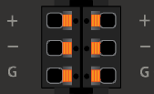
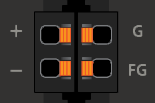
Selection and Setting of Communication Protocols
Setting Steps:
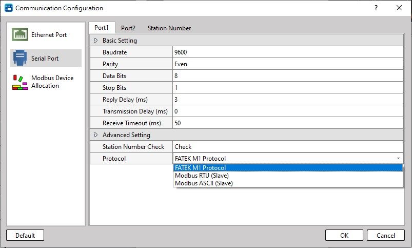
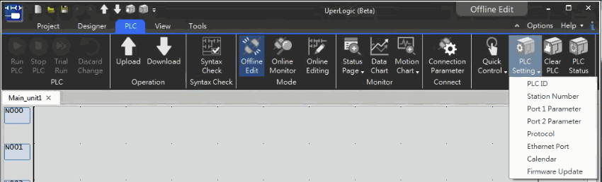
- Select Communication Configuration:
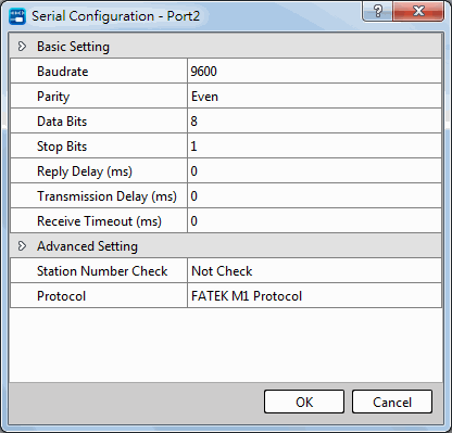
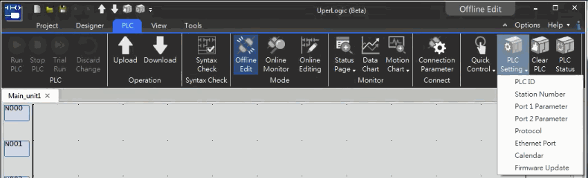
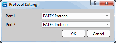
Click "Communication Configuration " of "System Configuration" in "Project Management" on the left side of the software interface, as shown in the figure below, and then click "Serial Port Settings".
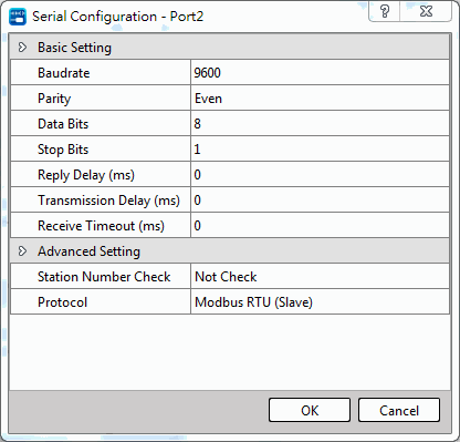
At this time, you can select the Modbus or FATEK communication protocol in the "Communication Configuration " in the "Advanced Settings" below, as shown in the figure below.
After the setting is completed, download it to the PLC.
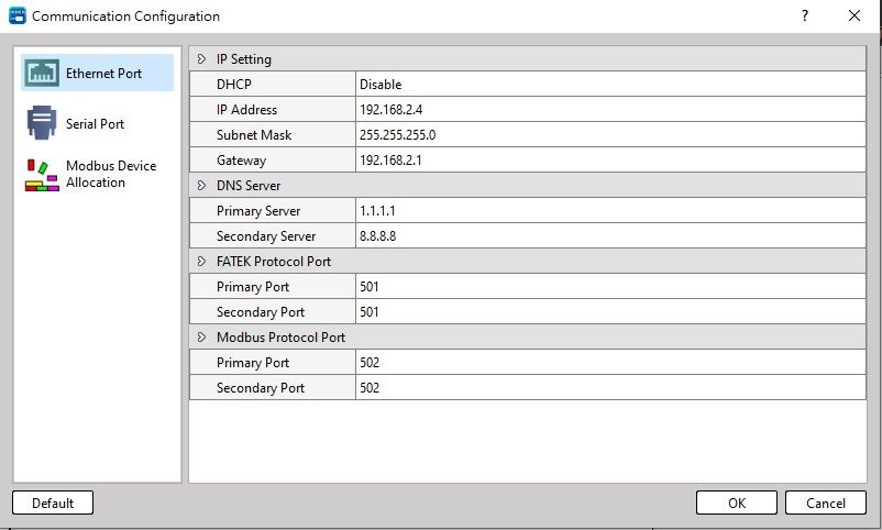
- Set protocol via special register:
R35355:High byte = 56H, the planned communication port is Modbus RTU / Modbus ASCII communication protocol interface.
= other values, don’t have the function above.
(FATAK communication protocol as default)
Low byte = Port1~4, FATEK / Modbus RTU / Modbus ASCII, the specified format of the communication protocol is as follows:
High byte Low byte
|
56H |
b7 |
b6 |
b5 |
b4 |
b3 |
b2 |
b1 |
b0 |
|
Bits |
Value |
Description |
|
b1b0 |
0 or 1 |
Port1/Port3 works FATEK communication protocol |
|
2(b1:1, b0:0) |
Port1/Port3 works Modbus RTU communication protocol |
|
|
3(b1:1, b0:1) |
Port1/Port3 works Modbus ASCII communication protocol |
|
|
b3b2 |
0 or 1 |
Port2/Port4 works FATEK communication protocol |
|
2(b3:1, b2:0) |
Port2/Port4 works Modbus RTU communication protocol |
|
|
3(b3:1, b2:1) |
Port2/Port4 works Modbus ASCII communication protocol |
※ It is allowed to designate multiple ports as the Modbus RTU communication protocol interface, as long as the corresponding bit is set to 1.
Setting example:
R35355=5602H, specify Port1 as Modbus RTU communication protocol interface
R35355=5608H, specify Port2 as Modbus RTU communication protocol interface
R35801=5602H, specify Port3 as Modbus RTU communication protocol interface
R35801=5608H, specify Port4 as Modbus RTU communication protocol interface
R35355=560AH, designate Port1 and Port2 as Modbus RTU communication protocol interface
R35801=560AH, designate Port3 and Port4 as Modbus RTU communication protocol interface
※ If the communication port of the PLC is to be used as a Modbus RTU / Modbus ASCII slave station, it can be used by planning a Modbus RTU / Modbus ASCII communication protocol interface according to the above method, and the Modbus address configuration must meet the application requirements.
※ Please refer to Chapter 10-4-2 for the conversion principles of Modbus and FATEK data addresses.
Port 1~Port 4 work as the master station of Modbus RTU/ASCII communication protocol
※ If PLC communication port is a Master station of Modbus RTU/Modbus ASCII, please follow FUN150 (M-BUS) instruction (refer to below diagram). Please refer to Chapter 10-4 for further details of FUN150 (M-BUS) instruction.

Settings for Communication Parameters
The factory default or system initial values of the communication parameters of Port 1~Port 4 are as follows:
|
Baud Rate |
9600 bps |
|
Data length |
8 Bits |
|
Parity Check |
Even |
|
Stop Bit |
1 Bit |
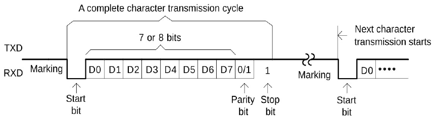
Default communication parameters
|
Port |
Register Setup |
Default Value |
Default Baud Rate |
Other Default Parameters |
|
Port 1 |
R35352 |
5661H |
9600 bps |
8-bit Data、 Even、1-bit Stop |
|
Port 2 |
R35353 |
5661H |
9600 bps |
8-bit Data、 Even、1-bit Stop |
|
Port 3 |
R35798 |
5661H |
9600 bps |
8-bit Data、 Even、1-bit Stop |
|
Port 4 |
R35799 |
5661H |
9600 bps |
8-bit Data、 Even、1-bit Stop |
※ When a port is set to Modbus RTU communication protocol, data bit is always 8-bit.
※ Port 1~Port 4 also provide Baud Rate settings for user-defined (4800 bps~1152000 bps).
Setup of Port 1~Port 4 communication parameters
Port communication parameters can be found by Project->Communication Configuration->Serial Port.
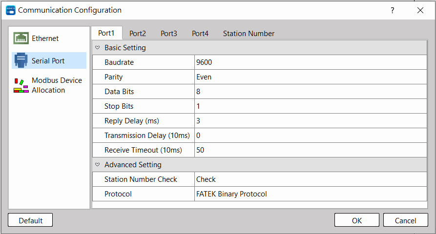
Without station number checking for HMI or SCADA connecting
While PLC communicating with UperLogic, it recognizes the FATEK M1 communication protocol.
While PLC communicating with Man Machine Interface (MMI) or Supervising software (SCADA), it recognizes the FATEK binary communication protocol.
Low byte of R35354 = 1, Port 1 without station number checking while FATEK’s external communication protocol.
High byte of R35354 = 1, Port 2 without station number checking while FATEK’s external communication protocol.
Low byte of R35800 = 1, Port 3 without station number checking while FATEK’s external communication protocol.
High byte of R35800 = 1, Port 4 without station number checking while FATEK’s external communication protocol.
Transmission delay time setting
While the communication port being used as the master of FATEK CPU LINK (FUN151) or Modbus RTU (FUN150) network, it allows the user to set the transmission delay time to slow down the expiration of message frame.
High byte of R35357: Port 1 transmission delay time setting (Unit in 10mS)
High byte of R35358: Port 2 transmission delay time setting (Unit in 10mS)
High byte of R35803: Port 3 transmission delay time setting (Unit in 10mS)
High byte of R35804: Port 4 transmission delay time setting (Unit in 10mS)
Receive time-out span setting
When the communication port of the PLC uses FUN150 (M-BUS) or FUN151 (CLINK) as the master of the Modbus or Fatek communication network. After sending a command, it must complete the transmission of all response messages within the set time. When the time is up, if the receiving party does not respond or the response is not completed, it is determined that the communication transaction command has failed.
Low byte of R35357: Port 1 receive time-out span setting (Unit in 10mS).
Low byte of R35358: Port 2 receive time-out span setting (Unit in 10mS).
Low byte of R35803: Port 3 receive time-out span setting (Unit in 10mS).
Low byte of R35804: Port 4 receive time-out span setting (Unit in 10mS).
New message detection time interval setting
While the communication port being used as the master or slave of Modbus RTU communication protocol, the system will give the default time interval to identify each packet of receiving message.
Without station number checking for FATEK’s internal communication protocol
While PLC communicating with UperLogic, it recognizes the FATEK’s internal communication protocol, the quick way to communicate with the PLC is to key in 255 as the station number for UperLogic to connect with the unsure station number of target.
Related internal relay
|
Communication Port |
Port ready Indication relay |
Indication relay to complete the last command |
|
Port1 |
M9135 |
M9136 |
|
Port2 |
M9138 |
M9139 |
|
Port3 |
M9149 |
M9150 |
|
Port4 |
M9152 |
M9153 |
10-1-3 Description and Application of Software Interface Types
As described in Section 10.1, the built-in communication port has 3 types of software interfaces, Port1~Port2 are both Standard Interface and Ladder Function Interface. Port3~Port4 are both Plugged-in Interface and Ladder Function Interface. The interface type is based on PLC’s CPU of user’s program setting (when user used communication-controlled instruction FUN150 and FUN151, it will automatically set to “Ladder Diagram Program Controlled Interface”).
Standard/Plugged-in Interface
Standard and plugged-in interface differs in that plugged-in ones are not inherently built in, and only MQ-series PLC supports this kind of interface. The interface is controlled by PLC CPU, and the communication transaction of the ports is controlled by FATEK “Standard Communication Driver” or “Modbus Communication Driver”. All accesses to the port must be executed in the format of “FATEK-PLC Protocol” or “Modbus Communication Driver”. UperLogic software package, and many HMI and SCADA have communication drivers conforming to “FATEK-PLC Protocol”, so linkage is built immediate when the “standard interface” port is connected and the hardware interface and communication parameters are consistent. When no such conforming communication driver is available, additional commands that conform to the format of “FATEK-PLC Protocol” or “Modbus Communication Driver” must be written for PLC communication.
Ladder Function Interface
This type of interface can be set up for Port1~Port4. The ladder program that are used to control the ports are FUN150 (M-BUS) and FUN151 (CLINK).
FUN150 (M-BUS) controls Port 1~Port 4 and uses them as masters on the Modbus network. The ports can connect to Modbus peripherals (slaves) easily. Refer to the “Convenient instruction for Modbus RTU Master” below for more information.
FUN151 (CLINK) controls Port 1~Port 4and uses them for resource sharing among PLCs or connection to intelligent peripherals. FUN151 provides three operation modes. Refer to the “FATEK Binary Master/Slave Protocols” below for more information.
10-2 FATEK Binary Communication Protocol
FUN151 (CLINK) Usage Step
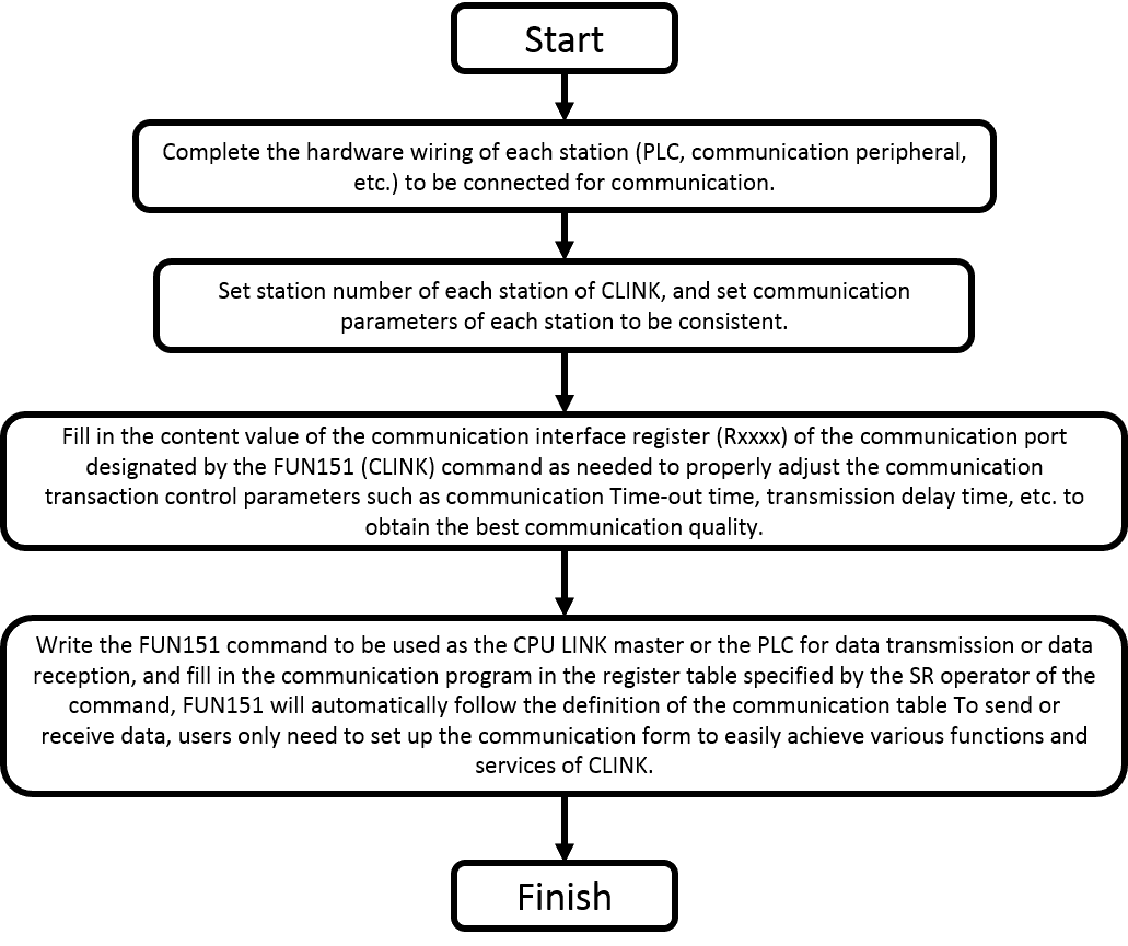
- Station number can be any one from 1 to 254, but cannot be repeated
- Please refer to the section Communication parameter setting instructions.
- MD3 is only for Port2.
10-2-1 Description and examples of instruction
This chapter will explain the usage of the MD0 working modes of the FUN151 (CLINK) command with practical application examples.
FUN151(CLINK):MD0 Communication Connection Facilitation Command
|
FUN151 CLINK |
FUN151(CLINK):MD0 Communication Connection Facilitation Command (which makes PLC act as the master station in FATEK communication protocol through PORT 1~4) |
FUN151 CLINK |
||||||||||||||||||||||||||||||
|
Symbol |
||||||||||||||||||||||||||||||||
|
|
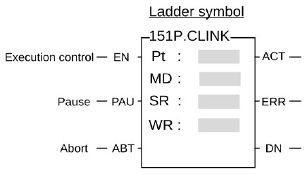
Pt : Assign the port, 1~4 MD: 0, master station of CPU LINK (Using FATEK communication protocol). SR: Starting register of communication table WR: Starting register for instruction operation. It controls 8 registers; the other programs can not repeat in using. |
|||||||||||||||||||||||||||||||
|
||||||||||||||||||||||||||||||||
|
FUN151 CLINK |
FUN151(CLINK):MD0 Communication Connection Facilitation Command (which makes PLC act as the master station in FATEK communication protocol through PORT 1~4) |
FUN151 CLINK |
|
Description |
||
|
||
|
FUN151 CLINK |
FUN151(CLINK):MD0 Communication Connection Facilitation Command (which makes PLC act as the master station in FATEK communication protocol through PORT 1~4) |
FUN151 CLINK |
|||||||||||||||||||||||||
|
Description |
|||||||||||||||||||||||||||
|
Port Interface Signal List of relays and registers used by communication ports:
|
|||||||||||||||||||||||||||
|
FUN151 CLINK |
FUN151(CLINK):MD0 Communication Connection Facilitation Command (which makes PLC act as the master station in FATEK communication protocol through PORT 1~4) |
FUN151 CLINK |
|
Example |
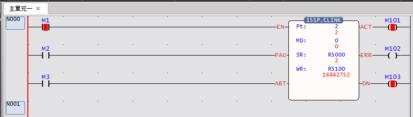
Use Port 2 to execute communication command program |
|
|
When M1 = ON, the master station will continue to read the slave station data through Port 2, or write data to the slave station |
||
|
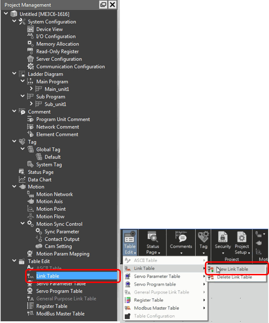
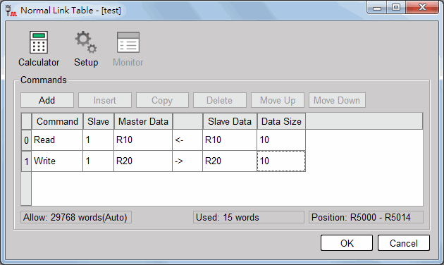
Editing Communication Table with UperLogic Click the “Link Table” Item which in project windows: Project name Table Edit Link Table 🡪 Click right button and select “New Link Table”. |
||
|
FUN151 CLINK |
FUN151(CLINK):MD0 Communication Connection Facilitation Command (which makes PLC act as the master station in FATEK communication protocol through PORT 1~4) |
FUN151 CLINK |
|
Figure 57 Table of communication command |
||
|
FUN151 CLINK |
FUN151(CLINK):MD0 Communication Connection Facilitation Command (which makes PLC act as the master station in FATEK communication protocol through PORT 1~4) |
FUN151 CLINK |
|
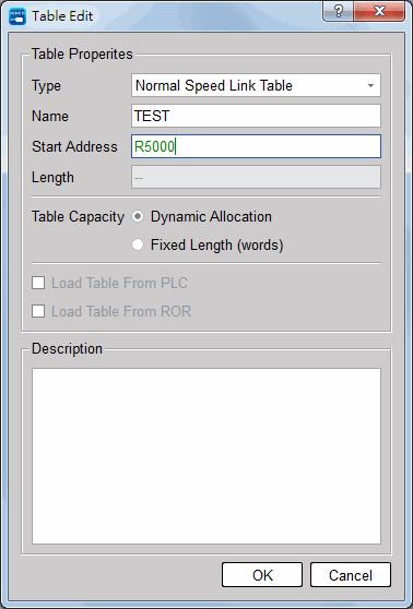
Figure 58 Table of Normal Link
※ To make it easy to edit, read, and maintain the communication program, we have extended following related instructions under FUN150 and FUN151. The use method is taking focus on FUN150 or FUN151, and press the hotkey “Z”. When “Table Edit” windows appear, then you can edit the communication table. |
||
|
FUN151 CLINK |
FUN151(CLINK):MD0 Communication Connection Facilitation Command (which makes PLC act as the master station in FATEK communication protocol through PORT 1~4) |
FUN151 CLINK |
|
Figure 59 Table of Normal Link_Communicatoin Command Setting
|
||
|
FUN151 CLINK |
FUN151(CLINK):MD0 Communication Connection Facilitation Command (which makes PLC act as the master station in FATEK communication protocol through PORT 1~4) |
FUN151 CLINK |
||||||||||||||||||||||||
|
Explanation for MD0 Operand SR SR:Starting register for communication program of CLINK instruction。
|
||||||||||||||||||||||||||
|
FUN151 CLINK |
FUN151(CLINK):MD0 Communication Connection Facilitation Command (which makes PLC act as the master station in FATEK communication protocol through PORT 1~4) |
FUN151 CLINK |
||||||||||||||||||||||||
|
||||||||||||||||||||||||||
|
FUN151 CLINK |
FUN151(CLINK):MD0 Communication Connection Facilitation Command (which makes PLC act as the master station in FATEK communication protocol through PORT 1~4) |
FUN151 CLINK |
|||||||||||||||||||||||||||||||||||||||||||||
|
Master/Slave data type, code and reference number
Note: The data type for master and slave must be consistent. i.e., if the master station is any value between 0 to 5, the slave station must also be any value between 0 to 5; if the master station is any value between 6 to 13, the slave station must also be any value between 6 to 13. |
|||||||||||||||||||||||||||||||||||||||||||||||
|
FUN151 CLINK |
FUN151(CLINK):MD0 Communication Connection Facilitation Command (which makes PLC act as the master station in FATEK communication protocol through PORT 1~4) |
FUN151 CLINK |
||||||||||||||||||||||||||||||
|
FUN151: Explanation for the Operand WR of MD0 High Byte Low Byte
Result code: 0, this transaction is successful. 2, data length error (data length is 0 or greater than 64 in one transaction). 3, command code error (command code is greater than 2). 4, data type error (data type is greater than 13, please refer to data type code). 5, reference number error (please refer to reference number). 6, inconsistence in data type (e.g., master station is 0~5 while slave is 6~13). A, no response from slave station (Time-out error). B, communication error (received error data). |
||||||||||||||||||||||||||||||||
|
FUN151 CLINK |
FUN151(CLINK):MD0 Communication Connection Facilitation Command (which makes PLC act as the master station in FATEK communication protocol through PORT 1~4) |
FUN151 CLINK |
||||||||||||||||||||||||||||||
Communication Table for Normal Link (MD0)
|
||||||||||||||||||||||||||||||||
10-3 User-Defined Communication Protocols
The functions of MD1 and MD4 are both connected to intelligent peripheral devices with a counterpart communication interface, so that PLC can be used as data transmission (automatic transmission) through Port 1 and 4. The difference is that the transmission data of MD1 will only occupy one Low Byte in a Word, while the transmission data of MD4 will occupy the High Byte and Low Byte in a Word.
The functions of MD2 and MD5 are ready to receive at any time. The message sent by the intelligent peripheral equipment of the RS485 communication interface makes the PLC receive data through these ports (passive reception). The difference is that the received data of MD2 will only occupy one Low Byte in a Word, and the received data of MD5 will occupy the High Byte and Low Byte in a Word.
10-3-1 Instruction description and examples
This chapter will explain the usage of the working modes (MD1, MD4, MD2, MD5) of FUN151 (CLINK) command with examples of actual applications.
FUN151(CLINK):MD1、MD4 Communication Connection Convenience Command
|
FUN151 CLINK |
FUN151(CLINK):MD1、MD4 Communication Connection Convenience Command ( Use PLC as a data transmission unit via Port 1~Port 4 ) |
FUN151 CLINK |
||||||||||||||||||||||||||||||
|
Symbol |
||||||||||||||||||||||||||||||||
|
|
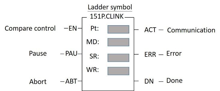
Pt:Assign communication port, 1~4. MD:1 & 4;Connect with intelligent peripheral devices with serial communication interfaces. SR:Communication transmission table start register. (Look at the example description). WR:Instruction operation start register (see example description), a total of 8 registers are occupied, and other programs cannot be reused. |
|||||||||||||||||||||||||||||||
MD1 and MD4 are used to connect with intelligent peripheral devices with RS-485 communication interface, so that PLC can be used as data transmission (automatic transmission) through Port 1~Port 4. The difference is that the transmission data of MD1 will only occupy one Low Byte in a Word, and the transmission data of MD4 will occupy the High Byte and Low Byte in a Word, please refer to the description of the follow-up SR for details. |
||||||||||||||||||||||||||||||||
|
FUN151 CLINK |
FUN151(CLINK):MD1、MD4 Communication Connection Convenience Command ( Use PLC as a data transmission unit via Port 1~Port 4 ) |
FUN151 CLINK |
|
Function Description |
||
|
||
|
FUN151 CLINK |
FUN151(CLINK):MD1、MD4 Communication Connection Convenience Command ( Use PLC as a data transmission unit via Port 1~Port 4 ) |
FUN151 CLINK |
|||||||||||||||||||||||||
|
Function Description |
|||||||||||||||||||||||||||
|
Port Interface Signal List of relays and registers used by communication ports:
High Byte: For MD1, it is recommended to set it to 0. |
|||||||||||||||||||||||||||
|
FUN151 CLINK |
FUN151(CLINK):MD1、MD4 Communication Connection Convenience Command ( Use PLC as a data transmission unit via Port 1~Port 4 ) |
FUN151 CLINK |
|
Example |
Using Port 2 to actively connect with smart peripherals using non-standard communication protocols |
|
|
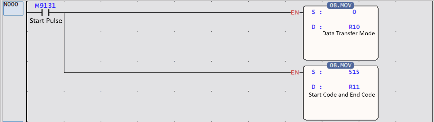
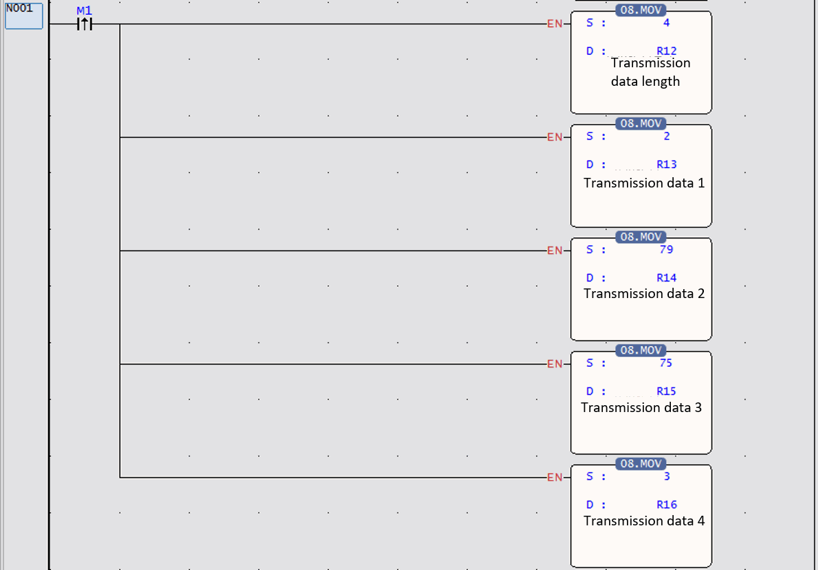
Example description: Actively and continuously send 02H (‘STX’), 4FH (‘ O’), 4BH (‘K’), 03H (‘ETX’) through PLC Port 2 to intelligent peripheral devices with RS485 communication interface. |
||
|
Example N000:
|
||
|
Program Description:
|
||
|
FUN151 CLINK |
FUN151(CLINK):MD1、MD4 Communication Connection Convenience Command ( Use PLC as a data transmission unit via Port 1~Port 4 ) |
FUN151 CLINK |
|
Program Example N001:
|
||
|
Program Description: Package transmission data:
Fill in the data to be sent:
|
||
|
FUN151 CLINK |
FUN151(CLINK):MD1、MD4 Communication Connection Convenience Command ( Use PLC as a data transmission unit via Port 1~Port 4 ) |
FUN151 CLINK |
|
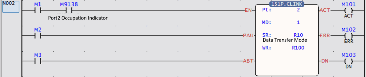
Program Example N002:
|
||
|
Program Description:
|
||
|
FUN151 CLINK |
FUN151(CLINK):MD1、MD4 Communication Connection Convenience Command ( Use PLC as a data transmission unit via Port 1~Port 4 ) |
FUN151 CLINK |
||||||||||||||||||||||
|
FUN 151: Explanation of MD1 operand SR SR: The initial register for the data transfer form.
|
||||||||||||||||||||||||
|
FUN151 CLINK |
FUN151(CLINK):MD1、MD4 Communication Connection Convenience Command ( Use PLC as a data transmission unit via Port 1~Port 4 ) |
FUN151 CLINK |
|
Note:
|
||
|
FUN151 CLINK |
FUN151(CLINK):MD1、MD4 Communication Connection Convenience Command ( Use PLC as a data transmission unit via Port 1~Port 4 ) |
FUN151 CLINK |
|||||||||||||||||||||||||||||||||||||||||||||||||||||||||||
|
FUN151: Description of MD1 operand WR High Byte Low Byte
|
|||||||||||||||||||||||||||||||||||||||||||||||||||||||||||||
|
FUN151 CLINK |
FUN151(CLINK):MD1、MD4 Communication Connection Convenience Command ( Use PLC as a data transmission unit via Port 1~Port 4 ) |
FUN151 CLINK |
|
Result Code: 0, The transfer (transaction) was successful. 2, Data length error(The value is 0, or a transaction volume is greater than 1024). |
||
FUN151(CLINK):MD2、MD5 Communication Connection Convenience Command
|
FUN151 CLINK |
FUN151(CLINK):MD2、MD5 Communication Connection Convenience Command ( Use PLC as a data transmission unit via Port 1~Port 4 ) |
FUN151 CLINK |
||||||||||||||||||||||||||||||
|
Symbol |
||||||||||||||||||||||||||||||||
|
|
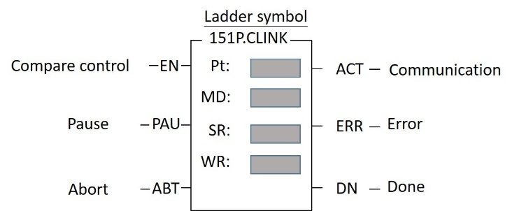
Pt:Assign port, 1~4. MD:2, 5; always be ready to receive messages from intelligent peripheral devices with serial communication interfaces. SR:The initial register of the communication transmission table (refer to example description). WR:Instruction operation start register (refer to example description), a total of 8 registers are occupied, and other programs cannot be reused. |
|||||||||||||||||||||||||||||||
The functions of MD2 and MD5 are ready to receive at any time. The message sent by the intelligent peripheral equipment of the serial communication interface makes the PLC receive data through Port 1~Port 4 (passive reception). The difference is that the received data of MD2 will only occupy the Low Byte part of a Word, and the received data of MD5 will occupy the High Byte and Low Byte of a Word, please refer to the description of the follow-up SR for details. |
||||||||||||||||||||||||||||||||
|
FUN151 CLINK |
FUN151(CLINK):MD2、MD5 Communication Connection Convenience Command ( Use PLC as a data transmission unit via Port 1~Port 4 ) |
FUN151 CLINK |
|||||||||||||||||||||||||
|
Description |
|||||||||||||||||||||||||||
|
|||||||||||||||||||||||||||
|
Port Interface Signal List of relays and registers used by communication ports:
|
|||||||||||||||||||||||||||
|
FUN151 CLINK |
FUN151(CLINK):MD2、MD5 Communication Connection Convenience Command ( Use PLC as a data transmission unit via Port 1~Port 4 ) |
FUN151 CLINK |
Note: 1:FUN151: MD2 and MD5 stay in the receiving state as long as they start receiving, unless the input signal of abandon receiving (ABT) is ON, they will leave the receiving state to stop receiving and wait for the next start of receiving control. 2: When the start/end code of reception is changed, it is necessary to control the ABT input signal ON, and then start the reception control "EN↑" from 0→1 to start receiving messages. |
||
|
FUN151 CLINK |
FUN151(CLINK):MD2、MD5 Communication Connection Convenience Command ( Use PLC as a data transmission unit via Port 1~Port 4 ) |
FUN151 CLINK |
|
Example |
Use Port2 to return the data received by this PLC to the CPU Unit that sent the data |
|
|
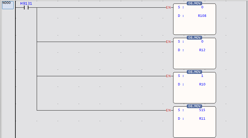
Program Example N000:
|
||
|
Program Description:
(The start code is High Byte and the end code is Low Byte) |
||
|
FUN151 CLINK |
FUN151(CLINK):MD2、MD5 Communication Connection Convenience Command ( Use PLC as a data transmission unit via Port 1~Port 4 ) |
FUN151 CLINK |
|
Example |
Use Port2 to return the data received by this PLC to the CPU Unit that sent the data |
|
|
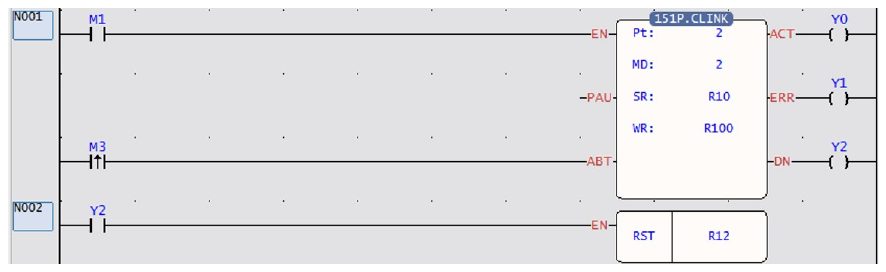
Program Example N001 ~ N002:
Program Description:
|
||
|
FUN151 CLINK |
FUN151(CLINK):MD2、MD5 Communication Connection Convenience Command ( Use PLC as a data transmission unit via Port 1~Port 4 ) |
FUN151 CLINK |
|
Example |
Use Port2 to return the data received by this PLC to the CPU Unit that sent the data |
|
|
Program Example N003 ~ N004:
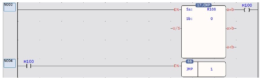
Ladder Program Description:
|
||
|
FUN151 CLINK |
FUN151(CLINK):MD2、MD5 Communication Connection Convenience Command ( Use PLC as a data transmission unit via Port 1~Port 4 ) |
FUN151 CLINK |
|
Example |
Use Port2 to return the data received by this PLC to the CPU Unit that sent the data |
|
|
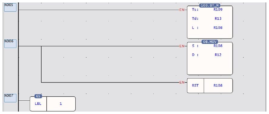
Ladder Program Example N005 ~ N007:
|
||
|
Program Description:
|
||
|
FUN151 CLINK |
FUN151(CLINK):MD2、MD5 Communication Connection Convenience Command ( Use PLC as a data transmission unit via Port 1~Port 4 ) |
FUN151 CLINK |
|||||||||||||||||||||
|
FUN151: Description of MD2 operand SR SR: The initial register of the data transmission form.
|
|||||||||||||||||||||||
|
FUN151 CLINK |
FUN151(CLINK):MD2、MD5 Communication Connection Convenience Command ( Use PLC as a data transmission unit via Port 1~Port 4 ) |
FUN151 CLINK |
|
Note:
|
||
|
FUN151 CLINK |
FUN151(CLINK):MD2、MD5 Communication Connection Convenience Command ( Use PLC as a data transmission unit via Port 1~Port 4 ) |
FUN151 CLINK |
||||||||||||||||||||||||||||||||||||||||||||||||||||||||||||||||||||||||||||||
|
FUN151: Description of MD2 operator WR High Byte Low Byte
|
||||||||||||||||||||||||||||||||||||||||||||||||||||||||||||||||||||||||||||||||
|
FUN151 CLINK |
FUN151(CLINK):MD2、MD5 Communication Connection Convenience Command ( Use PLC as a data transmission unit via Port 1~Port 4 ) |
FUN151 CLINK |
|
Note: When the CPU receives a complete message, it will fill the received data into the receiving register and set the receiving length, so before the Ladder program starts receiving, the receiving data length register (WR+8) can be cleared to Zero, as long as the received data length register is not zero, it means that a new message has been received; after the Ladder program reads the received data, it clears the received data length register to zero. As long as the received data length register is not zero, it means that a new message has been received, so that the receiving action can be easily processed. Result Code: 0, the data transaction is successful. 2, The data length is wrong (the value is 0, or the transaction volume is greater than 1024). A, Unable to respond to messages within the Time-out time (receive and transmit mode). B, Abnormal communication (wrong data received). |
||
10-4 Modbus RTU/ASCII Communication Protocols
Procedures for Usage
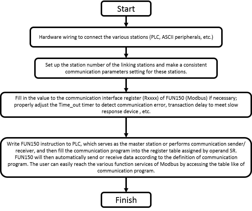
- Station number can be set to any one between 1 to 254 without replication.
- For communication parameters, please refer to the description of "Communication Related Setting".
10-4-1 Instruction description and examples
This section will instruction to explain FUN150 (Modbus) usages, with respective practical application program examples.
Convenient Instruction for Modbus RTU/ASCII Master (makes PLC as the Modbus RTU/ASCII master through Port 1~Port 4)
|
FUN150 M-BUS |
Convenient Instruction for Modbus RTU/ASCII Master (makes PLC as the Modbus RTU/ASCII master through Port 1~Port 4) |
FUN150 M-BUS |
|||||||||||||||||||||||||
|
Symbol |
|||||||||||||||||||||||||||
|
|
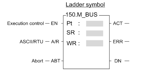
Pt:1~4, specify the communication port to work as the Modbus RTU master SR:Starting register of communication program WR:Starting register for instruction operation. It controls 8 registers; the other programs can not repeat in using. |
||||||||||||||||||||||||||
|
|||||||||||||||||||||||||||
|
FUN150 M-BUS |
Convenient Instruction for Modbus RTU/ASCII Master (makes PLC as the Modbus RTU/ASCII master through Port 1~Port 4) |
FUN150 M-BUS |
|
Description |
||
|
||
|
FUN150 M-BUS |
Convenient Instruction for Modbus RTU/ASCII Master (makes PLC as the Modbus RTU/ASCII master through Port 1~Port 4) |
FUN150 M-BUS |
|||||||||||||||||||||||||
Interface Signals Dedicated Relays and Registers for corresponding port:
ON, it represents that port is free and ready. OFF, it represents that port is busy, data transaction is going.
|
|||||||||||||||||||||||||||
|
FUN150 M-BUS |
Convenient Instruction for Modbus RTU/ASCII Master (makes PLC as the Modbus RTU/ASCII master through Port 1~Port 4) |
FUN150 M-BUS |
The content of Low Byte defines the receive time-out span of M-BUS instruction. The M-BUS instruction employs receive time-out span to judge whether the slave station on line or not. When the master PLC sent out the read/write command to the slave station, the slave station didn’t reply within this period means that there is abnormal event in communication called Time-out. When there are multi-drop linking, properly adjust this value (greater than 1 scan time of the slave station with the longest scan time) to shorten the communication response time among the active linking stations if there are many slave stations power off (The time-out cases will happen).
|
||
|
FUN150 M-BUS |
Convenient Instruction for Modbus RTU/ASCII Master (makes PLC as the Modbus RTU/ASCII master through Port 1~Port 4) |
FUN150 M-BUS |
|
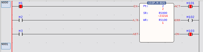
Example |
Communicate with Modbus devices via Port 2 |
|
|
Description
|
||
|
FUN150 M-BUS |
Convenient Instruction for Modbus RTU/ASCII Master (makes PLC as the Modbus RTU/ASCII master through Port 1~Port 4) |
FUN150 M-BUS |
|
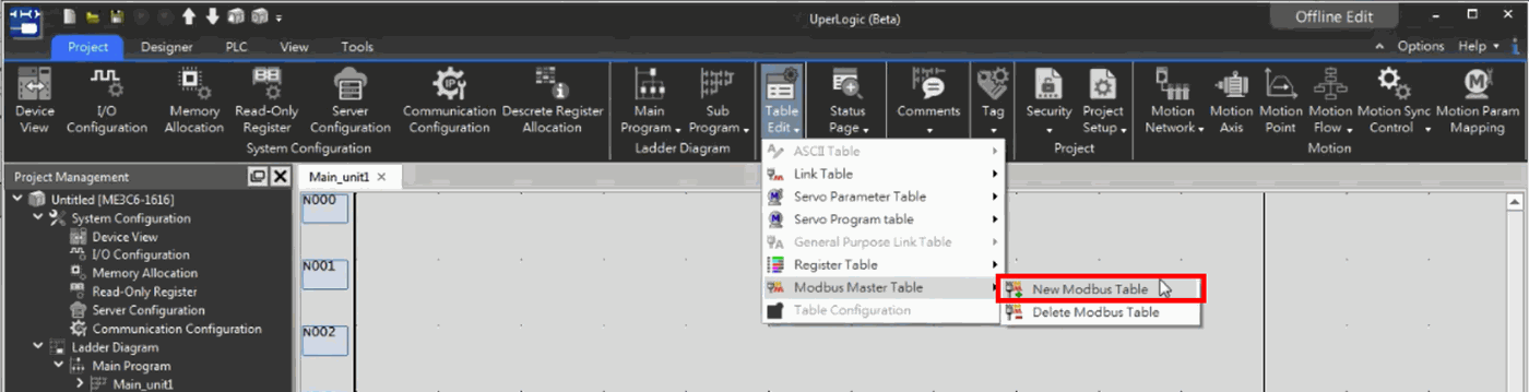
Editing Communication Table with UperLogic Click the “Modbus Master” Item which in project windows: Modbus Master Table: Project name Table Edit Modbus Master 🡪Click right button and select “Add Modbus Master Table”
Figure 60 Adding Modbus Master Table |
||
|
FUN150 M-BUS |
Convenient Instruction for Modbus RTU/ASCII Master (makes PLC as the Modbus RTU/ASCII master through Port 1~Port 4) |
FUN150 M-BUS |
|
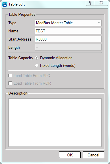
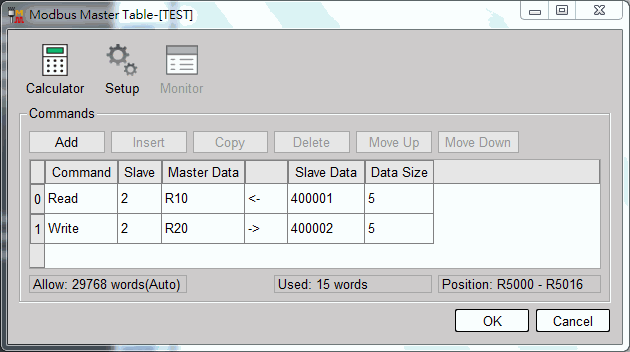
Figure 61 Editing Modbus Master Table
|
||
|
FUN150 M-BUS |
Convenient Instruction for Modbus RTU/ASCII Master (makes PLC as the Modbus RTU/ASCII master through Port 1~Port 4) |
FUN150 M-BUS |
|
|
||
|
FUN150 M-BUS |
Convenient Instruction for Modbus RTU/ASCII Master (makes PLC as the Modbus RTU/ASCII master through Port 1~Port 4) |
FUN150 M-BUS |
||||||||||||||||||||||||||||||||||
|
Description of FUN150 operand SR SR:Starting register for communication program of M-BUS instruction.
|
||||||||||||||||||||||||||||||||||||
|
FUN150 M-BUS |
Convenient Instruction for Modbus RTU/ASCII Master (makes PLC as the Modbus RTU/ASCII master through Port 1~Port 4) |
FUN150 M-BUS |
|||||||||||||||||||||||||||
|
Description of FUN150 operand SR
|
|||||||||||||||||||||||||||||
|
FUN150 M-BUS |
Convenient Instruction for Modbus RTU/ASCII Master (makes PLC as the Modbus RTU/ASCII master through Port 1~Port 4) |
FUN150 M-BUS |
|||||||||||||||||||||||||||||||||
Note: The master and slave data types must be the same, if the master station is Y/M/S, the slave station must be 0/1; If the master station is R/D, the slave station must be 3/4; and vice versa. |
|||||||||||||||||||||||||||||||||||
|
FUN150 M-BUS |
Convenient Instruction for Modbus RTU/ASCII Master (makes PLC as the Modbus RTU/ASCII master through Port 1~Port 4) |
FUN150 M-BUS |
|||||||||||||||||||||||||||
|
Description of FUN150 operand WR High Byte Low Byte
Result code: 0, Transaction is successful. 2, Data length error (for length is 0 or over limit). 3, Command code error (Command code is 0 or greater than 3). 4, Data type error. 5, Reference number error. 6, Inconsistence in data type (e.g., master station is Y/M/S while slave is 4). 7, Port error (Not Port 1~4). 8, Invalid communication table. A, No response from slave station (Time-out error). B, Communication error (received error data or exception reply). |
|||||||||||||||||||||||||||||
|
FUN150 M-BUS |
Convenient Instruction for Modbus RTU/ASCII Master (makes PLC as the Modbus RTU/ASCII master through Port 1~Port 4) |
FUN150 M-BUS |
||||||||||
|
For easier programming and troubleshooting, the UperLogic provides the table editing environment to edit the communication table of FUN150 instruction; Key in the complete FUN150 instruction first and then move the cursor to the position of it, depressing the "Z" key, now comes the table editing environment. The user can create the new communication table or display the existed table under this friendly user interface operation. M-BUS Communication Table
|
||||||||||||
|
FUN150 M-BUS |
Convenient Instruction for Modbus RTU/ASCII Master (makes PLC as the Modbus RTU/ASCII master through Port 1~Port 4) |
FUN150 M-BUS |
|
※UperLogic provides the user friendly table edit for M-BUS Master: Command Slave Data of Master Data of Slave Data length Read 1~247 Y0~Y1023 ← 000001~065535 1~255 M0~M9119 ← 000001~065535 1~255 S0~S3103 ← 000001~065535 1~255 Y0~Y1023 ← 100001~165535 1~255 M0~M9119 ← 100001~165535 1~255 S0~S3103 ← 100001~165535 1~255 R0~R34767 ← 400001~465535 1~125 D0~D7999 ← 400001~465535 1~125 R0~R34767 ← 300001~365535 1~125 D0~D7999 ← 300001~365535 1~125 Write 0~247 Y0~Y1023 → 000001~065535 1~255 M0~M9119 → 000001~065535 1~255 S0~S3103 → 000001~065535 1~255 R0~R34767 → 400001~465535 1~125 D0~D7999 → 400001~465535 1~125 |
||
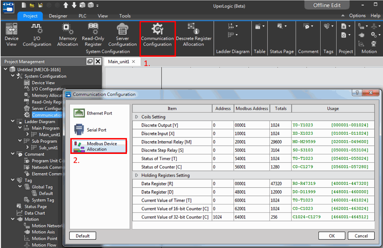
10-4-2 Address mapping between Modbus and FATEK
|
Modbus Slave |
Address mapping between Modbus and FATEK (PLC works as the slave station of Modbus Communication Protocols through Port 1~Port 4, and HCM ports) |
Modbus Slave |
|
||
|
Modbus Slave |
Address mapping between Modbus and FATEK (PLC works as the slave station of Modbus Communication Protocols through Port 1~Port 4, and HCM ports ) |
Modbus Slave |
|
||
|
Modbus Slave |
Address mapping between Modbus and FATEK (PLC works as the slave station of Modbus Communication Protocols through Port 1~Port 4, and HCM ports ) |
Modbus Slave |
|||||||||||||
See below for Modbus and FATEK data address mapping rules: Mapping Rule
|
|||||||||||||||
|
Modbus Slave |
Address mapping between Modbus and FATEK (PLC works as the slave station of Modbus Communication Protocols through Port 1~Port 4, and HCM ports ) |
Modbus Slave |
|
||
|
Modbus Slave |
Address mapping between Modbus and FATEK (PLC works as the slave station of Modbus Communication Protocols through Port 1~Port 4, and HCM ports ) |
Modbus Slave |
||||||||||||||||||||||
|
||||||||||||||||||||||||
|
Modbus Slave |
Modbus Communication Protocols |
Modbus Slave |
|||||||||||||||||||||||||||||||||
|
|||||||||||||||||||||||||||||||||||
|
Modbus Slave |
Modbus Communication Protocols |
Modbus Slave |
|||||||||||||||||||||||||||||||||
|
|||||||||||||||||||||||||||||||||||
|
Modbus Slave |
Modbus Communication Protocols |
Modbus Slave |
|
Modbus Slave |
Modbus Communication Protocols |
Modbus Slave |
|||||||||||||||||||||||||||||||||||||||||||||||||||||||
|
|||||||||||||||||||||||||||||||||||||||||||||||||||||||||
|
Modbus Slave |
Modbus Communication Protocols |
Modbus Slave |
||||||
For example, after the settings of R35402 ~ R35434 are completed, M9162 is turned ON for a pulse, which means that the corresponding access mode is adjusted through the PLC register method.
|
||||||||
M-Series PLC is designed with an Ethernet communication port. Such port provides a number of Ethernet functions for the user to combine with network-related equipment or applications, such as combining with IoT application.
Functional specifications
Meet the IEEE802.3 standard and provide 10/100 Base T interface.
Basic purpose
Provide the UperLogic for using FATEK on PC in order to realize communication with the Ethernet communication port of M-Series PLC through the Ethernet, including the project online uploading and downloading as well as PLC data online monitoring, etc.
It can also be connected with the Ethernet interface mounted FATEK communication drive program device or with the Modbus drive program related UperLogic, HMI and graphical control devices, etc.
Derivative purpose
In addition to the aforesaid functions, this product also provides the following functions and they will be described in the subsequent paragraphs.
- NTP (Network Time Protocol) time synchronization. Through the appointed NTP server address, it allows the designed to run the time synchronization through the network.
- MQTT publishing/subscription functions, allowing more efficient remote monitoring and data swapping through the IoT.
- Modbus TCP master/slave communication protocol function. Through the Ethernet, the user may communicate with the device provided for supporting the Modbus protocol.
10-5 FATEK Binary communication Protocol
FATEK Binary Communication Protocol is an open protocol, with which any device is able to connect to M PLC accordingly. Both serial and Ethernet communication support this protocol.
Please refer to the Fatek Binary communication manual for details.
Tip: press ← → to switch chapters, Ctrl+K to search