|
⚠Danger |
|
This section describes how to set up the reports, link parameters and command tables. Through the user-friendly interface, it minimizes the complicated procedure when operated by the user. Provided below is the operation method of the respective table.
7-1 Table Management
7-1-1 Adding New Table
To add a table, please select [Table Edit] → [OOOO Table] → [New OOOO Table] in the project window, or select [Project] → [Table Edit] → [New OOOO Table], as shown below:
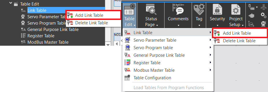
Fig. 134: Adiing a new table
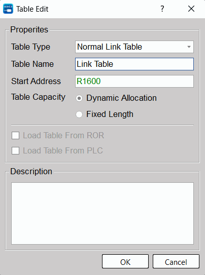
After clicking [New OOOO Table], the table editing window will pop up allowing users to create table properties.
|
Item |
Description |
|
Type |
The subcategory of the table, which varies from data table to data table. |
|
Name |
The name of the table |
|
Start Address |
The starting address to use for this table, which can be entered as a register or a label. |
|
Length |
The length used by the table data; the unit is a word group. |
|
Table Capacity |
Choose whether you want to dynamically adjust the table capacity or a fixed capacity limit:
|
|
Load Table From PLC |
To load corresponding link tables from PLC. |
|
Load Table From ROR |
To load corresponding link tables from ROR. |
|
Description |
Provides users the description of editing tables |
7-1-2 Table Edit
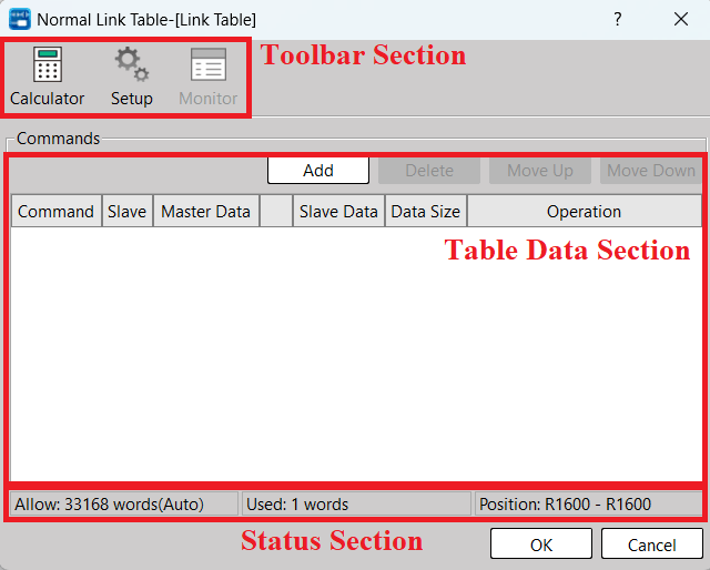
After adding a table, you will enter the table data window. In addition, you can enter the table editing window from [Table Edit] → [OOOO Table] → [Name] in the project window, or click [Project] → [Table Edit] → [OOOO Table] → [Name].
Users can edit the command details for this form in this window.
|
Function |
Description |
||
|
Toolbar Section |
Calculator |
Calling the easy-to-use calculator installed in the Windows. |
|
|
Setting |
Calling the table edit window. It allows the user to rename the table or change the home address of such table. |
||
|
Monitor |
The execution status of form commands can be monitored. The monitoring content depends on different form types, and the content will be described in detail in subsequent chapters. This function is only supported online and can be used by calling the Zooming function on the ladder diagram. |
||
|
Table Data Section |
Table data editing section, the content depends on different form types, and will be described in detail in subsequent chapters. |
||
|
Status Section |
Allow |
The display table property is set to dynamic allocation or fixed length, and the maximum length is marked; the unit is a word group. |
|
|
Used |
Displays the length of the table command currently used, and the unit is a word group. |
||
|
Position |
Displays the address range currently used by table commands. |
||
7-1-3 Rename
To change the name of the table, please select the table [Name] to be modified in [Table Edit] → [OOOO Table] in the project window, select [Rename] from the right-click menu or use the shortcut key “F2” to edit the name. In addition, you can directly enter the form editing window and change the name through editing properties.
7-1-4 Delete Table
To delete a table, please select [Table Edit] → [OOOO Table] in the project window, and select [Delete OOOO Table] from the right-click menu, or [Project] → [Table Edit] → [Delete OOOO Table] in the execution function bar, as shown in the figure below:
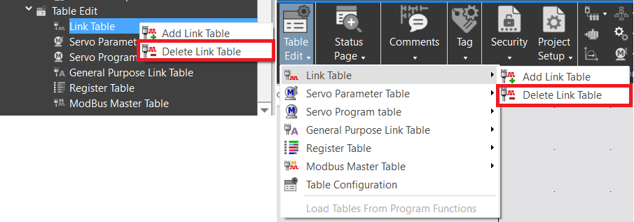
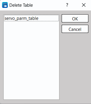
After the delete table window appears, select the table you want to delete and confirm. You can delete multiple selections.
7-1-5 Table Configuration Adjustment
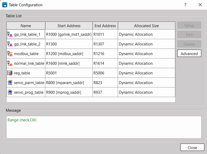
Uperlogic provides a table overview function, which can be used to determine whether the addresses used in the tables overlap to avoid misuse during program execution. To use this function, please select [Table Configuration Adjustment] from the right-click menu in [Table Edit] in the project window, or [Project] → [Table Edit] → [Table Setting Adjustment] in the execution function bar.
|
Item |
Description |
|
Table |
Display the basic properties of all tables of the current project. If the start address is marked with [OOO], it means that the address uses a label as the start address. |
|
Configuration |
Enter the table editing window to modify the properties of the table. |
|
Edit |
Enter the table data window to modify the table data. |
|
Delete |
Delete the selected table. |
|
Write to PLC |
Write the current project table data to PLC. |
|
Table Comparison |
Compare the data in the current project table with the data in the PLC register. |
|
Message |
Shows whether the addresses currently used between tables have overlapping ranges. |
7-2 Link Table
The main purpose of the link table is to facilitate users to fill in the data content of the communication command FUN151 CLINK. The [General Online Table] category corresponds to MD0. For other descriptions of corresponding commands, please refer to the advanced manual.
7-2-1 Table Value
The table data section of [General Online Table] is as shown in the figure below. Users can edit individual commands of [General Online Table] through simple operations, and the content corresponds to the command Start Register (SR) on FUN151.
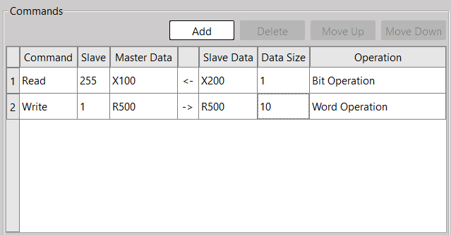
The operation description is shown as below:
|
Item |
Description |
||
|
Operation |
New |
After clicking, a row of commands will be added in the editing section for users to edit. |
|
|
Delete |
After clicking, delete the command currently selected by the user, and multiple selections can be deleted. |
||
|
Move Up |
After clicking, move the command currently selected by the user up one column. |
||
|
Move Down |
After clicking, move the command currently selected by the user down one column. |
||
|
Right-Click Menu |
Cut |
After clicking, cut the command currently selected by the user, and multiple selections can be cut. |
|
|
Copy |
After clicking, copy the command currently selected by the user, multiple selections can be copied。 |
||
|
Paste |
After clicking, paste the command previously copied or cut by the user. |
||
|
Insert |
After clicking, insert a row of commands at the selected position in the editor for users to edit. |
||
|
Delete |
After clicking, delete the command currently selected by the user, and multiple selections can be deleted. |
||
|
Move Up |
After clicking, move the command currently selected by the user up one column. |
||
|
Move Down |
After clicking, move the command currently selected by the user down one column. |
||
The command data content is shown as below:
|
Item |
Description |
|
|
Data |
No. |
Display the command information of the Nth. |
|
Command |
Edit this command action as [Read] or [Write] |
|
|
Slave |
Edit the station number of the slave station to communicate. |
|
|
Master Data |
Edit the data starting address of the Master station. |
|
|
Slave Data |
Edit the data starting address of the Slave station. |
|
|
Data Size |
The data size of such command |
|
|
Operation |
Display this command as [Bit Operation] or [Word Group Operation] |
|
7-2-2 Table Monitoring
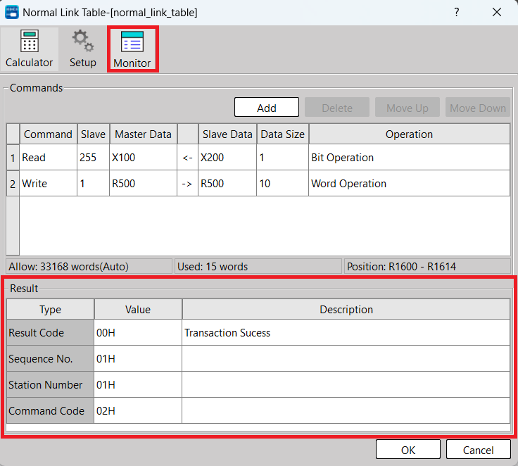
The monitoring of [General Online Table] is as shown in the figure below. Users need to be online and call the Zooming function on FUN151 to use it. The content corresponds to the command operation start register (WR) on FUN151.
|
Item |
Description |
|
Result Code |
Shows the operating result. 00H: Normal Other values: Error |
|
Operation No. |
Indicates that the Nth transaction is in operation. |
|
Station No. |
Indicates the station number of the slave station currently in communication. |
|
Command Code |
40H: Read slave PLC system status. 44H: Read the status of multiple consecutive single points of the slave PLC. 45H: Write the state of multiple consecutive single points of the slave PLC. 46H: Read the status of multiple consecutive registers of the slave PLC. 47H: Write the status of multiple registers in the slave PLC. |
7-3 Servo Parameter Table
The main purpose of the servo parameter table is to facilitate the user to fill in the data content of the positioning program parameter setting command FUN141 MPARA. For the description of the corresponding command, please refer to the advanced manual.
7-3-1 Table Value
The table data section of [Servo Parameter Table] is as shown in the figure below, users can edit individual parameters of [Servo Parameter Table] through simple operations, and the content corresponds to the command start register (SR) on FUN141.
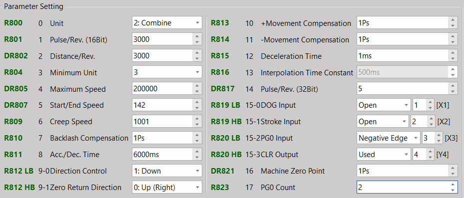
Fig. 135: Editing Servo Parameter Table
|
Parameter |
Item |
Description |
||||||||||||||||||||||||||||||
|
0 |
Unit Setting |
The unit used for the travel and speed settings used in the program. When the setting value is 0, the unit is mm, Deg, Inch, which is called the mechanical unit. When the setting value is 1, the unit is Pulse, which is called the motor unit. When the setting value is 2, the setting value is in mm, Deg, Inch, and the speed setting is in Pulse, which is called compound unit. |
||||||||||||||||||||||||||||||
|
1 |
Ps/Rev |
The number of pulses (A) required for one revolution of the motor. The range is 1~65535 Ps/Rev (when it is above 32767, set it with decimal positive number) When parameter 14 = 0, take parameter 1 as Ps/Rev. When parameter 14 ≠ 0, take parameter 14 as Ps/Rev. |
||||||||||||||||||||||||||||||
|
2 |
μM/Rev |
The distance (B) driven by the motor for one revolution. The range is 1~999999 μM/Rev (mDeg/Rev, 0.1 mInch/Rev). |
||||||||||||||||||||||||||||||
|
3 |
Min. Setting Unit |
|
||||||||||||||||||||||||||||||
|
4 |
Max. Speed Setting |
Motor and compound unit: 1-921600 Ps/Sec Mechanical unit: 1-153000 (cm/Min, x10 Deg/Min, Inch/Min), but the maximum frequency can not be greater than 921600 Ps/Sec. |
||||||||||||||||||||||||||||||
|
5 |
Start/Stop Speed |
Motor and compound unit: 1-921600 Ps/Sec。 Mechanical unit: 1-15300 (cm/Min, ×10 Deg/Min, Inch/Min), but the maximum frequency can not be greater than 921600 Ps/Sec。 |
||||||||||||||||||||||||||||||
|
6 |
Return-to-origin Deceleration Speed |
Motor and compound unit: 1-65535 Ps/Sec Mechanical unit: 1-15300 (Cm/Min, x10 Deg/Min, Inch/Min) |
||||||||||||||||||||||||||||||
|
7 |
Gear Backlash Correction Value |
Setting scope: 0-32767 Ps When walking in reverse, the walking distance will automatically add this value。 |
||||||||||||||||||||||||||||||
|
8 |
Acceleration and Deceleration Time Setting |
Setting scope: 0-30000 ms。 The time represents the one required to accelerate from rest to maximum speed (parameter 4), or decelerate from maximum speed to rest. When parameter 12=0, this parameter is used as the deceleration time. |
||||||||||||||||||||||||||||||
|
9-0 |
Direction of Operation |
When the setting value=0, forward pulse output, the current Ps value will increase; the reverse pulse output, and the current Ps value will decrease. When the set value=1, the forward pulse output and the current Ps value will decrease; the reverse pulse output and current Ps value will increase. |
||||||||||||||||||||||||||||||
|
9-1 |
Return-to-origin Direction |
When the set value=0, the return-to-origin direction is the current Ps value plus the upward direction (the origin is on the right). When the setting value=1, the return-to-origin direction is the current Ps value minus downward direction (the origin is on the left). |
||||||||||||||||||||||||||||||
|
10 |
Forward Revolution Movement Correction Value |
When outputting forward revolution pulse, this value will be automatically added as the moving distance; the range is −32768 – 32767 Ps. |
||||||||||||||||||||||||||||||
|
11 |
Compensation Value of Reverse Movement Value |
When switching to pulse wave output, this value will be automatically added as the moving distance; the range is −32768 – 32767 Ps. |
||||||||||||||||||||||||||||||
|
12 |
Deceleration Time Setting |
The range is 0-30000 ms. When parameter 12=0, parameter 8 is used as the deceleration time. When parameter 12≠0, parameter 12 is used as the deceleration time. |
||||||||||||||||||||||||||||||
|
13 |
Interpolation Acceleration/Deceleration Time Setting |
It is used to set the time required to accelerate from stillness (speed = 0) to the working frequency during linear interpolation motion; this time is also used for deceleration and stop control; the range is 0-30000 ms. |
||||||||||||||||||||||||||||||
|
14 |
Ps/Rev |
The range is 0 to 1999999. y as parameter 14 = 0, take parameter 1 as Ps/Rev. y as parameter 14 ≠ 0, take parameter 14 as Ps/Rev. |
||||||||||||||||||||||||||||||
|
15-0 |
Proximity DOG Input Contact Setting |
Can set [Normally Open], [Normally Closed] or [Not Used] input contact; contact number is X0-X15. |
||||||||||||||||||||||||||||||
|
15-1 |
Stroke Limit Input Contact Setting |
Can set [Normally Open], [Normally Closed] or [Not Used] input contact; contact number is X0-X125. |
||||||||||||||||||||||||||||||
|
15-2 |
Zero-Point Signal PG0 Input Contact Setting |
You can set [Upper Edge Count], [Lower Edge Count] or [Not Used] input contact; the contact number is X0-X15. |
||||||||||||||||||||||||||||||
|
15-3 |
Zero-Clear Signal CLR Output Contact Setting |
You can set [Use] or [Not Used] output contact; the contact number is Y0-Y23. |
||||||||||||||||||||||||||||||
|
16 |
Mechanic Original-Point Position Value |
The range is -999999-999999 Ps. |
||||||||||||||||||||||||||||||
|
17 |
Zero-Point Signal Numbers |
The range is 0-255 Count. |
||||||||||||||||||||||||||||||
7-3-2 Table Monitoring
No monitoring function is provided to [Servo Parameter Table].
7-4 Servo Program Table
The main purpose of [Servo Program Table] is to facilitate the user to fill in the data content of the single-axis high-speed pulse output command FUN140 HSPSO. For the description of the corresponding command, please refer to the advanced manual.
7-4-1 Table Value
The table data section of [Servo Program Table] is as shown in the figure below, users can edit individual commands of [Servo Program Table] through simple operations, and the content corresponds to the command start register (SR) on the FUN140.
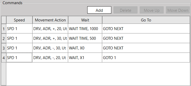
Fig. 136: Setting Servo Program Table
The operation description is shown as below:
|
Item |
Description |
||
|
Operation |
New |
After clicking, a row of commands will be added in the editing section for users to edit. |
|
|
Delete |
After clicking, delete the command currently selected by the user, and multiple selections can be deleted. |
||
|
Move Up |
After clicking, move the command currently selected by the user up one column. |
||
|
Move Down |
After clicking, move the command currently selected by the user down one column. |
||
|
Right-Click Menu |
Cut |
After clicking, cut the command currently selected by the user, and multiple selections can be cut. |
|
|
Copy |
After clicking, copy the command currently selected by the user, multiple selections can be copied。 |
||
|
Paste |
After clicking, paste the command previously copied or cut by the user. |
||
|
Insert |
After clicking, insert a row of commands at the selected position in the editor for users to edit. |
||
|
Delete |
After clicking, delete the command currently selected by the user, and multiple selections can be deleted. |
||
|
Move Up |
After clicking, move the command currently selected by the user up one column. |
||
|
Move Down |
After clicking, move the command currently selected by the user down one column. |
||
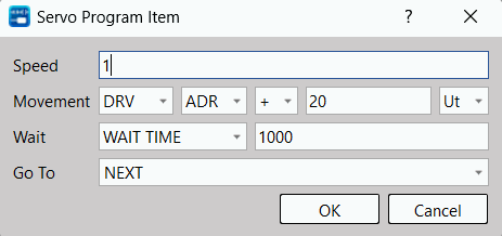
Command data description is shown as below:
|
Item |
Description |
||
|
Command |
Speed |
SPD |
The frequency or speed of the pulse output can be directly input to a constant or register (R/D). When FUN141 parameter 0=0, it is the speed; When FUN141 parameter 0=1 or 2, it is the frequency. |
|
Operation |
DRV |
Pulse Output amount. When FUN141 parameter 0=1, the unit is Ps; When FUN141 parameter 0=0 or 2, the unit is mm, Deg, Inch. There are four instruction operands:
A. ADR, relative value coordinate positioning. B. ABS, absolute value coordinate positioning.
A. ‘ + ‘, forward revolution or count up. B. ‘ − ‘, reverse or count down.
A. For Ut, the resolution is determined by FUN141 parameter 0, 3. B. For Ps, the mandatory resolution is one Ps. |
|
|
DRVC |
The usage is the same as DRV command. |
||
|
DRVZ |
As a convenient command for return-to-origin, three different methods of return-to-origin, MD0-MD2, are provided in total. |
||
|
Wait |
WAIT TIME |
WAIT TIME (unit is 0.01 second) when the pulse output is completed. When the time is up, the number of steps indicated by GOTO will be executed; constants or registers (R/D) can be input directly. |
|
|
WAIT |
WAIT for input contact signal when pulse output is completed. When the input contact signal is ON, execute the steps indicated by GOTO. |
||
|
ACT |
After the action time described by the pulse output ACT, immediately execute the number of steps indicated by GOTO; the action time (unit: 0.01 second) can be directly input into a constant or register (R/D). |
||
|
EXT |
External trigger command, when the pulse is being output (the number of pulse waves has not been sent), if the external trigger signal is activated (ON), it will immediately execute the steps indicated by GOTO. |
||
|
Go To |
GOTO |
When the condition of WAIT/ACT/EXT instruction is met, use GOTO instruction to describe the number of steps to be executed.
|
|
|
MEND |
Positioning program finished. |
||
7-4-2 Table Monitoring
The monitoring of [Servo Program Table] is shown in the figure below. Users need to be online and call the Zooming function on FUN140 to use it. The content corresponds to the command operation start register (WR) on FUN140.
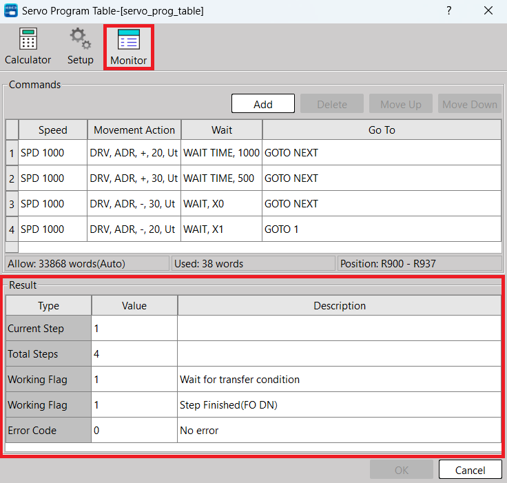
|
Item |
Description |
|
Currently Working/Stopping Steps |
If the command is being executed, the content value is the number of steps being executed (1~N); If the instruction is not being executed, the content value represents the number of steps currently stopped. |
|
Total Steps |
Steps in total |
|
Working Flag |
Corresponds to flag of WR+1 B8 =ON, suspend output. B9 =ON, wait for transition condition. B10=ON, continuous operation (total output stroke is set to 0). B12=ON, pulse output (output indication “ACT”). B13=ON, command execution error (output indication “ERR”). B14=ON, one-step positioning is completed (output indication “DN”). |
|
Error Code |
Error Codes of PSO 0-4 |
7-5 General Purpose Link Table
The main purpose of the [General Purpose Link Table] is to facilitate the user to fill in the data content of the communication command FUN151 CLINK, which corresponds to MD1/MD2. For the description of the corresponding command, please refer to the advanced manual.
7-5-1 Table Value
The table data section of [General Purpose Link Table] is as shown in the figure below. Users can edit individual commands of [General Purpose Link Table] through simple operations, and the content corresponds to the command start register (SR) on FUN151.
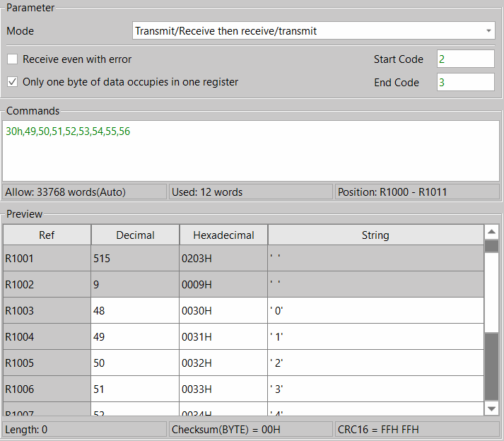
The data content description is shown as below:
|
Item |
Description |
|
|
Parameter |
Communication Mode |
[Only sending/receiving messages] When MD1 is only sending out messages, the other party does not respond; when MD2 is only receiving messages, there is no response. [Receive message after sending or Send message after accepting] MD1 is sending out a message, and then waiting to receive a response message from the other party; MD2 is receiving a message, and then sending out a response message. |
|
Receive even if a communication error occurs |
When checked, the receiving action will be performed whether there is a communication error or not. |
|
|
The register uses only one bit of data |
When checked, one data occupies one register; otherwise, two data temporarily occupy one register. |
|
|
Start Code |
Start code describing the message. |
|
|
Finish Code |
Finish code describing the message. |
|
|
Command |
Edit the content of the sent or received message. The editing content can use decimal, hexadecimal and character strings, and the data must be separated by commas or blanks. |
|
|
Preview |
Preview the message content to be sent or received. |
|
7-5-2 Table Monitoring
The monitoring of [General Purpose Link Table] is as shown in the figure below. Users need to be online and call the Zooming function on FUN151 to use it. The content corresponds to the command operation start register (WR) on FUN151.
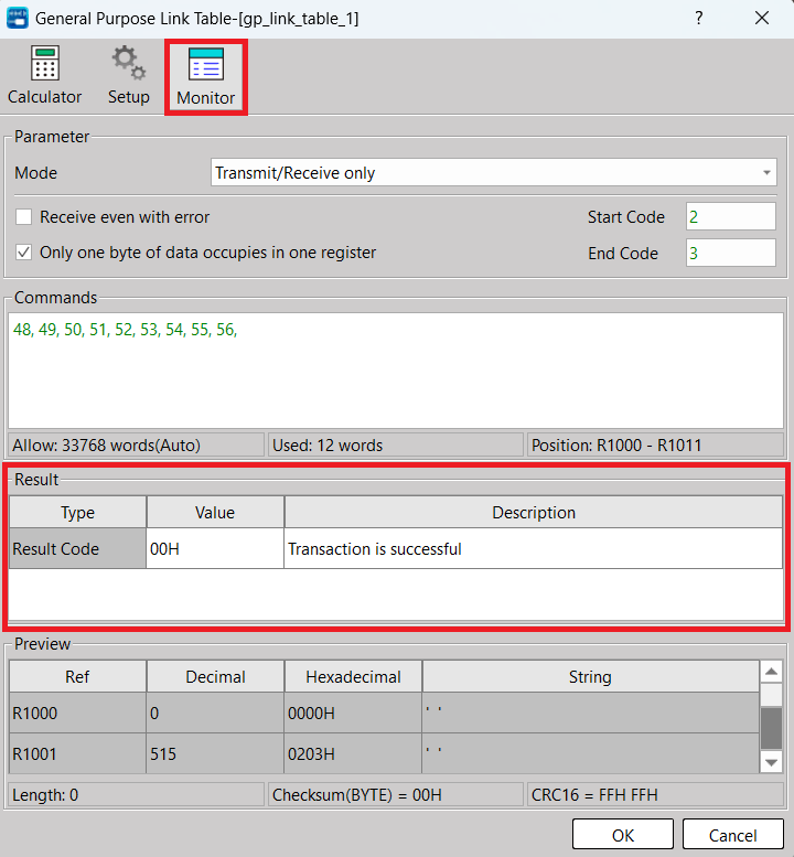
|
Item |
Description |
|
Result Code |
Shows the operating result. 00H: Normal Other values: Error |
7-6 Register Table
The register table function is mainly to provide users with fast batch writing of register values. Users can pre-plan the register table in the project, write in batches during the download process, or directly write in the new register table through online editing.
7-6-1 Table Value
The table data section of [Register Table] is as shown in the figure below, users can edit individual commands of [Register Table] through simple operations, and plan the register values in advance.
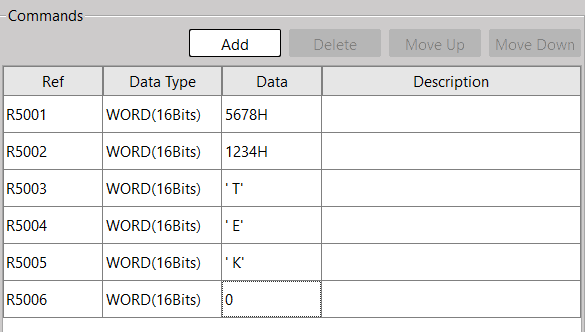
Fig. 137: Setting Register Table
The operation description is shown as below:
|
Item |
Description |
||
|
Operation |
New |
After clicking, a row of commands will be added in the editing section for users to edit. |
|
|
Delete |
After clicking, delete the command currently selected by the user, and multiple selections can be deleted. |
||
|
Move Up |
After clicking, move the command currently selected by the user up one column. |
||
|
Move Down |
After clicking, move the command currently selected by the user down one column. |
||
|
Right-Click Menu |
Cut |
After clicking, cut the command currently selected by the user, and multiple selections can be cut. |
|
|
Copy |
After clicking, copy the command currently selected by the user, multiple selections can be copied。 |
||
|
Paste |
After clicking, paste the command previously copied or cut by the user. |
||
|
Insert |
After clicking, insert a row of commands at the selected position in the editor for users to edit. |
||
|
Delete |
After clicking, delete the command currently selected by the user, and multiple selections can be deleted. |
||
|
Move Up |
After clicking, move the command currently selected by the user up one column. |
||
|
Move Down |
After clicking, move the command currently selected by the user down one column. |
||
The command data description is shown as below:
|
Item |
Description |
|
|
Command |
No. |
The address of the register to be written in batches. |
|
Data Type |
Divided into word group (16Bits) and double word-group (32Bits). |
|
|
Data |
The data to be written into the register can be filled in decimal, hexadecimal or string. In decimal, just fill in the decimal number, EX: 1234. For hexadecimal, fill in the hexadecimal number, and fill in ‘H’ at the last character. EX: 1234H. String, just fill in ASCII characters in the quotation marks, EX: ‘By’. |
|
|
Description |
Optionally fill in a description for the command. |
|
7-6-2 Table Monitoring
No monitoring function is provided to [Register Table].
7-7 Modbus Master Table
The main purpose of the [Modbus Master Table] is to facilitate the user to fill in the data content of the communication command FUN150 M-BUS. For the description of the corresponding command, please refer to the advanced manual.
7-7-1 Table Value
The table data section of [Modbus Master Table] is as shown in the figure below, users can edit individual commands of [Modbus Master Table] through simple operations, and the content corresponds to the command start register (SR) on the FUN150.
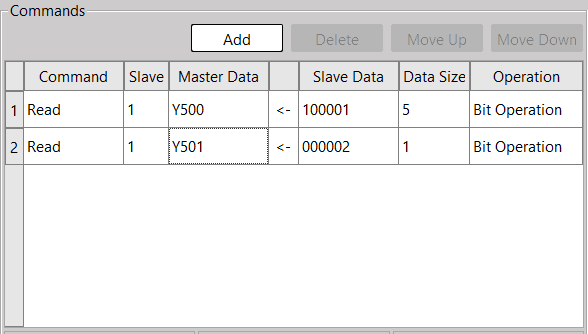
Fig. 138: Setting Modbus Master Table
The operation description is shown as below:
|
Item |
Description |
||
|
Operation |
New |
After clicking, a row of commands will be added in the editing section for users to edit. |
|
|
Delete |
After clicking, delete the command currently selected by the user, and multiple selections can be deleted. |
||
|
Move Up |
After clicking, move the command currently selected by the user up one column. |
||
|
Move Down |
After clicking, move the command currently selected by the user down one column. |
||
|
Right-Click Menu |
Cut |
After clicking, cut the command currently selected by the user, and multiple selections can be cut. |
|
|
Copy |
After clicking, copy the command currently selected by the user, multiple selections can be copied。 |
||
|
Paste |
After clicking, paste the command previously copied or cut by the user. |
||
|
Insert |
After clicking, insert a row of commands at the selected position in the editor for users to edit. |
||
|
Delete |
After clicking, delete the command currently selected by the user, and multiple selections can be deleted. |
||
|
Move Up |
After clicking, move the command currently selected by the user up one column. |
||
|
Move Down |
After clicking, move the command currently selected by the user down one column. |
||
The command data content is shown as below:
|
Item |
Description |
|
|
Data |
No. |
Display the command information of the Nth. |
|
Command |
Edit this command action as [Read] or [Write] |
|
|
Slave |
Edit the station number of the slave station to communicate. |
|
|
Master Data |
Edit the data starting address of the Master station. |
|
|
Slave Data |
Edit the data starting address of the Slave station. |
|
|
Data Size |
The data size of such command |
|
|
Operation |
Display this command as [Bit Operation] or [Word Group Operation] |
|
7-7-2 Table Monitoring
The monitoring of [Modbus Master Table] is as shown in the figure below. Users need to be online and call the Zooming function on FUN150 to use it. The content corresponds to the command operation start register (WR) on FUN150.
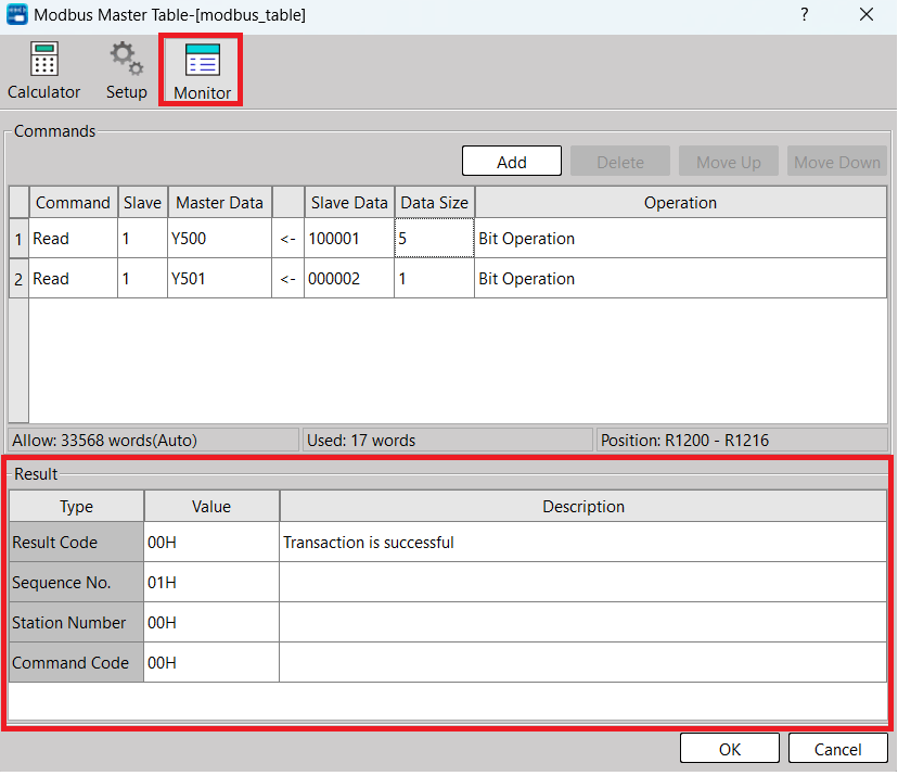
|
Item |
Description |
|
Result Code |
Shows the operating result. 00H: Normal Other values: Error |
|
Operation No. |
Indicates that the Nth transaction is in operation. |
|
Station No. |
Indicates the station number of the slave station currently in communication. |
|
Command Code |
01H: Read the status of multiple consecutive single points 0xxxxx of the slave station. 02H: Read the status of multiple consecutive single points 1xxxxx of the slave station. 03H: Read the status of multiple consecutive registers 4xxxxx of the slave station. 04H: Read the status of multiple consecutive registers 3xxxxx of the slave station. 05H: Write a single-point 0xxxxx status to the slave. 06H: Write single register 4xxxxx data to the slave station. 0FH: Write consecutive multiple single points 0xxxxx status to the slave station 10H: Write consecutive multiple registers 4xxxxx data |
Tip: press ← → to switch chapters, Ctrl+K to search