|
⚠Danger |
|
This section describes the servo and cam related configuration methods. By combining the image-base display and the user-friendly interface, it allows the user to control the setting method more quickly and more efficiently.
To understand the detailed operation method of motion control, please refer to the relevant manuals.
Described below is the operation method of different motions.
9-1 Motion Network
After implementing the setting axis in the “Motion Network,” the user will be allowed to set the information of the connected slave station (virtual axis).
Setting process:
By clicking [Motion] → [Motion Network] → “Right mouse button” → [Motion Network] in project management row or clicking [Project] → [Motion] → [Motion Network] → [Motion Network], it allows the user to open the [Motion Network] page.
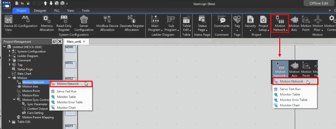
Fig. 156: Motion network setting page
- Importing ESI file
Import the “EtherCAT” slave station data by clicking “Import ESI file.” For details of ESI file, please contact your server dealer.
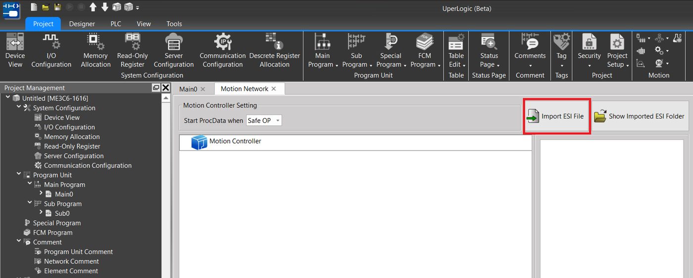
Fig. 157: Importing slave station data
- Joining slave station
After being imported, the Slave Station Option List will appear. Double-click or scroll down to [Motion Controller] list, and the joining will be allowed.
※ The indicated sequence is the communication sequence.
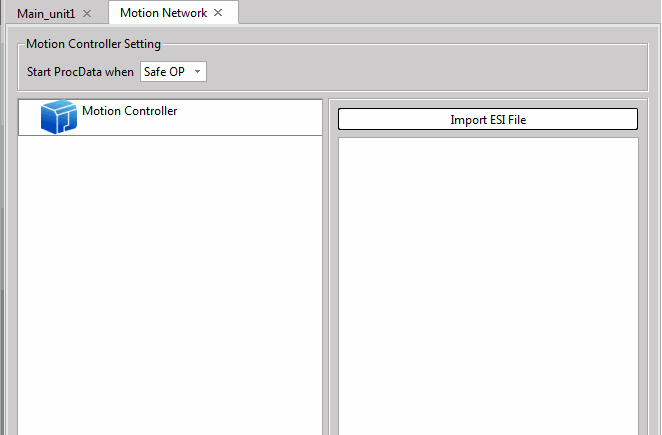
Fig. 158: Communication sequence list
- Other functions
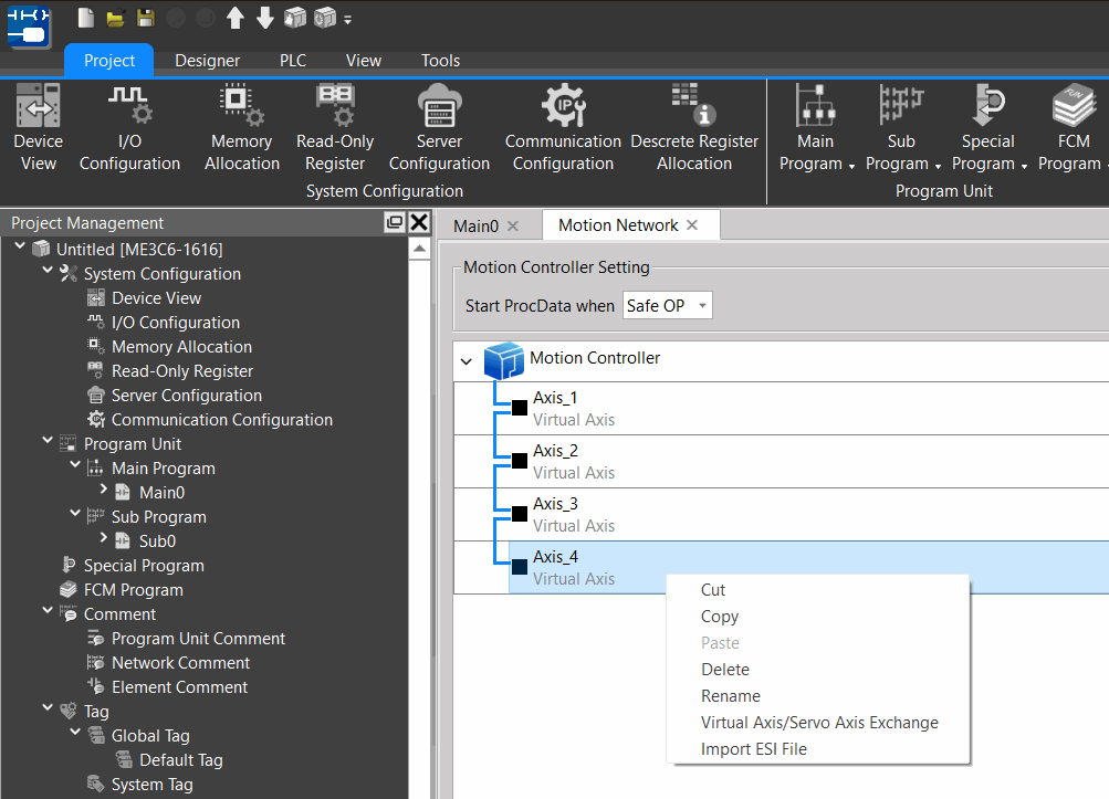
Fig. 159: Other functions
|
Function |
Description |
|
Cut |
At the axis that will be cut, click the right mouse button and then select [Cut] in the menu. |
|
Copy |
At the axis that will be copied, click the right mouse button and then select [Copy] in the menu. |
|
Paste |
At the position that will be pasted, click the right mouse button and then select [Copy] in the menu and you may paste the axis being copied or clipped. |
|
Delete |
At the axis that will be deleted, click the right mouse button and then select [Delete] in the menu. |
|
Rename |
At the axis that will be renamed, click the right mouse button and then select [Rename] in the menu. |
|
Real Axis-Virtual Axis Conversion |
At the axis that will be converted, click the right mouse button and then select [Real Axis-Virtual Axis Conversion] in the menu. |
|
Import ESI file |
At the axis that will be imported, click the right mouse button and then select [Import ESI File] in the menu and you can start the importing. |
|
Change Sequence |
Drag the Slave Station to be changed to the intended position. |
Parameter
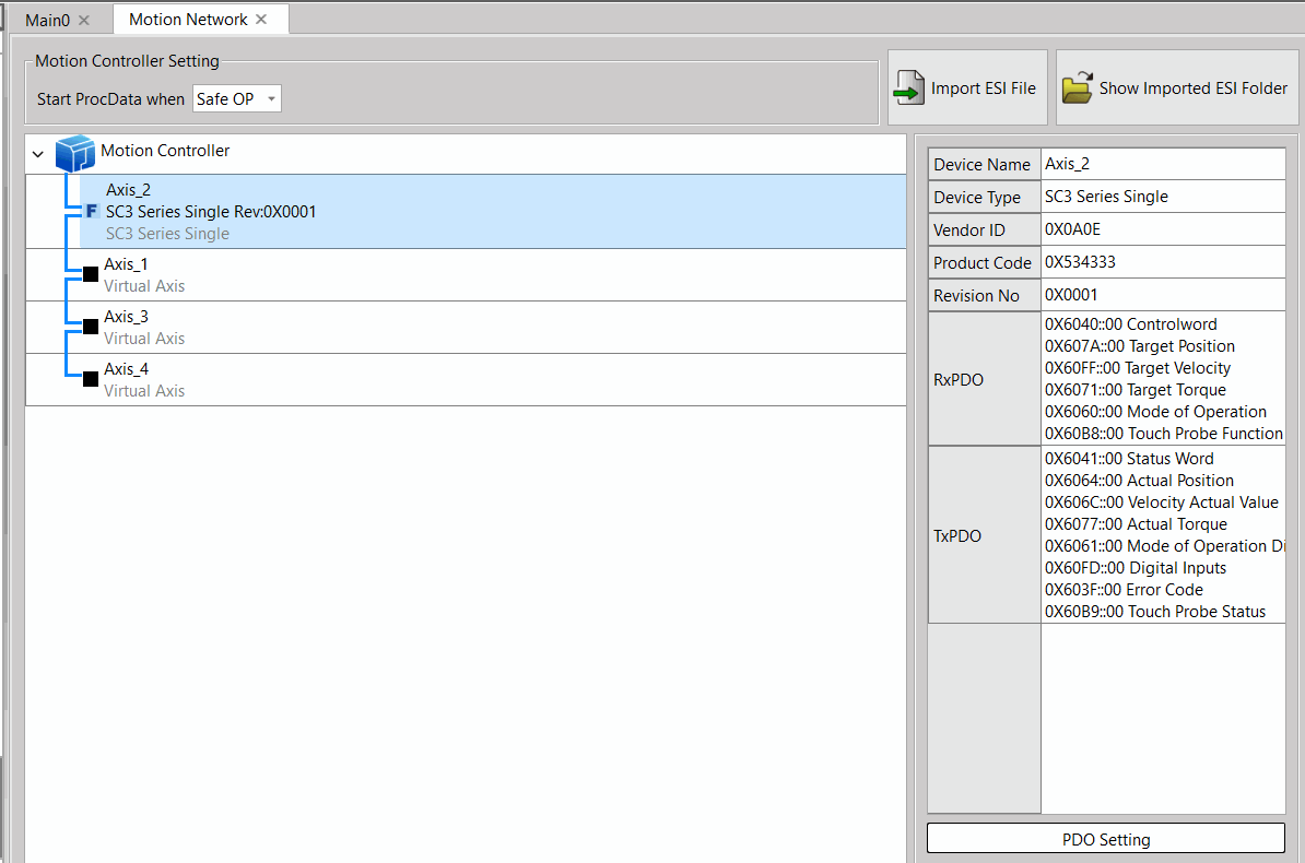
Fig. 160: Parameter setting page
Current fixed PDO setting as below:
|
PDO Type |
Item |
Name |
|
RxPDO |
0x6040 |
Controlword |
|
0x607A |
Target position |
|
|
0x60FF |
Target velocity |
|
|
0x6071 |
Target Torque |
|
|
0x6060 |
Mode Of Operation |
|
|
0x60B8 |
Touch Probe Function |
|
|
TxPDO |
0x6041 |
Status Word |
|
0x6064 |
Actual Position |
|
|
0x606C |
Velocity actual value |
|
|
0x6077 |
Actual Torque |
|
|
0x6061 |
Mode Of Operation Display |
|
|
0x60FD |
Digital inputs |
|
|
0x603F |
Error code |
|
|
0x60BA |
Touch Probe Pos1 Pos Value |
|
|
0x60BC |
Touch Probe Pos2 Pos Value |
Table 19: PDO setting table
Currently, the system uses 3 kinds of modes. Listed below are the parameters and the unit required for SC3 series.
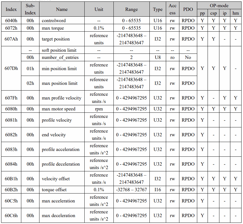
Table 20: Synchronous Cycle Position Control Mode Table
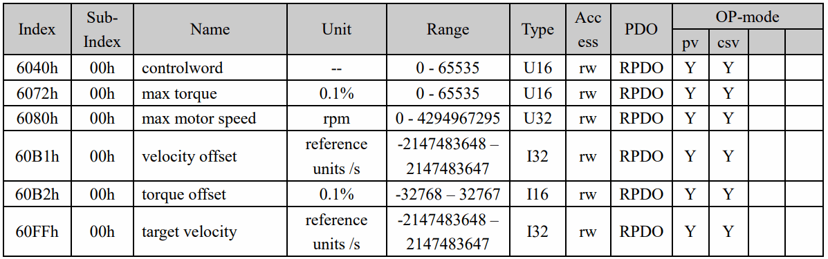
Table 21: Synchronous Cycle Velocity Control Mode Table
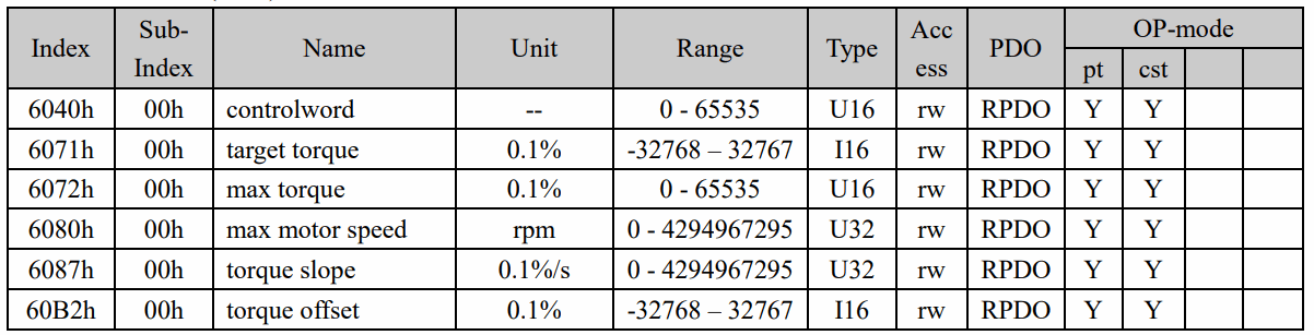
Table 22: Synchronous Cycle Torque Control Table
9-1-1 Servo Test Run
Click [Motion] → [Motion Network] → “Right mouse button” → [Servo Test Run] in project management row.
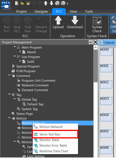
Fig. 161: Servo Test Run
Or select [PLC] → [Motion] → [Motion Network] → [Servo Test Run] from the ribbon tag page.
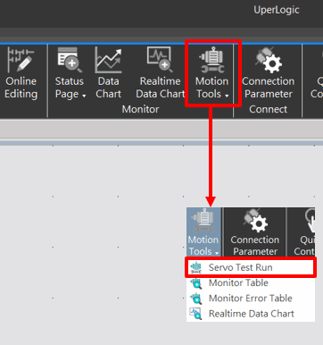
Fig. 162: Servo Test Run
Select the Test Run axis:
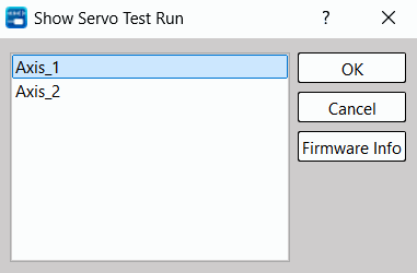
Fig. 163: Selecting the Test Run axis
Indicated below is the Test Run page and it comprises three types of control modes (Position, Velocity, Torque):
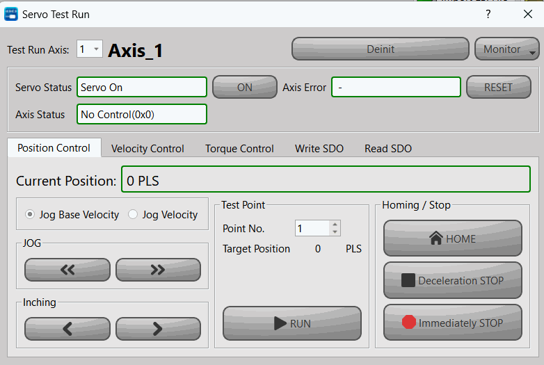
Fig. 164: Position Control Mode
After turning on the test run function, the user must first click Initialization > Servo ON, and then the corresponding control test can be carried out after no abnormalities are found.
Note: The test run function can only be executed when the EtherCAT connection is normal and enabled (Servo on).
|
Introduction of Motion Test Run Basic Function |
|
|
Function |
Description |
|
Test Run Axis |
Display the name of current test run axis. |
|
Initialize&Deinitialize |
After clicking, it will be possible to initialize or deinitialize the axis currently in test run. |
|
Monitor |
Provide shortcut buttons for monitoring tables and monitoring graphs for users to monitor. Users can also find monitoring tables and monitoring graphs through the motion graph on the top or the project management on the left. Note: Users can refer to the chapters of Watch Table and Watch Graph for details. |
|
Servo Status (ON/OFF) |
The current status of the axis will be provided in the green box, and the user can control it through the right button. |
|
Axis Error |
The error information of the current axis will be provided in the green box. If “–“ is displayed, there is no error, and the user can reset the error through the “Reset” button on the right. |
|
Axis Status |
The status information of the current axis will be provided in the green box. |
|
Position Control |
Provide users with functional tests such as JOG, movement point and HOME return, which will be introduced in detail in subsequent chapters. Note: Motion points can only perform single-axis motion control, and cannot perform tests such as linear or arc interpolation. |
|
Speed Control |
It provides users with speed control, which will be introduced in detail in subsequent chapters. |
|
Torque Control |
It provides users with torque control, which will be introduced in detail in subsequent chapters. |
- Position Control
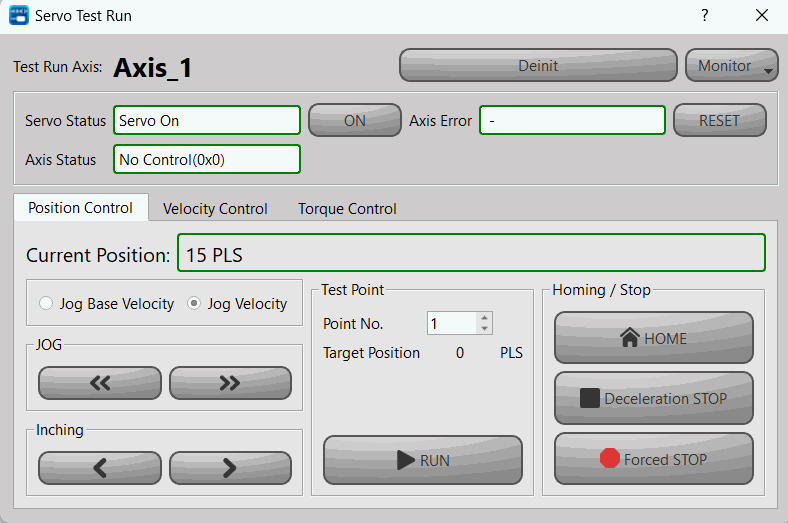
The screen of the position control for trial run is as shown in the figure below. The position control provides a total of three control methods: “JOG”, “Test Point” and “HOME Return”, which will be explained one by one below.
-
- JOG Fintion Description
The control of the JOG mode is on the left side of the position control, and the user can perform forward and backward tests by selecting different modes, and view it from the current position.
|
Mode Collocation |
Description |
|
JOG Base Speed & JOG |
After clicking, it will move at the JOG start speed set by the motion axis until the user releases it, and the servo operation will stop immediately. (Same as JOG mode 0) |
|
JOG Base Speed & JOG |
After clicking, it will move at the JOG start speed set by the motion axis until the JOG distance set by the motion axis is executed, and the servo operation will be stopped immediately. (Same as JOG mode 1) |
|
JOG Speed & JOG |
After clicking, it will move forward from the JOG start speed set by the motion axis, and accelerate to the JOG speed set by the motion axis with the JOG acceleration set by the motion axis, until the user releases it, and decelerate to the JOG deceleration set by the motion axis After the set JOG start speed, stop the servo operation immediately. |
|
JOG Speed & JOG |
After clicking, it will advance from the JOG start speed set by the motion axis, and accelerate to the JOG speed set by the motion axis with the JOG acceleration set by the motion axis, until the JOG distance set by the motion axis is executed, and decelerate with the JOG set by the motion axis. After the speed decreases to the JOG start speed set by the motion axis, the servo operation will stop immediately. (Same as JOG mode 3) |
-
- Test Point Function Description
Test Point provides the user with a test point table to see if the setting is correct. Before the test run, the user must first set the corresponding test point in the motion point setting, and then the test run can be performed.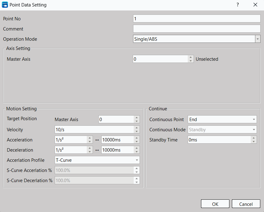
Operation Mode:
During the test run, only single-axis motion control is provided, and other controls such as linear or arc interpolation cannot be performed.
Axis Setting (Master Axis): To select the same axis No. as in the test run.
Motion Setting: Select the target position to be moved, as well as the axis speed and acceleration and deceleration, the initial speed will be the same as the motion axis setting.
Continue: Set whether there is a need to continue to the next point.
Users can test according to the above settings, or refer to the chapter of movement points for more details of the settings.
-
- HOME Return Function Description
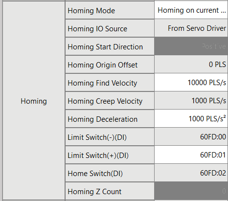
Provide the user with the test of homing, the operation mode is the same as the homing set by the motion axis. When the user does not set the origin, the motor will continue to run. At this time, the function of HOME return can be stopped through the function of deceleration and stop. If an abnormality is about to occur, the motor can also be stopped by forced stop
- Velocity Control
The screen of the test run velocity control is as shown in the figure below. In the test velocity mode, please input the velocity command and torque limit first. After starting, the motor will quickly reach the velocity set by the velocity command, and keep running at the same velocity until the user stops or the torque limit is exceeded.
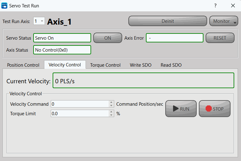
Fig. 165: Velocity Control Mode
- Torque Control
The screen of the test run torque control is as shown in the figure below. In the test torque mode, please input the torque command and speed limit first. After starting, the motor will quickly reach the velocity set by the speed command, and keep running at the same velocity until the user stops or exceeds the speed limit.
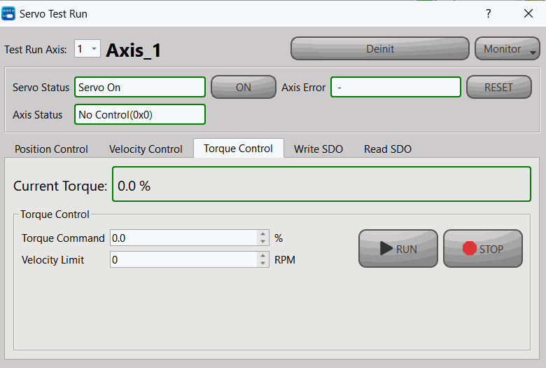
Fig. 166: Torque Control Mode
Note: In order to avoid accidents, when the load is not increased, do not set the torque command too large, and set a velocity limit within a safe range, so as to avoid the machine from not reaching the corresponding torque because there is no load, and then continue to accelerate, resulting in errors.
9-1-2 Monitor Table
Click [Motion] → [Motion Network] → “Right mouse button” → [Monitor Table] in project management row, or you may select [PLC] → [Motion Network] → [Monitor Table] from the ribbon tag page.
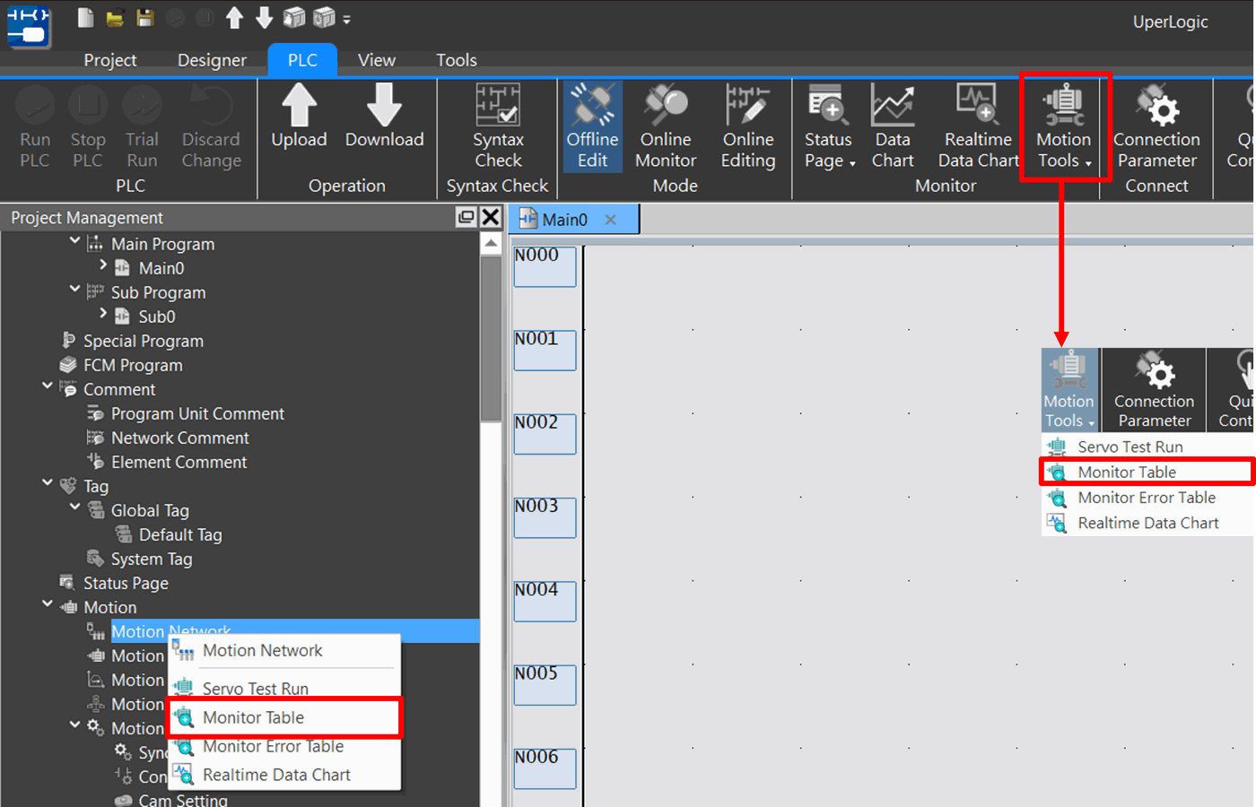
Fig. 167: Motion monitoring table
Provided below is the window showing the opened Motion Monitor Table. If there isn’t any axis in the figure, please set up the axis through [Motion Network].
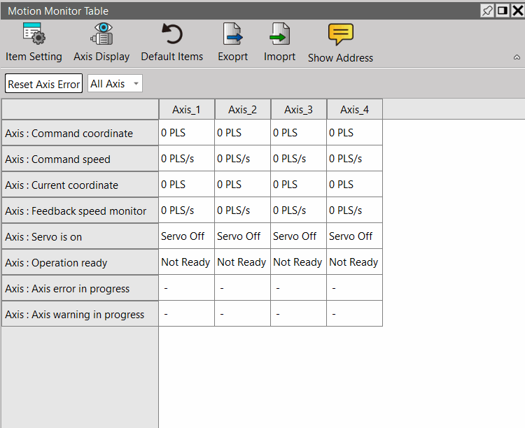
Fig. 168: Motion Monitor Table
Click [Item Setting], and you may select the object to be monitored.
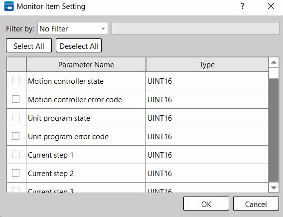
Fig. 169: Selecting the item to be monitored
Click [Axis Display], and you may select the axis to be displayed.
Click [Export] and [Import], and the system will show the setting required for exporting and importing the Motion Monitor Table.
9-1-3 Monitor Error Table
Click [Motion] → [Motion Network] → “Right mouse button” → [Monitor Error Table] in project management row, or select [PLC] → [Motion Network] → [Monitor Error Table] from the ribbon tag page.
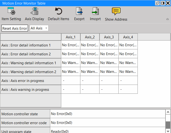
Fig. 170: Motion eroor monitoring table
9-1-4 Realtime Data Chart
Click [Motion] → [Motion Network] → “Right mouse button” → [Realtime Data Chart] in project management row, or select [PLC] → [Realtime Data Chart] from the ribbon tag page, or select [PLC] → [Motion Network] → [Realtime Data Chart].
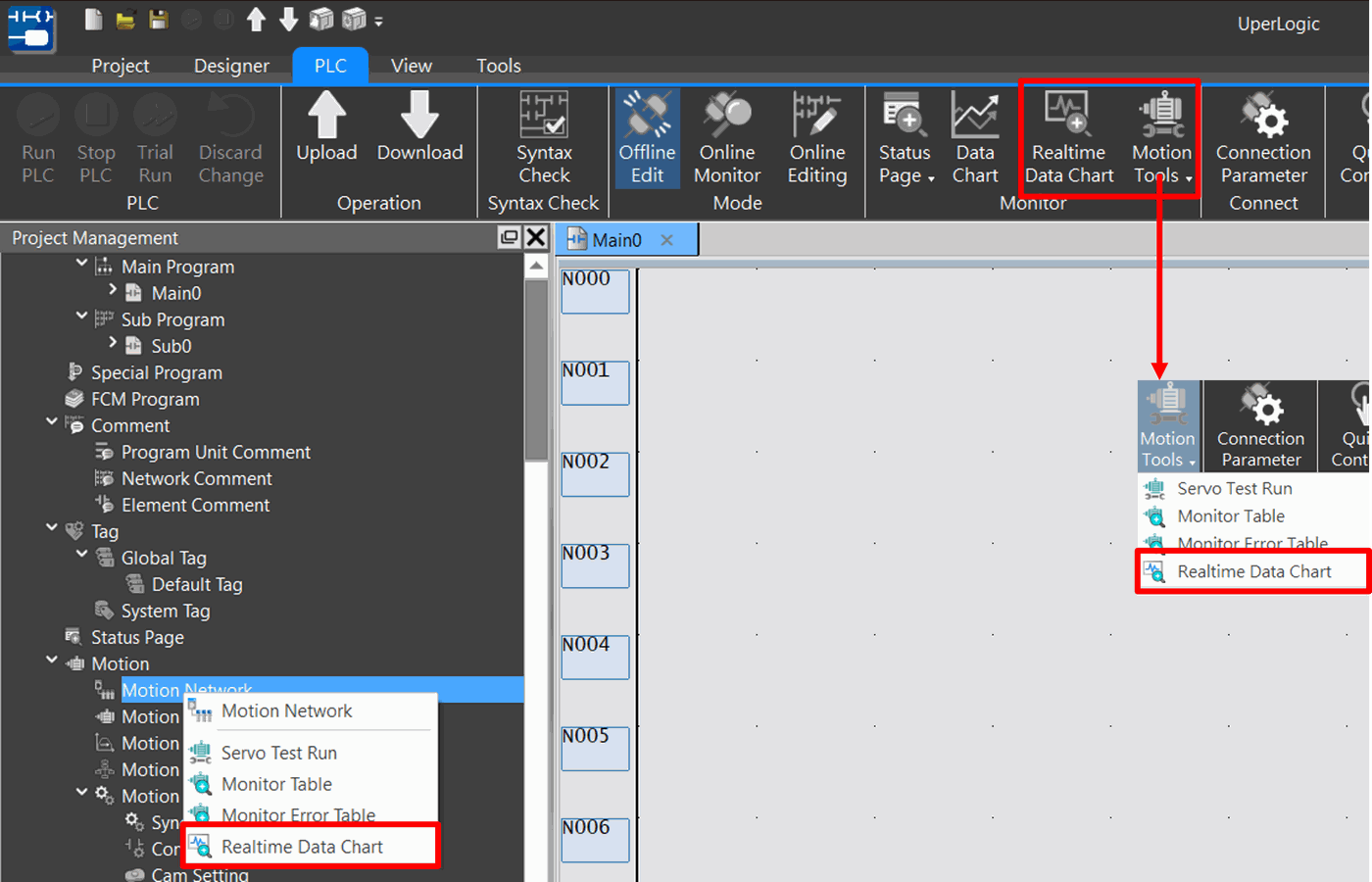
Fig. 171: Realtime Data Chart
Provided below is the window showing the opened Motion Realtime Data Chart.
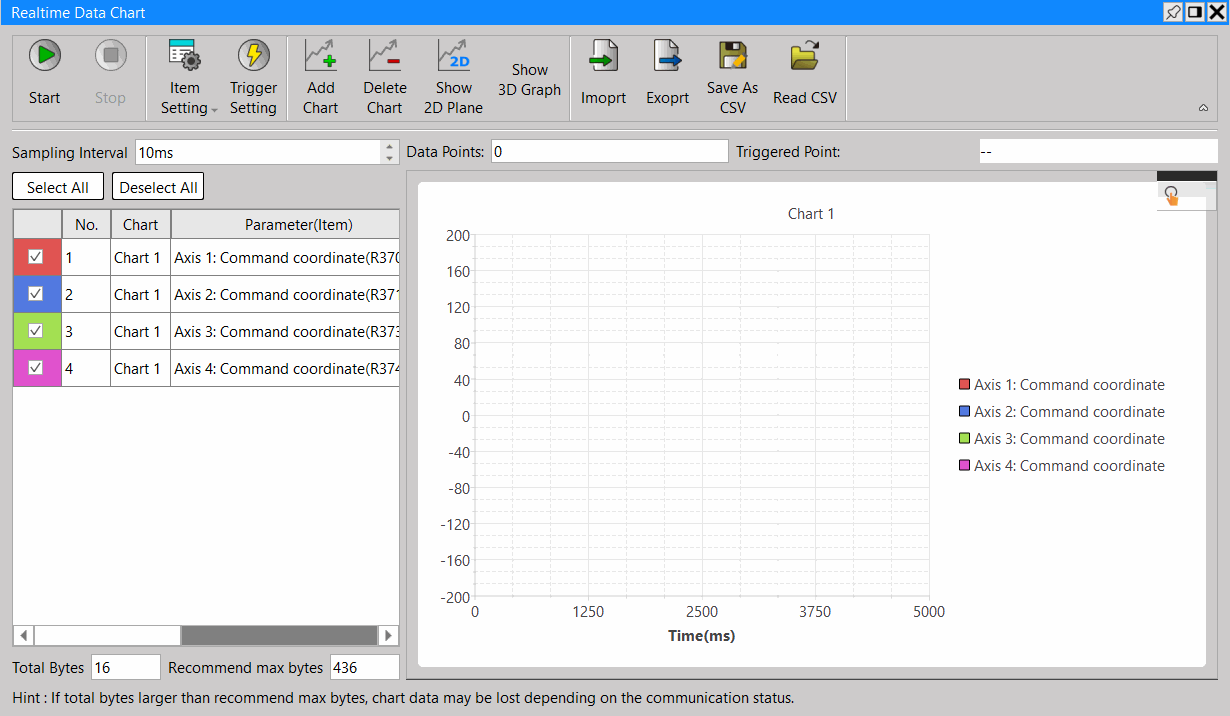
Fig. 173: Motion monitoring page
9-2 Motion Axis
- Setting process
Click [Project] → [Motion] → [Motion Axis] in function toolbar, or you may select [Project] → [Motion Axis] in project management window and then double click the left mouse button to open the setting page.
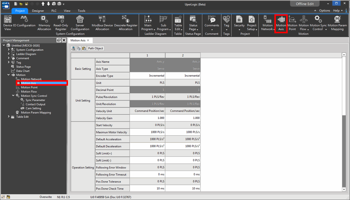
Fig. 173: Motion axis setting
- Setting method
After setting adding axis in [Motion Axis], the system will add the desired axis automatically by clicking the table setting directly.
- Display setting
By clicking [Axis Display Setting], it can be set as displaying the axis for users to create the desired axis more easily.
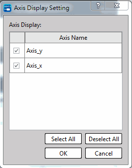
Fig. 174: Axis Display Setting
- Parameter
Click the corresponding parameter position, and it allows the user to modify the parameter being created for such axis. For detailed description of parameters, please refer to Chapter 4 of Motion Control User Manual.
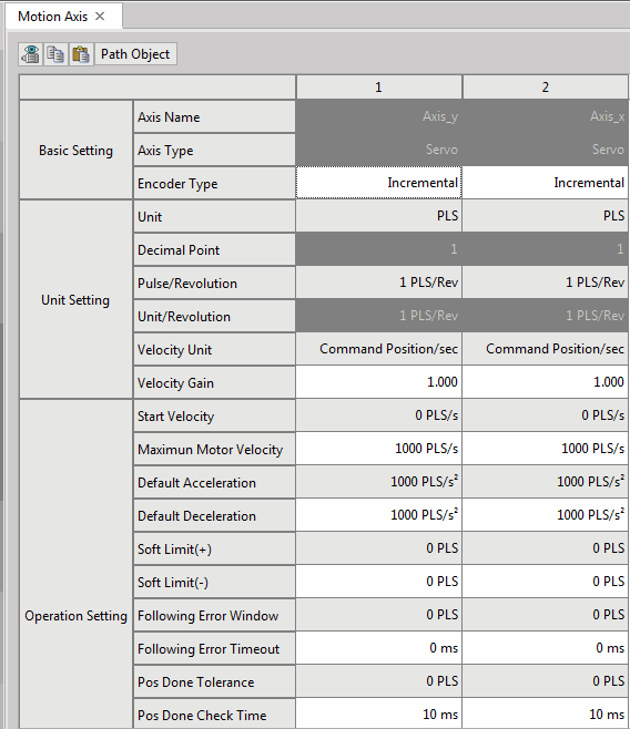
Fig. 175: Axis Display Setting
9-3 Motion Point
- Setting process
Click [Project] → [Motion] → [Motion Point] in function toolbar, or you may select [Project] → [Motion Point] in project management window and then double click the left mouse button to open the setting page.
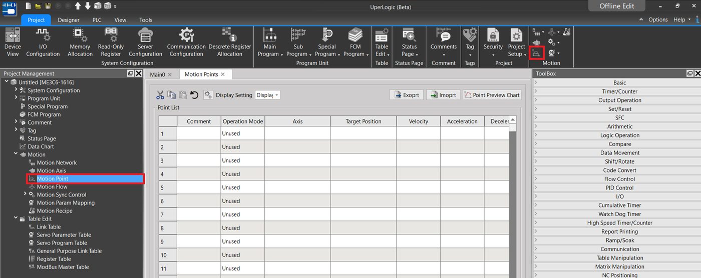
Fig. 176: Motion point setting
You may also click [Point Preview Chart] in the working window to open the preview page.
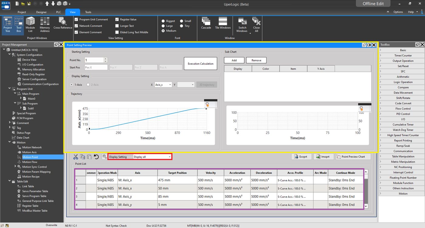
Fig. 177: Motion point preview page
|
Item |
Description |
|
Display Setting |
Display all: Display all points (256 points until now) Display continuing point: Display the continuing points only and “Starting point” will be displayed on right-hand side for selection. |
|
Point Preview Chart |
Show the window highlighted by upper side yellow box for simulation reference. |
|
Setting Page |
From the purple block at upper side of the desired point parameter, select the motion point to be created. After double clicking, you may start setting the point data. |
Table 23: Descriptive table of motion Point Preview Chart
- Setting page parameters
Through the point data setting function, it allows the user to modify the parameter setting of the motion point. For detailed parameter description, please refer to Motion Control User Manual.
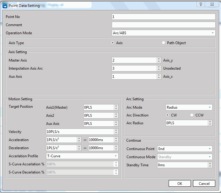
Fig. 178: Point Data Setting
- Point Preview Chart
Click [Point No.] and then select the motion point to be previewed. After setting the [Start Pos], click [Execution Calculation] and the preview map of such motion point will be displayed at the lower side track. For detailed setting, please refer to Motion Control User Manual.
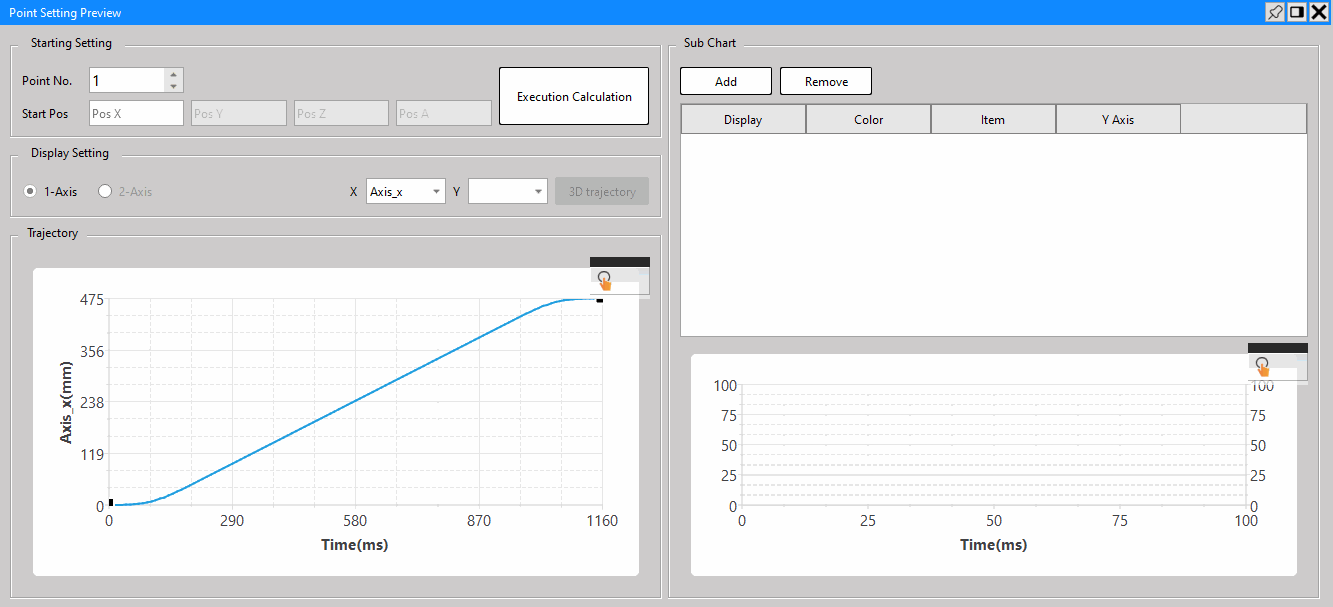
Fig. 179: Point Preview Chart setting
- Trajectory display control
By clicking the  icon, you may open the scroll-down menu containing the [Trajectory Display Control] option. Indicated in the figure below are the functions.
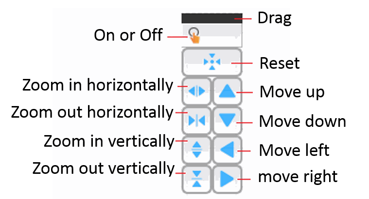
Fig. 180: Trajectory display control
9-4 Motion Flow
- Setting process
Click [Project] → [Motion] → [New Motion Flow] in function toolbar, or you may select [Project] → [Motion] → [Motion Flow] in project management window and then double click the right mouse button to add new motion flow.
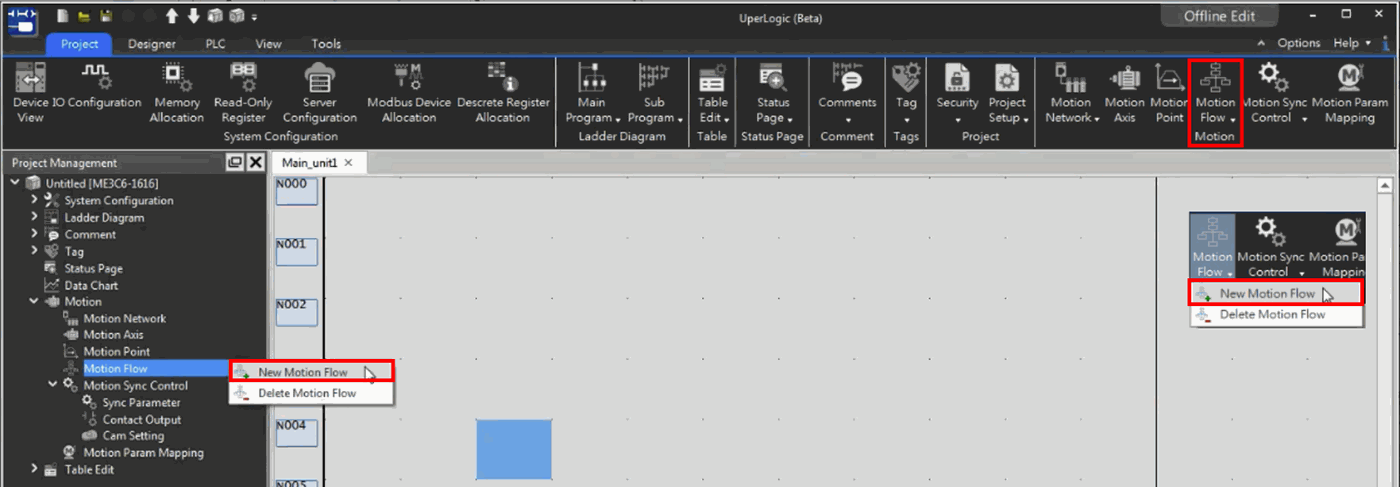
Fig. 181: Adding motion process
In Motion Flow options, click the right mouse button and the flow will be renamed.
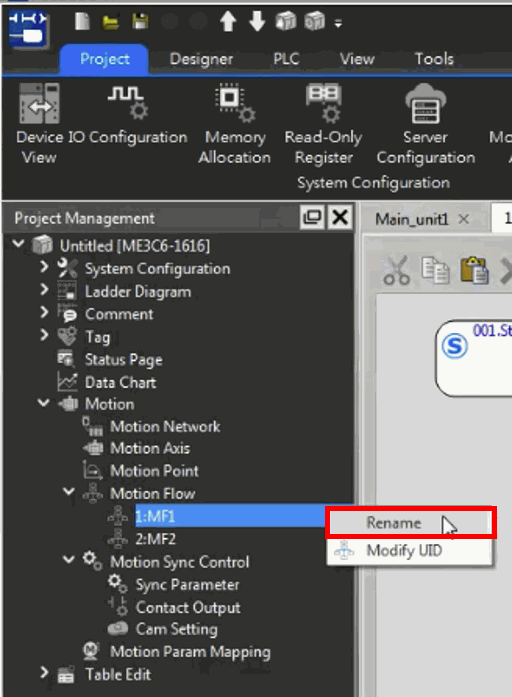
Fig. 182: Renaming motion flow
- Adding flow block
|
Description |
Icon |
|
Simply drag the right-side toolbox to the preview window. |
|
|
When dragging the block to the window, both will be connected by aligning red box with Node. |
|
|
After selecting the block, press “F” and you will be allowed to add the imported block. |
|
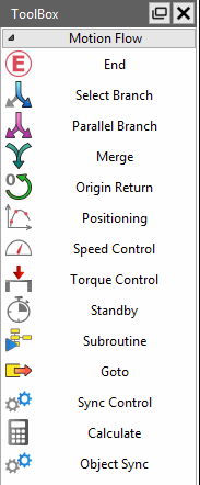
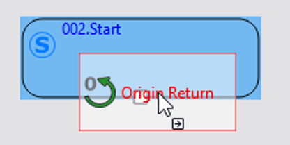
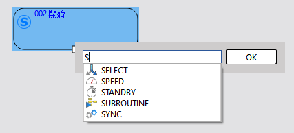
Table 24: Flow block adding setting table
- Deleting flow block
Click block (multiple choices available) and then press “Delete.”
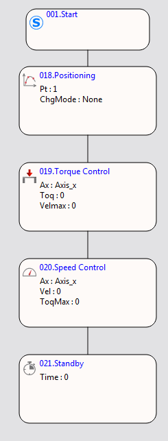
Fig. 183: Deleting flow block
- Adding link
Press the contact and then drag it to the point to be connected.
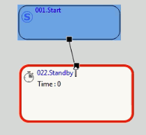
Fig. 184: Adding link for fkow block
- Deleting link
Click the respective line and then press “Delete” and the link will be deleted.
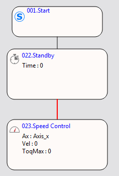
Fig. 186: Deleting flow block link
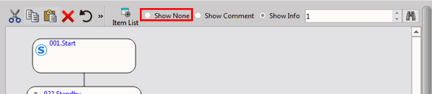
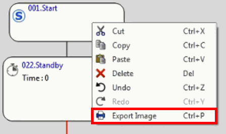
- Others
|
Item |
Description |
|
Show None |
|
|
Show Comment |
|
|
Show Info |
|
|
Cut |
|
|
Copy |
|
|
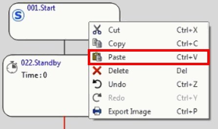
Paste |
|
|
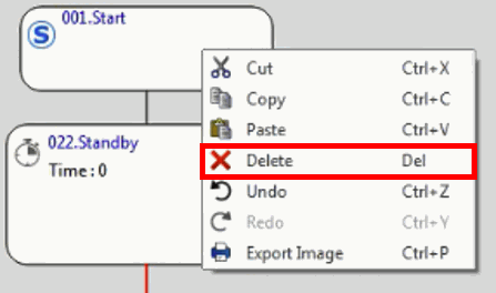
Delete |
|
|
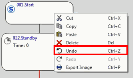
Undo |
|
|
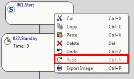
Redo |
|
|
Export Image |
|
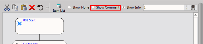
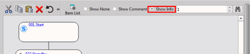
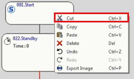
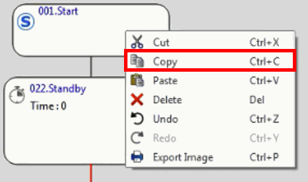
Parameter
Flow setting block introduction.
Basic Description
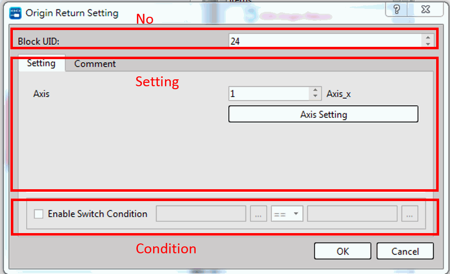
Fig. 186: Flow block basic description
Action number: The number coded for such action. It represents the ID of the action currently displayed by Register R36884–R36890.
Action setting: The setting page of each action. After completing the action, Register R36891–R36906 will be displayed as “2” (action completed).
To next action condition: If such function is used, the system will go to next action block after meeting the conditions.
Note: Taking the GoTo for example (presuming the conditions are met → No. 1; otherwise → No. 3), the system has determined to proceed to next action block (if GoTo No. 1) when completing the current action. If the system has set up the conditions for proceeding to next action block, then the direction will remain unchanged (the system will not GoTo No.3 at this time) even though the system has changed the GoTo conditions again (the conditions for GoTo No. 1 no longer exist).
Start
Select Branch
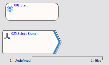
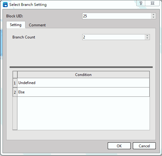
Fig. 187: Selecting branch
After selecting the branch blocks, the system will execute the inspection from left to right in order to execute the first branch that meets the conditions. The rightmost means “ELSE” and the system will execute the process blocks at the rightmost side if failing all of the conditions. Currently, the maximum number has been set up to 16 branches.
|
Item |
Description |
|
Branch Count |
Number of branch blocks (1–16) |
|
Condition |
Branching execution conditions |
Parallel Branch
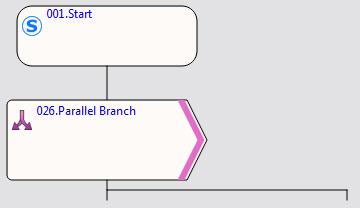
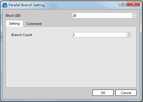
Fig. 188: Parallel branches
After executing the parallel branch blocks, the system will execute the process blocks according to the quantity set for the branch blocks. Currently, the maximum number has been set up to 16 branches.
|
Item |
Description |
|
Branch Count |
Number of branch blocks (1–16) |
Merge
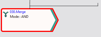
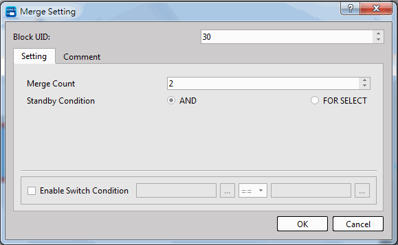
Fig. 189: Merge setting
The selected branches and the parallel branches shall be displayed in pairs. In this case, it means the branch setting is finished.
|
Item |
Description |
|
Merge Count |
Composite quantity (1–6) |
|
Standby Condition |
1. AND: For parallel process 2. FOR SELECT: For block selections |
Origin Return
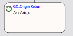
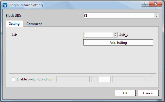
Fig. 190: Origin Return setting
After selecting the desired axis, the system will execute the Origin Return according to the axis setting pattern.
|
Item |
Description |
|
Axis |
Axis_conveyor |
Positioning
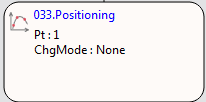
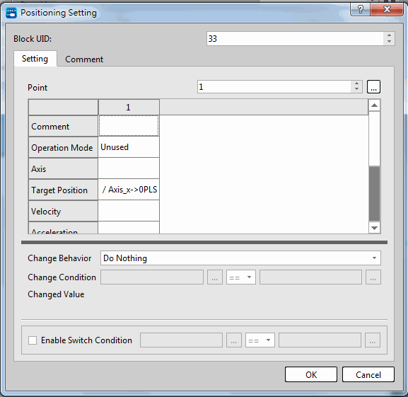
Fig. 191: Positioning setting
Select the parameters of the corresponding points and then start the positioning.
|
Item |
Description |
|
Point |
The points to be controlled |
|
Change Behavior |
Do Nothing Change Current Coordinates Change Speed Stop after moving for certain distance |
|
Change Condition |
Change the desired parameters after meeting such condition during the positioning process. |
|
Changed Value |
The value to be changed. |
Speed Control
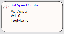
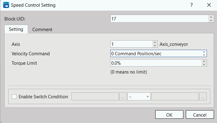
Fig. 192: Speed control setting
Select the corresponding axis and then start the speed control according to the set value.
|
Item |
Description |
|
Axis |
The axis requiring speed control. |
|
Velocity Command |
The speed to be achieved (min-1) |
|
Torque limit (0.01%) |
Torque limit and “0” means unlimited. |
Torque Control
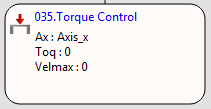
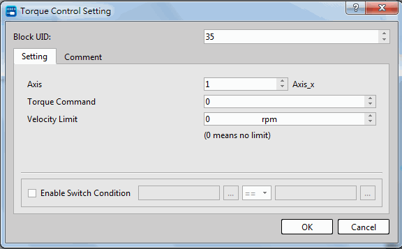
Fig. 193: Torque control setting
Select the corresponding axis and then start the torque control according to the set value.
|
Item |
Description |
|
Axis |
The axis requiring speed control. |
|
Torque Command |
The torque to be achieved. |
|
Velocity Limit |
Speed limit and “0” means unlimited. |
Standby
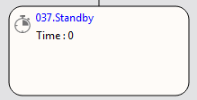
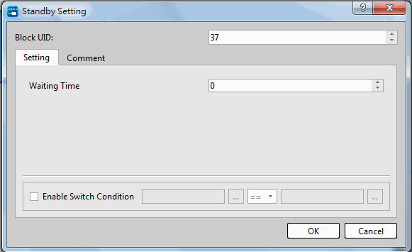
Fig. 194: Standby setting
Based on the conditions being created for the mode, GoTo next process block after meeting the intended conditions.
|
Item |
Description |
|
Waiting Time |
The created waiting time, expressed in “ms” as the unit. |
|
Enable Switch Condition |
Switch conditions |
Subroutine
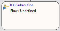
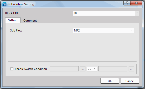
Fig. 195: Subroutine setting
When running to this process block, you may execute other process.
|
Item |
Description |
|
Sub-program |
Select the process to be executed. |
GoTo
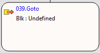
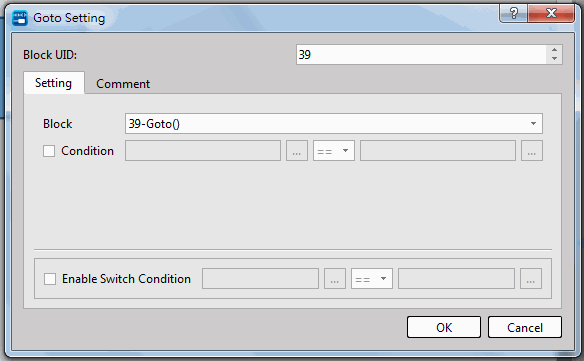
Fig. 196: GoTo setting
When running to this process block, you may execute the GoTo for entering other blocks of this process or finish the process directly.
|
Item |
Description |
|
Block |
Select the process block of this process or finish the process. |
|
Condition |
Select the GoTo for entering the created setting block after meeting the conditions. |
Synchronization
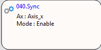
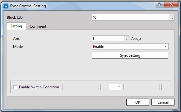
Fig. 197: Synchronization control setting
Enable or disable the designated axis synchronization control.
|
Item |
Description |
|
Axis |
Start or close the synchronized axis. |
|
Mode |
Start or close the synchronization control. |
9-5 Motion Sync Control
Click [Project] → [Motion] → [Motion Sync Control] in function toolbar and then click the left mouse button to open the scroll-down menu in order to select the page that will be set. You may select the page to be created by clicking [Project] → [Motion Sync Control] in project management window.
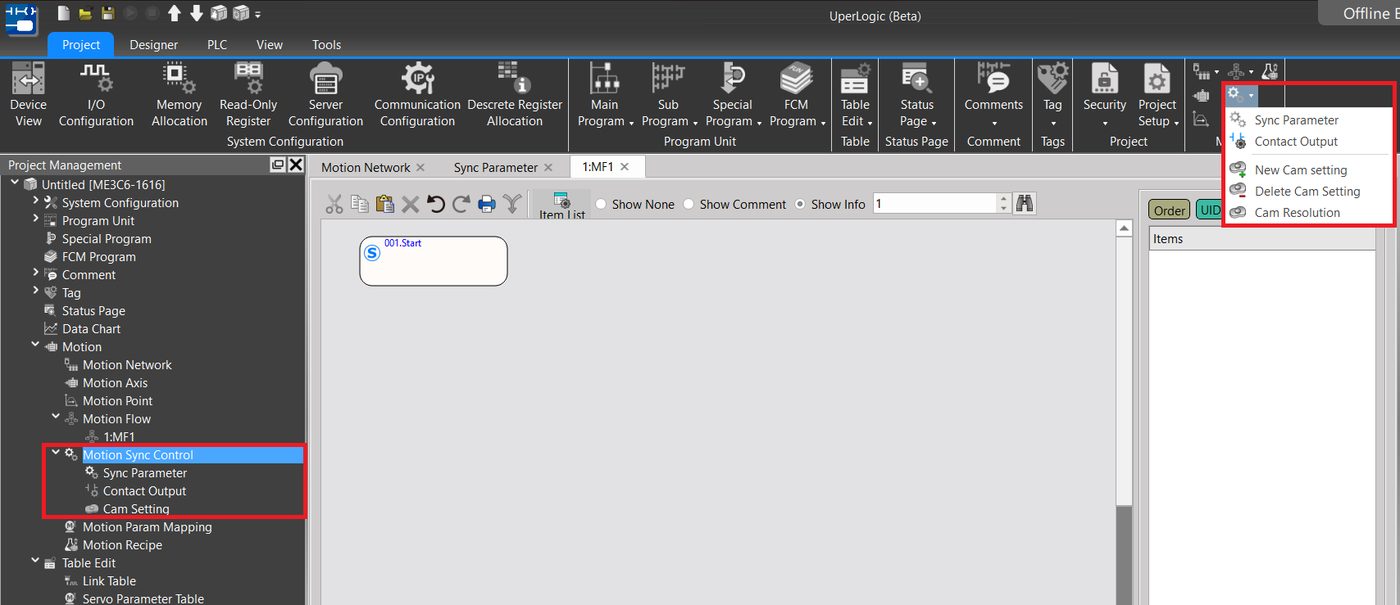
Fig. 198: Motion synchronization setting
9-5-1 Sync Parameter
Click [Sync Parameter] in scroll-down menu of [Motion Sync Control], or you may select [Project] → [Motion Sync Control] in project management window. Next, click the left mouse button to open the scroll-down menu to select [Sync Parameter].
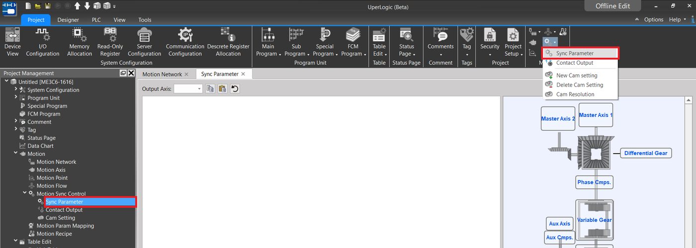
Fig. 199: Synchronize parameter setting
You may use the output axis to select the synchronize parameters of the axis that will be created. You may also use the copy and paste function next to the [Output Axis] for presetting the corresponding setting process. For detailed setting, please refer to Motion Control User Manual.
9-5-2 Contact Output (to be released)
Click [Sync Parameter] in scroll-down menu of [Motion Sync Control], or you may select [Project] → [Motion Sync Control] in project management window. Next, click the left mouse button to open the scroll-down menu to select [Contact Output].
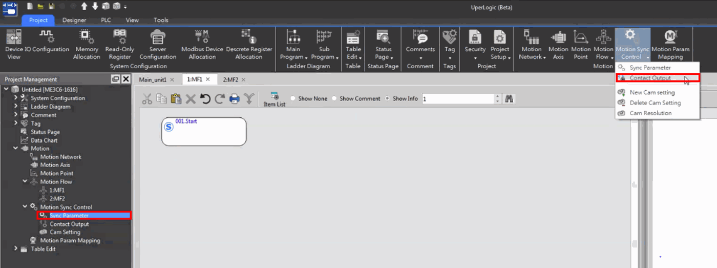
Fig. 200: Contact Output setting
For detailed setting of synchronize contact, please refer to Motion Control User Manual.
9-5-3 Cam setting
Click the scroll-down menu of [Motion Sync Control] and you will be allowed to select the required cam setting. You may also click [Project] → [Motion Sync Control] in project management window and then click the right mouse button to open [ New Cam setting] in the scroll-down menu.
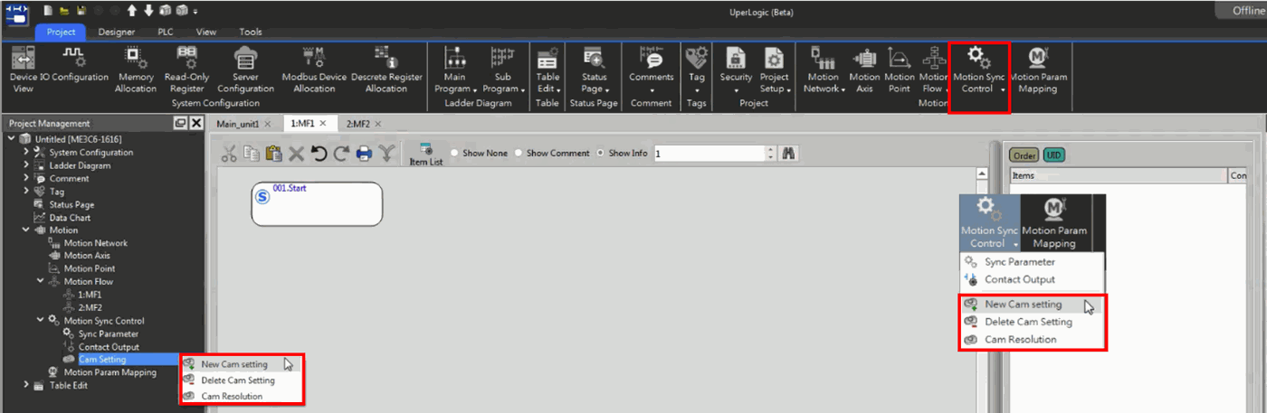
Fig. 201: Cam setting
New Cam setting
Click the scroll-down menu of [Motion Sync Control] and you will be allowed to select [New Cam setting] or you may select [Project] → [Motion Sync Control] → [Cam setting] in project management window. Next, click the right mouse button to open the scroll-down menu and then select [New Cam setting].
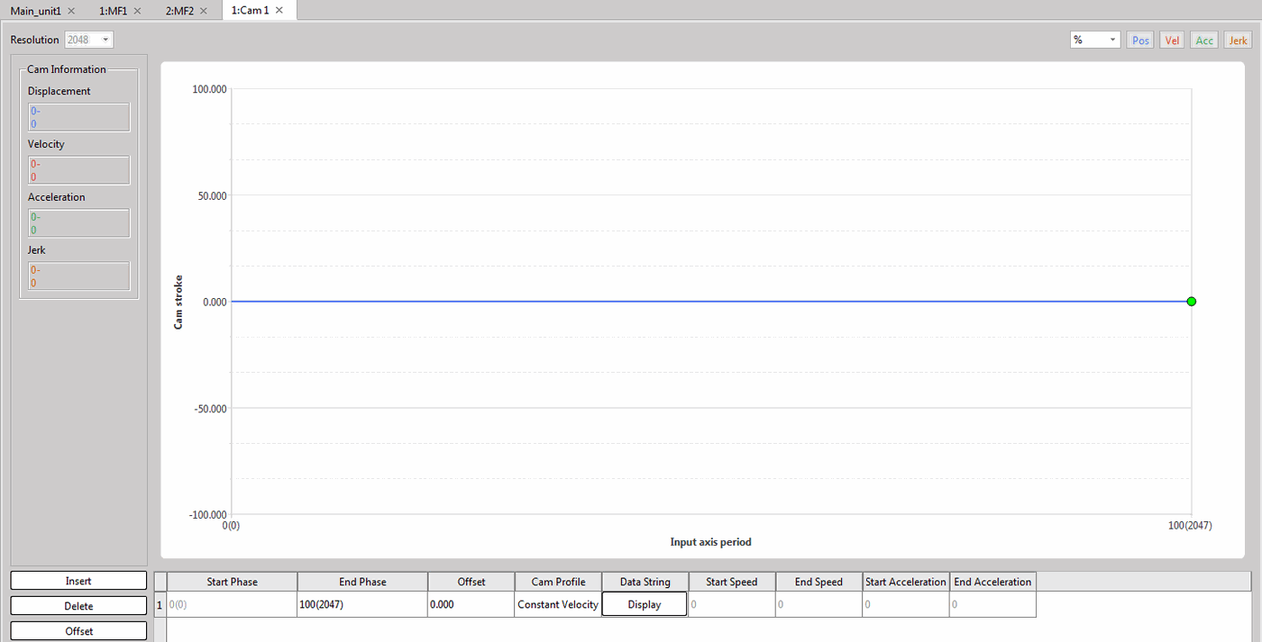
Fig. 202: New Cam setting
Delete Cam setting
Click the scroll-down menu of [Motion Sync Control]. Here, you will be allowed to select [Delete Cam Setting] or you may select [Project] → [Motion Sync Control] → [Cam Setting] in project management window. Next, click the right mouse button to open the scroll-down menu and then select [Delete Cam Setting].
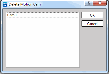
Fig. 203: Delete Cam setting
After being selected, such page will show “Delete Motion Cam” window. Select the cam to be deleted and then press [OK] to delete such cam.
Cam Resolution
Click the scroll-down menu of [Motion Sync Control]. Here, you will be allowed to select [Cam Resolution] or you may select [Project] → [Motion Sync Control] → [Cam Setting] in project management window. Next, click the right mouse button to open the scroll-down menu and then select [Cam Resolution].
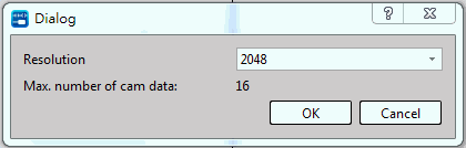
Fig. 204: Cam resolution setting
After being selected, such page will show “Dialog” window. Setting up cam resolution will affect the maximum quantity of the cam that can be added.
9-6 Motion Param Mapping
Click [Project] → [Motion] → [Motion Param Mapping] in function toolbar. You may also select [Project] → [Motion] → [Motion Param Mapping] in project management window and then double clicking the pagination function of [Motion Param Mapping].
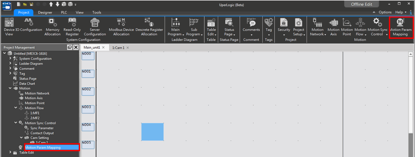
Fig. 205: Motion Param Mapping setting
|
Function |
Description |
|
Add |
Add a new Motion Parameter Table and execute the required setting. |
|
Delete |
Delete old Motion Parameter Table |
|
Up/Down |
Change the sequential address of Motion Parameter Table in Summary Table. |
Regarding the setting details of Motion Parameter Table, please refer to Motion Control User Manual.
9-7 Motion Recipe
Click [Project] → [Motion] → [Motion Recipe] in function toolbar. You may also select [Project] → [Motion] → [Motion Recipe] in project management window and then double clicking the pagination function of [Motion Recipe].
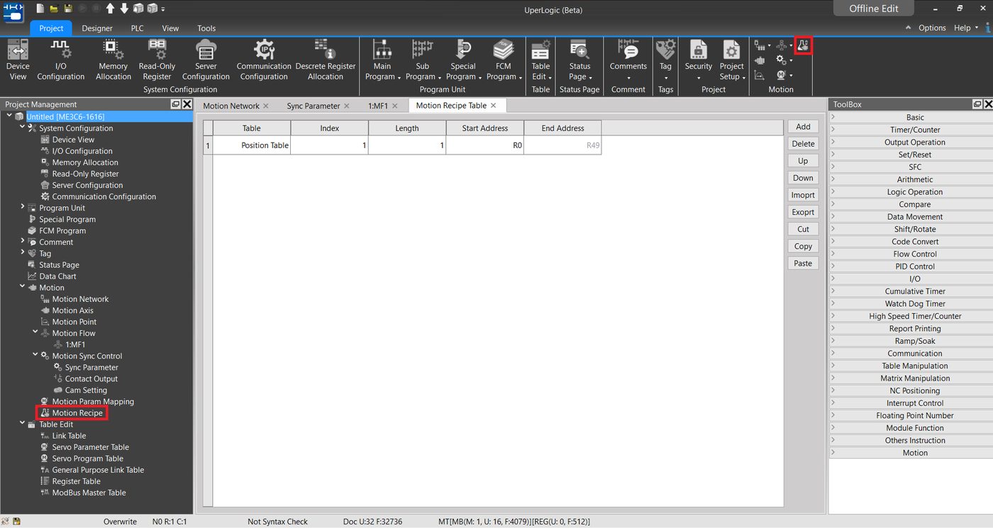
Fig. 206: Motion Recipe setting
|
Function |
Description |
|
Add |
Add a new Motion Recipe and execute the required setting. |
|
Delete |
Delete old Motion Recipe |
|
Up/Down |
Change the sequential address of Motion Parameter Table in Summary Table. |
|
Import/Export |
Export or import information from Motion Recipe |
|
Cut |
Cut out the selected Motion Recipe information |
|
Copy |
Copy selected Motion Recipe information |
|
Paste |
Paste the copied or cut Motion Recipe information at the specified location |
Regarding the setting details of Motion Recipe, please refer to Motion Control User Manual.
Tip: press ← → to switch chapters, Ctrl+K to search