|
⚠Danger |
|
This section describes the auxiliary functions provided by the software for users to check and calculate the corresponding functions more easily.
14-1 System Backup and Restore
This section describes how to execute the Register content backup function and the Register content backup saving function.
14-1-1 System Backup
This function can quickly backup PLC parameters, programs and data to files. Combined with the system restore function, it can be used as an error-prone PLC copy application. The extension of the system backup file is *.fsbx.
The backup process is as follows:
- When operated under “Offline Edit” status, click [Tool] → [System Backup] in function toolbar, as below:
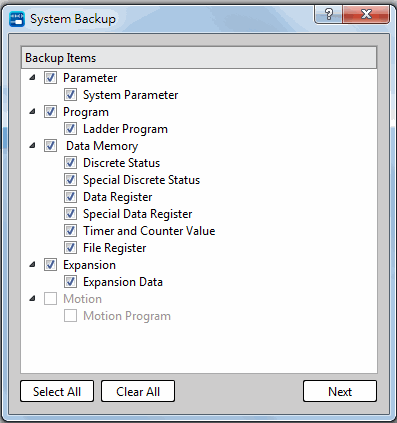
Fig. 278: System backup
|
Function |
Description |
|
|
Parameter |
System Parameter |
PLC current connection parameter setting |
|
Program |
All Program Units |
PLC current complete program data |
|
Data Memory |
Discrete Status |
PLC current input contact (X), output relay (Y), internal relay (M) and step relay (S) values |
|
Special Discrete Status |
PLC current special relay (M) value |
|
|
Data Register |
PLC current data register (R、D) values |
|
|
Special Data Register |
PLC current input register (R), output register (R), special register (R) values |
|
|
Timer and Counter Value |
PLC current timer (T) and counter (C) values |
|
|
File Register |
PLC current file register (F) value |
|
|
Expansion |
Expansion Data |
PLC current expansion module setting data |
|
Motion |
Motion Program |
PLC current motion data |
- If password should be created for such project, then it allows the user to select the intended protection method and add the required password.
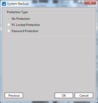
Fig. 279: System backup setting
|
Function |
Description |
|
No Protection |
When restoring such backup file, it is not required to input the password and such file will be restored directly. |
|
PC Locked Protection |
When using this backup file to restore, it can be restored directly but only on the currently operating PC, and cannot be restored on another PC. Typically used in factory production situations. |
|
Password Protection |
To restore such backup file, the user needs to input the password in order to restore the backup file. |
- Users can enter the file name and file comment in the save dialog box, and start the backup after confirmation.
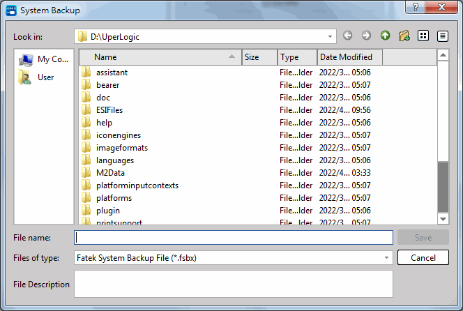
Fig. 280: Saving System backup
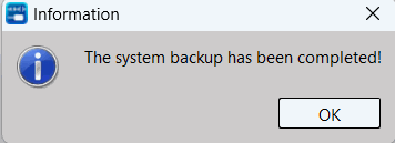
- After the progress window ends, it will prompt that the system backup is complete.
14-1-2 System Backup
This function can quickly write the system restore file ( *.fsbx ) data to the PLC.
The backup process is as follows:
- When operated under “Offline Edit” status, click [Tool] → [System Restore] in function toolbar to select the file to restore, as below:
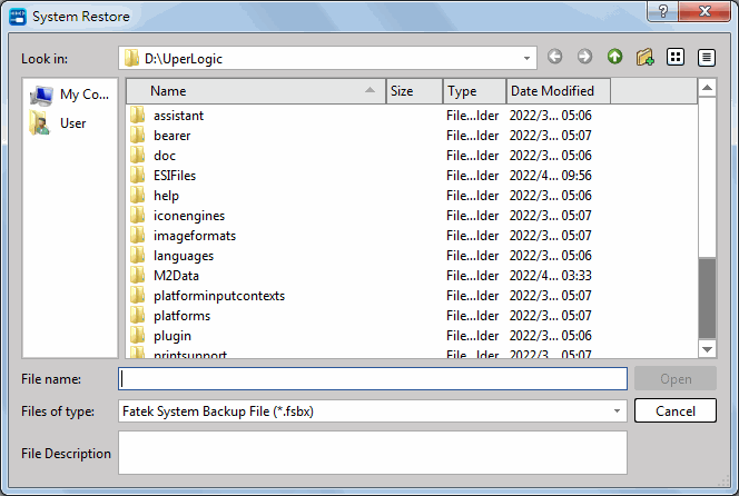
Fig. 281: System restore
- If the file is protected by a password, a password confirmation dialog box will appear at this time, and the restoration will start after the correct input.
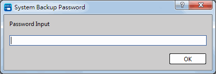
Fig. 282: Input system restoration password
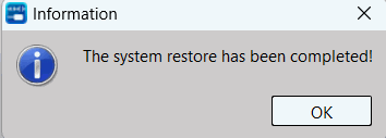
- After the progress window ends, it will prompt that the system restore is complete.
14-2 Memory Card Operations
Click [Tool] → [Memory Card Operations] in function toolbar to show the following window, as below:
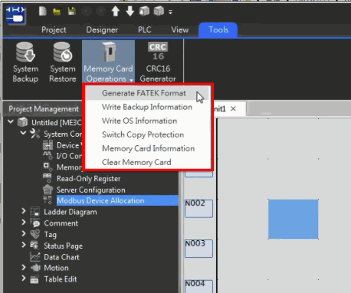
Fig. 283: Memory Card Operations
14-2-1 Write Backup Information
Click [Write Backup Information] and you will see the following screen. Users can perform functions related to memory card backup.
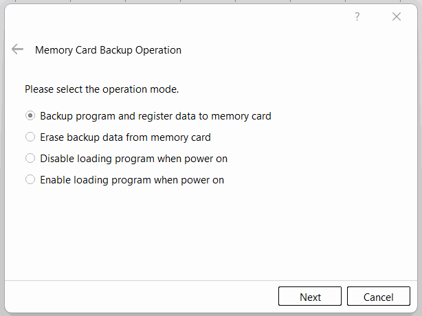
Fig. 284: Memory card backup operation
|
Function |
Description |
|
Backup Program and Register to Memory Card |
This function can replicate the program and register contents to the memory card. After pressing [Next], there will be detailed settings that can be adjusted. For detailed functions, please refer to the Application manual. |
|
Clear Backup Data in Memory Card |
This function can clear the program or data stored in the memory card, click [Next] to start the action. |
|
Enter Trial Mode |
This function allows the user to choose whether to enter the trial modification mode (that is, whether to let the program and data in the memory card overwrite the program and data in the host). Press [Next] to start the action. |
|
Enter Normal Mode |
This functoin allows users to choose whether to enter normal mode. Press [Next] to start the action. |
14-2-2 Write OS Information
Click [Write OS Information] and you will see the following screen. The user can choose to write the update or rescue file of the host or the expansion module. After the import is completed, the corresponding version will be displayed on the OS information side. Please refer to the Application manual for the detailed functions of the OS update and rescue functions of the memory card.
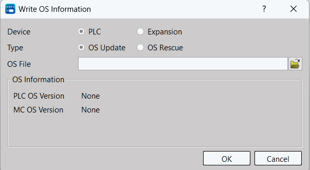
Fig. 285: Write OS Information
|
Item |
Description |
|
Device |
Select the OS written to the [PC] or [Expansion] device. |
|
Type |
Choose to write the OS for [Update] or [Rescue]. |
|
OS Info |
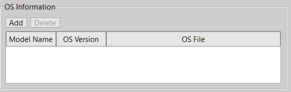
Displays the OS version. When the user chooses to write “OS Update” in “Expansion”, the OS information can be written to multiple firmwares at the same time, as shown in the figure below:
|
|
OS File |
Select the path of the OS file to be written. When the user chooses to write “OS Update” in “Expanded”, this path exists in the OS information. |
14-2-3 Switch Copy Protection
After clicking [Switch Copy Protection], the user can set whether to enable the copy protection of the memory card. After copy protection is enabled, the memory card will be bound to the PC, and the memory card data cannot be transferred to aother PC for use.
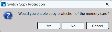
Fig. 286: Copy Protection
14-2-4 Memory Card Information
Click [Memory Card Information] and you will see the following screen. Users can check the relevant information of the memory card through the memory card information.
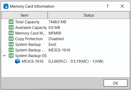
Fig. 287: Memory Card Information
|
Item |
Description |
|
Capacity |
Indicates the full capacity of the memory card. |
|
Available Capacity |
Indicates the available capacity of the memory card. |
|
Memory Card Type |
Indicates the type of the memory card. |
|
Copy Proyection |
Indicates whether to enable copy protection. |
|
System Backup |
Indicates whether there is write backup information. |
|
System Backup Type |
Indicates the model of the write backup. |
|
System Backup Version |
Indicates the firmware and hardware version of the backup. |
|
PC OS Update/Rescue Version |
Indicates the PC update/rescue firmware and hardware version written. |
|
Expansoin OS Update/Rescue Version |
Indicates the Expansionsion update/rescue firmware and hardware version written. |
14-2-5 Clear Memory Card
Click [Clear Memory Card] and you will see the following screen. The user can select the items to be cleared:
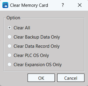
Fig. 288: Clear Memory Card
|
Function |
Description |
|
Clear All |
Clear all data on the memory card. |
|
Clear Backup Data |
Clear the data backed up in Section 14-2-1. |
|
Clear Information Register |
Clear the data register backed up in Section 14-2-1 |
|
Clear PLC OS File |
Clear the PLC OS files written in Section 14-2-2 |
|
Clear Expansoin OS File |
Clear the Expansion OS files written in Section 14-2-2 |
14-3 CRC16 Calculator
The CRC value is generally used to check Communication Protocols. This function allows the system to automatically calculate and generate or inspect the check values after the user enters the data content, which is convenient for planning the packet content when communicating with third-party devices.
Click [Tool] → [CRC16 Calculator] in function toolbar to show the following window, as below:
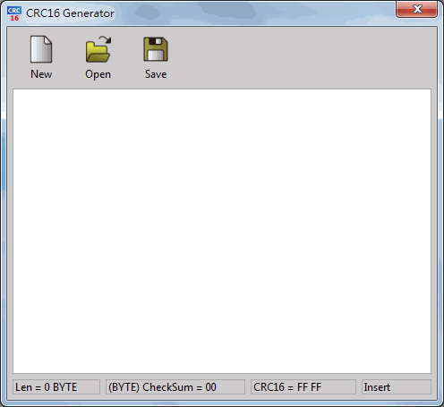
Fig. 289: CRC16 Calculator
After inputting the code to be checked, such function will display the number of bytes (Len) being imported until now and then it will calculate the Checksum value and the CRC16 value automatically. After completing the input, press [Save] for saving as the sub-file named as “txt” text file. In this way, it allows the user to call out the text file by pressing [Open] during the next round of operation without the need of executing input steps once again. Press [New], the input field will be cleared as blank ready for inputting again. Clicking the upper-right [X] icon or [Close], the user will be allowed to close the CRC16 Calculator window.
Appendix 1_Quick Start
This section will guide the user to quickly create the intended project and download it to PLC to run.
- First, download the UperLogic from the website and then start the installation. For detailed installation steps, please refer to Chapter 2.
- Click [UperLogic] to open new project. Next, click [Project] → [Project] → [Options] → [File] in function toolbar and then execute the project backup setting so as to prevent the designed project from losing inadvertently.
Regarding detailed file setting steps, please refer to Chapter 4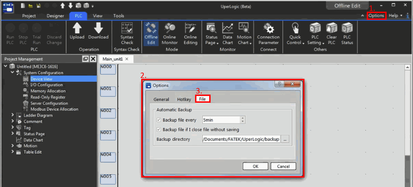
Fig. 290: Setting backup project
- Open a new Project.
- Click [Designer] → [Ladder Diagram] in function toolbar to create an easy-to-use project.
For detailed information of Ladder Diagram, please refer to Chapter 6.
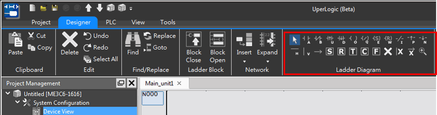
Fig. 291: Creating easy-to-use project
- After creating the desired project, click [PLC] → [Connection Parameter] in function toolbar to establish the online communication with the PLC. In this example, the online will be established through USB/Type C. Therefore, the user needs to confirm that the PLC is properly connected with the PC with the USB/Type C cable and then check if the communication is correctly established through the online test.
For detailed information of online parameter, please refer to Chapter 11.
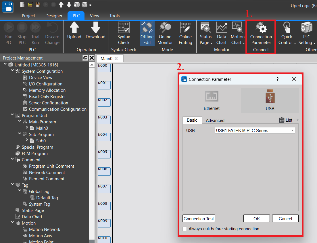
Fig. 290: Creating connection
- After creating the desired connection parameter, click [PLC] → [Operation] → [Download] in function toolbar to download the project to the PLC. Before starting the download procedure, the software will compare the project with the PLC and then tell the user about the difference between both for the user to select the desired download item.
For detailed information of downloading, please refer to Chapter 11.
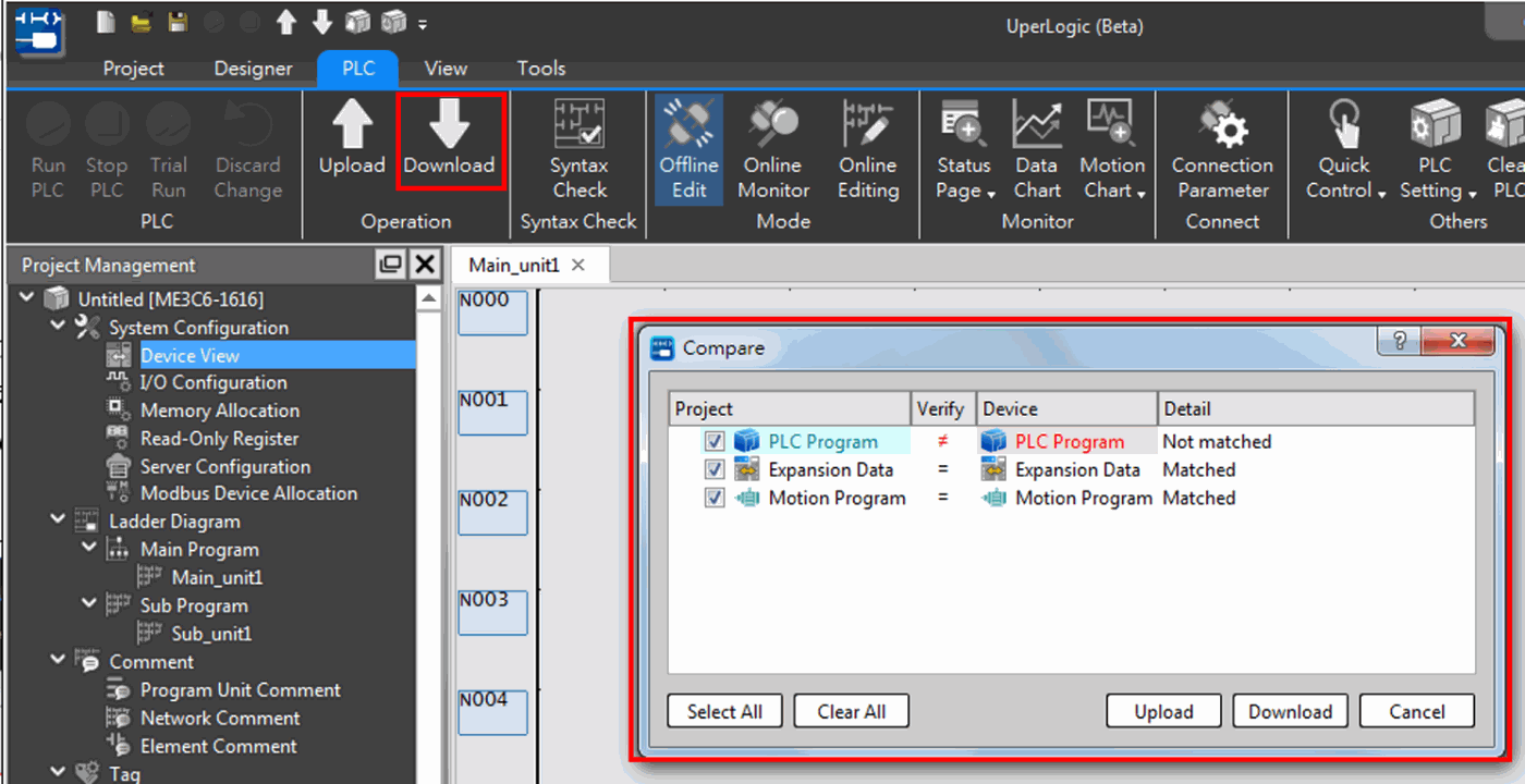
Fig. 291: Downloading project to PLC
- After completing the download process, click [PLC] → [Mode] → [Online Monitor] in function toolbar and you will be allowed to monitor the PLC program operating status. When accessing the [Online Monitor], the system will display the window showing present PLC status for reference by the user. For detailed information of monitoring, please refer to Chapter 12.
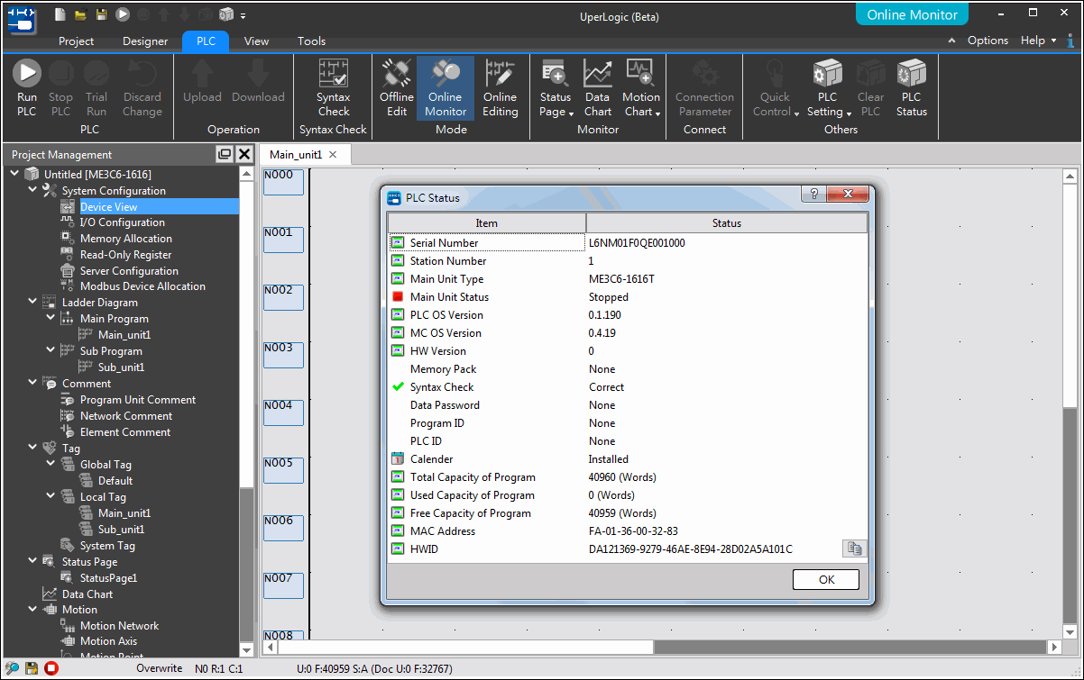
Fig. 292: Online monitoring PLC
- After finishing the “Online Monitor” mode, the user may click the upper-left “File”
 → “Save Project” to finish the online monitoring.
For detailed project saving steps, please refer to Chapter 4.
- Now, you have completed the editing of the easy-to-use project.
Tip: press ← → to switch chapters, Ctrl+K to search