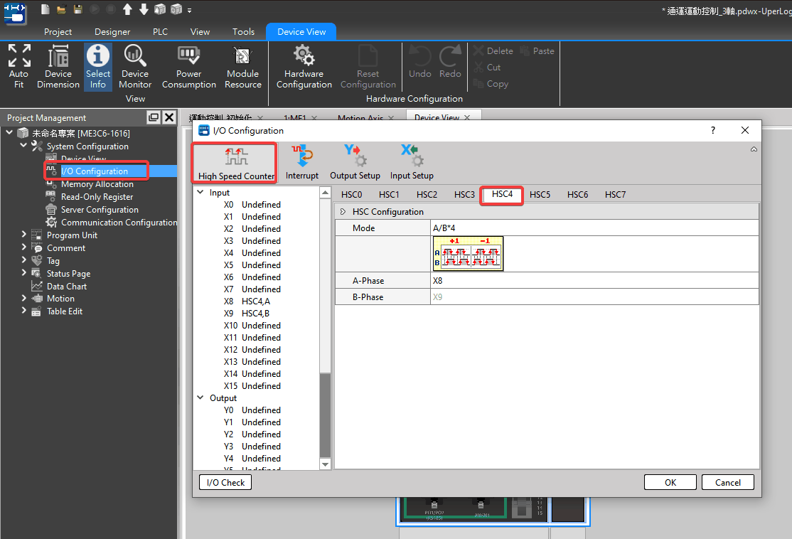
The hand wheel is mainly used to control the pulse number of the input axis. When using the hand wheel function, the user must first set the EtherCAT hand wheel input points X0-X15 to high-speed counting HSC0~HSC7.
Users can find the settings in [I/O Configuration] > [High Speed Counter] > HSC0 – HSC7.
The HSC4~7 are located on motion controller and only support A/B*4 mode, and A/B*4 will amplify the output pulse number by 4 times.
HSC0 = External Reference Number 1, HSC2 = External Reference Number 2, etc. The synchronization parameters will be used later.
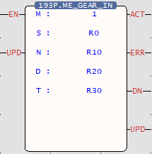
Fun193.MFGearMPG
Parameter Description
Ladder Symbol
EN = 1
Output Control
UPD = 1
Updating Parameter
ACT = 1
Acting
ERR = 1
Error
DN = 1
Output is done
UPD =1
Update is done
Internal Prameter
Input Source of M Master Axis
EtherCAT_Axis No. 1-16
Encoder_Gray Code 100
(X8-X15)
Encoder_Hardware High-Speed Counter No. 101-108
( HSC0~HSC7 )
Ouput Target of S Slave Axis
EtherCAT_Axis No. 1-16 ([Input Source of M Master Axis] cannot be same as [Ouput Target of S Slave Axis])
N Variable Gear Ratio Numerator
Positive and negative numbers, including [Decimal Point Position] in [Motion Axis Setting] in [Motion Control].
D Variable Gear Ratio Denominator
Positive number (a real number greater than zero), including the [Decimal Point Position] of the [Motion Axis Setting] in [Motion Control].
T Transition Time (ms)
Positive number (a real number greater than zero), unit: ms
Example
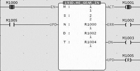
Ladder
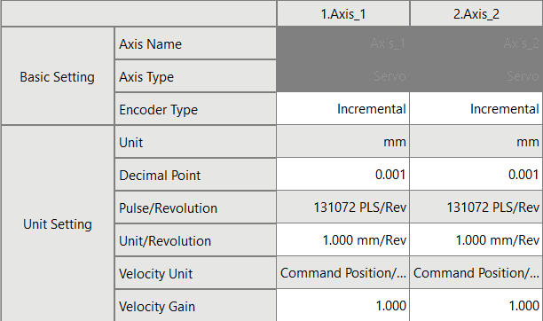
Axis Parameter Setting
When M1000 is from OFF→ON, it will follow the current Fun193 parameter
(M: EtherCAT axis 1, N: EtherCAT axis 2, N: variable gear ratio numerator 0.001, D variable gear ratio denominator 0.001, T: 1ms) to start hand wheel synchronization.
When EtherCAT axis 1 moves by 100 mm, EtherCAT axis 2 moves by 100 mm.
Was this page helpful?
Thanks for your feedback!
Tip: press ←→ to switch chapters, Ctrl+K to search