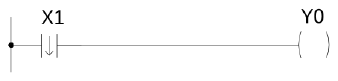
The total number of timers is 1024 (T0~T1023) with three different time bases, 0.01S, 0.1S and 1S.The default number and allocation of timers is shown as below (Can be adjusted according to user’s actual requirements by the “Configuration” function):
T0~T255:0.001S timer(default as 0.00~32.767S)
T256~T511:0.01S timer(default as 0.0~327.67S)
T512~T767:0.1S timer(default as 0~3276.7S)
T768~T1023:1S timer(default as 0~32767S)
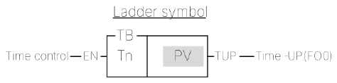
The Timer of M-Series PLC will start to run when subprogram triggers. To stop the Timer operation, you must Disable the Timer, not calling the subprogram, which is not equal to Disable Timer. If there is no Disable Timer, it will continue to count.
T
TIMER
T
If PV is a register, then Timer’s time = Time base x register content. Therefore, you only need to change the register content to change the timer’s time. Please refer to Example 2.
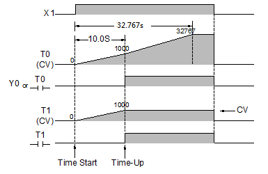
The maximum error of a timer is a time base plus a scan time. In order to reduce the timing error in the application, please use the timer with a smaller time base.
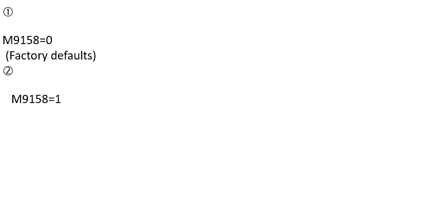
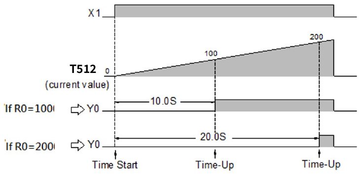
When the time control “EN” is 1, the timer will start timing (the current value will accumulate from 0) until “Time Up” (i.e., CV≧PV), then the Tn contact and TUP (FO0) will change to 1. As long as the timer control “EN” input is kept as 1, even the CV of Tn has reached or exceeded the PV, the CV of the timer will continue accumulating, until it reaches the maximum limit (32767). The Tn contact status and flag will remain as 1 when CV≧PV, unless the “EN” input is 0. When “EN” input is 0, the CV of Tn will be reset to 0 immediately and the Tn contact and “Time Up” flag TUP will also change to 0 (please refer to the diagram ➀ below).
T
TIMER
T
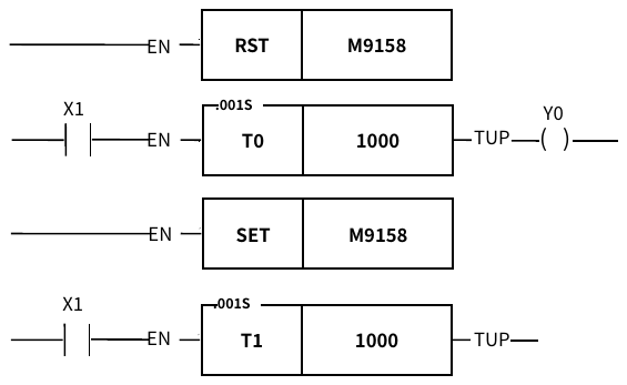
Example 1
Fixed Time Timer
Ladder diagram
ST
M9158 := FALSE;
Timer( EN:= X1,
T:= 0,
PV:= 1000,
IsTimeout=> Y0);
M9158 := TRUE;
Timer( EN:= X1,
T:= 1,
PV:= 1000,
IsTimeout=> T1);
T
TIMER
T
Example 2
Variable Time Timer
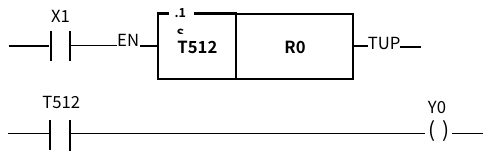
The preset value (PV) shown in example 1 is a constant which is equal to 1000. This value is fixed and can not be changed once programmed. In many circumstances, the preset time of the timers needs to be varied while PLC running. In order to change the preset time of a timer, can first use a register as the PV operand (R or D…) and then the preset time can be varied by changing the register content. As shown in this example, if set R0 to 100, then T becomes a 10S Timer, and hence if set R0 to 200, then T becomes a 20S Timer. So that we can easily change the timer dynamically while the PLC is running.
Ladder diagram
ST
Timer( EN:= X1,
T:= 512,
PV:= R0,
IsTimeout=> T512);
IF T512 THEN
Y0 := TRUE;
ELSE
Y0 := FALSE;
END_IF
An example of applying the “time-up” status by using the T512 contact.
Note: If the preset value of the timer is equal to 0, then the timer’s contact status and become 1 ("EN" input must be at 1) immediately, after the PLC finishes its first scan because "Time-Up" has occurred. (TUP) stays at 1 until "EN" input changes to 0.
6-2 COUNTER(C)
C
COUNTER
(16-Bit: C0~C1023,32-Bit: C1024~C1279)
C
Symbol
Operand
Cn: The Counter number
PV: Preset value
Range
Operand
WX
WY
WM
WSM
WS
TMR
CTR
HR
IR
OR
SR
ROR
DR
DR
K
WX0
∣
WX1008
WY0
∣
WY1008
WM0
∣
WM9104
WM9120
∣
WM25584
WS0
∣
WS3088
T0
∣
T1023
C0
∣
C1279
R0
∣
R34767
R34768
∣
R34895
R35024
∣
R35151
R35280
∣
R43223
R43224
∣
R47319
D0
∣
D7999
D0
∣
D11999
0
∣
32767
Cn
○
○
○
PV
○
○
○
○
○
○
○
○
○
○
○
○
○
○
Description
There is total 1024 16-Bit counters (C0~C1023). The range of preset value is between 0~32767. C0~C139 are Retentive Counters and the CV value will be retained when the PLC turns on or RUN again after a power failure or a PLC STOP. C140~C1023 are Non-Retentive Counters, if a power failure or PLC STOP occurs, the CV value will be reset to 0 when the PLC turns on or RUN again.
There is total 56 32-Bit counters (C1024~C1079). The range of the preset value is between 0~2147483647. C1024~C1063 are Retentive Counters and C1063~C1279 are Non-Retentive Counters.
The above 16-bit and 32-bit counters’ retentive/non-retentive number distribution is the original factory setting. If this does not meet your needs, you can use the "Frame Configuration" function to adjust.
To ensure the proper counting from C0~C1024, the sustain time of input status of CLK should greater than 1 scan time.
This command counts based on the changes in the PLS signal during each scan cycle. Therefore, as long as the duration of the signal change exceeds the scan cycle, this command can detect the change. However, the scan cycle time will vary depending on the number of user programs. To obtain accurate count values, please use a high-speed counter in software or hardware.
C
COUNTER
(16-Bit: C0~C1023,32-Bit: C1024~C1279)
C
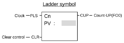
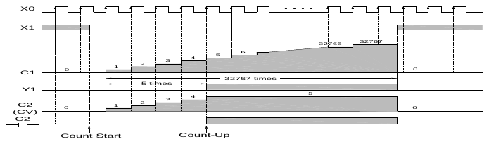
When "CLR" is at 1, all of the contact Cn, FO0 (CUP), and CV value of the counter CV are cleared to 0 and the counter stops counting.
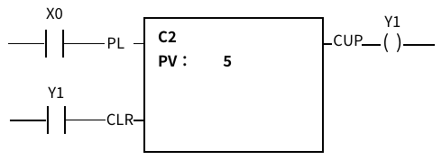
When "CLR" = 0, the counter is allowed to count, because the counter command is essentially a "P command", so only when the counting pulse "PLS" changes from 0 to 1, the current value CV of the counter Cn will increase by 1. Until "Count up" (Count up, that is, CV value ≧ set value), the count up contact Cn and the count up flag CUP (FO0) of the counter will both become 1. If there is still counting pulse input at this time, the current value CV of Cn will exceed the set value and continue to accumulate, until it reaches the upper limit (32767 or 2147483647), and the Cn contact and the counting flag CUP will As long as CV≧PV, it will always be 1, unless the clear control CLR input becomes 1. (Please refer the diagram ➀ below)
Example 1
Fixed Time Counter
Ladder diagram
ST
Counter( Pulse:= X0,
Clr:= Y1,
C:= 2,
PV:= 5,
IsUp=> Y1);
C
COUNTER
(16-Bit: C0~C1023,32-Bit: C1024~C1279)
C
Example 2
32-Bit counter with variable value
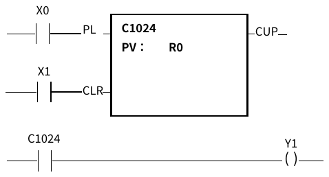
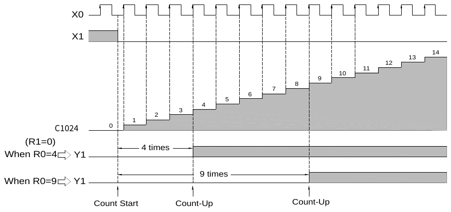
Like a timer, if the PV of a counter is changed to a register (such as R, D, and so on), the counter will use the register contents as the counting PV. Therefore, only need to change the register contents to change the PV of the counter while PLC is running. Below is an example of a 32-bit counter that uses the data register R0 as the PV (in fact it is the 32-bit PV formed by R1 and R0).
Like a timer, if the PV of a counter is changed to a register (such as R, D, and so on), the counter will use the register contents as the counting PV. Therefore, only need to change the register contents to change the PV of the counter while PLC is running. Below is an example of a 32-bit counter that uses the data register R0 as the PV (in fact it is the 32-bit PV formed by R1 and R0).
Ladder diagram
ST
Counter( Pulse:= X0,
Clr:= X1,
C:= 1024,
PV:= R0,
IsUp=> C1024);
IF C1024 THEN
Y1 := TRUE;
ELSE
Y1 := FALSE;
END_IF
An example of applying the “Time-up” status by using the C1024 contact.
C
COUNTER
(16-Bit: C0~C1023,32-Bit: C1024~C1279)
C
Example 2
32-Bit counter with variable value
➀
➁
Note: If the preset value of the counter is 0 and "CLR" input also at 0, then the Cn contact status and FO0 (CUP) becomes 1 immediately after the PLC finishes its first scan because the "Count-Up" has occurred. It will stay at 1 regardless how the CV value varies until "CLR" input changes to 1.
6-3 SET(S)
SET D P
SET
(Set coil or all the bits of register to 1)
SET D P
Symbol
Operand
D: destination to be set
(The number of a coil or a register)
Range
Operand
Y
M
SM
S
WY
WM
WSM
WS
TMR
CTR
HR
IR
OR
SR
ROR
DR
Y0
∣
Y1023
M0
∣
M9119
M9120
∣
M25599
S0
∣
S3103
WY0
∣
WY1008
WM0
∣
WM9104
WM9120
∣
WM25584
WS0
∣
WS3088
T0
∣
T1023
C0
∣
C1279
R0
∣
R34767
R34768
∣
R34895
R35024
∣
R35151
R35280
∣
R43223
R43224
∣
R47319
D0
∣
D7999
D
○
○
○*
○
○
○
○
○
○
○
○
○
○
○*
○*
○
Description
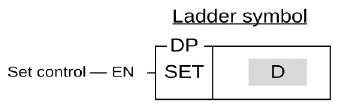
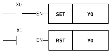
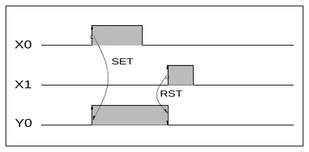
When the set control "EN" =1 or from 0 → 1 (P instruction), sets the bit of a coil or all bits of a register to 1.
Example 1
Single Coil Set
Ladder diagram
ST
IF X0 THEN
Y0 := TRUE;
END_IF
IF X1 THEN
Y0 := FALSE;
END_IF
SET D P
SET
(Set coil or all the bits of register to 1)
SET D P
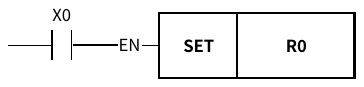
Example 2
Set 16-Bit Register
Ladder diagram
ST
IF X0 THEN
R0 := -1;
END_IF
B15 B0
↓ ↓
D
R0
1
0
1
1
0
1
1
0
1
1
1
0
1
1
0
0
⇩X0=
B15 B0
↓ ↓
D
R0
1
1
1
1
1
1
1
1
1
1
1
1
1
1
1
1
SET D P
SET
(Set coil or all the bits of register to 1)
SET D P
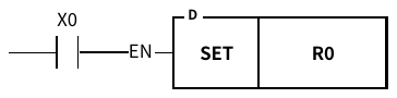
Example 3
32-Bit Register Set
Ladder diagram
ST
IF X0 THEN
DR0 := -1;
END_IF
B31 R1 R0 B0
↓ ∣ ↓
D
R0
1
0
1
1
0
1
1
0
1
0
1
1
1
0
1
1
1
1
1
1
0
1
0
1
1
0
1
1
0
0
0
1
⇩X0=1
D
R0
1
1
1
1
1
1
1
1
1
1
1
1
1
1
1
1
1
1
1
1
1
1
1
1
1
1
1
1
1
1
1
1
Note: If you use a single coil set (Y, M, S), it is recommended to use "coil set", the efficiency of using the PLC will be better than set instruction
The example is as follows:
6-4 RST(R)
RST D P
RESET
(Reset the coil or the register to 0)
RST D P
Symbol
Operand
D: Destination to be reset
(The number of a coil or a register)
Range
Operand
Y
M
SM
S
WY
WM
WSM
WS
TMR
CTR
HR
OR
SR
ROR
DR
Y0
∣
Y1023
M0
∣
M9119
M9120
∣
M25599
S0
∣
S3103
WY0
∣
WY1008
WM0
∣
WM9104
WM9120
∣
WM25584
WS0
∣
WS3088
T0
∣
T1023
C0
∣
C1279
R0
∣
R34767
R35024
∣
R35151
R35280
∣
R43223
R43224
∣
R47319
D0
∣
D7999
D
○
○
○*
○
○
○
○
○
○
○
○
○
○*
○*
○
Description
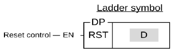
When the reset control "EN" =1 or from 0 → 1 ( P instruction ), resets the coil or register to 0.
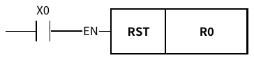
Example 1
Single Coil Reset
Please refer to example 1 for the SET instruction
Example 2
16-Bit Register Reset
Ladder diagram
ST
IF X0 THEN
R0 := 0;
END_IF
B15 B0
↓ ↓
D
R0
1
1
0
1
1
1
1
0
1
1
1
1
1
1
1
0
⇩X0=
B15 B0
↓ ↓
D
R0
0
0
0
0
0
0
0
0
0
0
0
0
0
0
0
0
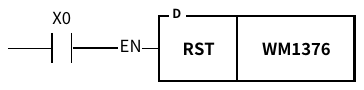
Example 3
32-Bit Register Reset
Ladder diagram
ST
IF X0 THEN
WM1376 := 0;
END_IF
M1408 WM1392 WM1376 M1376
↓ ∣ ↓
D
WM1376
0
1
1
0
1
1
1
0
0
0
0
0
1
1
0
1
1
1
0
1
1
1
0
1
1
1
0
1
1
1
0
1
⇩X0=1
D
WM1376
0
0
0
0
0
0
0
0
0
0
0
0
0
0
0
0
0
0
0
0
0
0
0
0
0
0
0
0
0
0
0
0
Note:
If you use a single coil reset (Y, M, S), it is recommended to use "coil reset", the efficiency of using the PLC will be better than set instruction
The example is as follows:
6-5 MASTER CONTROL(MC)
FUN0
MC
MASTER CONTROL LOOP START
FUN0
MC
Symbol
Operand
N: Master Control Loop number (N=0~127) the number N cannot be used repeatedly.
Description
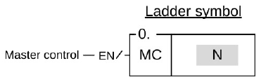
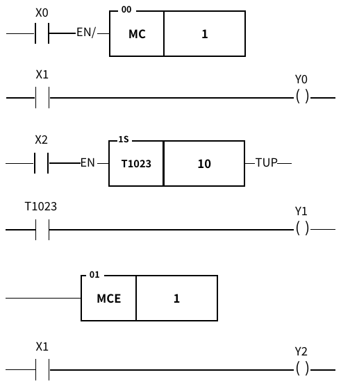
M There are a total of 128 MC loops (N=0~127). Every Master Control Start instruction, MC N, must correspond to a Master Control End instruction, MCE N, which has the same loop number as MC N. They must always be used in pairs and you should also make sure that the MCE N instruction is after the MC N instruction.
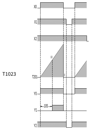
When the Master Control input "EN/" is 1, then this MC N instruction will not be executed, as it does not exist.
When the Master Control input "EN/" is 0, the master control loop is active, the area between the MC N and MCE N is called the Master Control active loop area. All the status of OUT coils or Timers within Master Control active loop area will be cleared to 0. Other instructions will not be executed.
FUN0
MC
MASTER CONTROL LOOP START
FUN0
MC
Ladder diagram
ST
IF M0 = FALSE THEN
IF M1 THEN Y0 := TRUE;
ELSE
Y0 := FALSE;
END_IF
Timer( EN:= M2,
T:= 1023,
PV:= 10,
IsTimeout=> T1023);
IF T1023 THEN Y1 := TRUE;
ELSE
Y1 := FALSE;
END_IF
ELSE
IF M1 THEN Y2 := TRUE;
ELSE
Y2 := FALSE;
END_IF
END_IF
FUN0
MC
MASTER CONTROL LOOP START
FUN0
MC
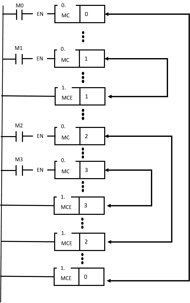
Note 1: MC/MCE instructions can be used in nesting or interleaving as shown to the right:
6-6 MASTER CONTROL END(MCE)
FUN1
MCE
MASTER CONTROL LOOP END
FUN1
MCE
Symbol
Operand
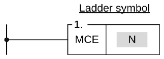
N: Master Control End number (N=0~127) N can not be used repeatedly.
Description
Every MCE N must correspond to a Master Control Start instruction. They must always be used as a pair and you should also make sure that the MCE N instruction is after the MC N instruction. After the MC N instruction has been executed, all output coil status and timers will be cleared to 0 and no other instructions will be executed. The program execution will resume until a MCE instruction which has the same N number as MC N instruction appears.
MCE instruction does not require an input control because the instruction itself forms a network which other instructions can not connect to it. If the MC instruction has been executed then the master control operation will be completed when the execution of the program reaches the MCE instruction. If MC N instruction has never been executed then the MCE instruction will do nothing.
Example 1
Please refer to the example and explanations for MC instruction.
6-7 SKIP(SKP)
FUN2
SKP
SKIP START
FUN2
SKP
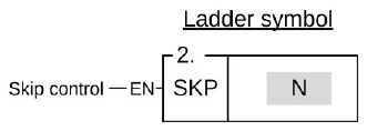
Symbol
Operand
N: Skip loop number (N=0~127),
N can not be used repeatedly.
Description
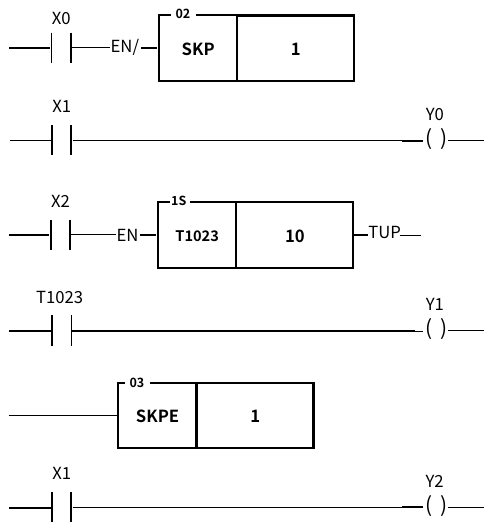
There is total 128 SKP loops (N=0~127). Every skip start instruction, SKP N, must correspond to a skip end instruction, SKPE N, which has the same loop number as SKP N. They must always be used as a pair and you should also make sure that the SKPE N instruction is after the SKP N instruction.
When the skip control "EN" is 0, then the Skip Start instruction will not be executed (An equivalent SKP N command does not exist).
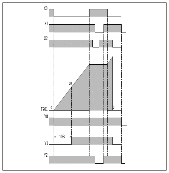
When the skip control "EN" is 1, the range between the SKP N and SKPE N which is so called the Skip active loop area will be skipped, that is all the instructions in this area will not be executed. Therefore, the statuses of the discrete or registers in this Skip active loop area will be retained.
FUN2
SKP
SKIP START
FUN2
SKP
Example
Ladder diagram
ST
6-8 SKIP END(SKPE)
FUN3
SKPE
SKIP END
FUN3
SKPE
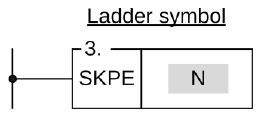
Symbol
Operand
N: SKIP END Loop number (N=0~127) N can not be used repeatedly.
Description
Every SKPE N must correspond to a SKP N instruction. They must always be used as a pair and you should also make sure that the SKPE N instruction is behind the SKP N instruction.
SKPE instruction does not require an input control because the instruction itself forms a network which other instructions can not connect to it. If the SKP N instruction has been executed then the skip operation will be completed when the execution of the program reaches the SKPE N instruction. If SKP N instruction has never been executed then the SKPE instruction will do nothing.
Example 1
Please refer to the example and explanations for SKP N instruction.
6-9 DIFFERENTIAL UP (DIFU)
FUN4 P
DIFU
DIFFERENTIAL UP
FUN4 P
DIFU
Symbol
Operand
D: The specific coil number where the result of the Differential Up operation is stored.
Range
Operand
Y
M
SM
S
Y0
∣
Y1023
M0
∣
M9119
M9120
∣
M25599
S0
∣
S3103
D
○
○
○*
○
Description
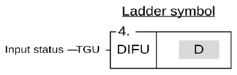
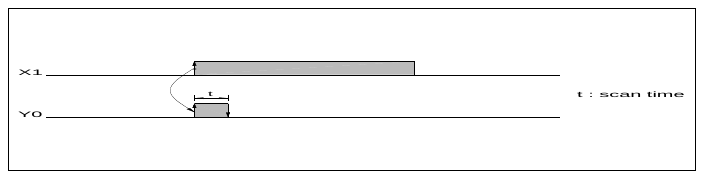
The DIFU instruction is used to output the up differentiation of a node status (status input to "TGU") and the pulse signal resulting from the status change at the rising edge of the "TGU" for one scan time is stored to a coil specified by D.
The functionality of this instruction can also be achieved by using a TU contact.。
FUN4 P
DIFU
DIFFERENTIAL UP
FUN4 P
DIFU
Example
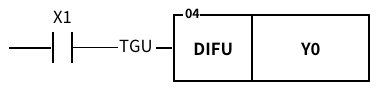
The results of the following two samples are exactly the same
Ladder diagram
ST
Example 1
R_TRIG( S:= X1, D=>Y0 );
Example 2
R_TRIG( S:= X1, D=>Y0 );
6-10 DIFFERENTIAL DOWN(DIFD)
FUN5 P
DIFD
DIFFERENTIAL DOWN
FUN5 P
DIFD
Symbol
Operand
D: The specific coil number where the result of the Differential Up operation is stored.
Range
Operand
Y
M
SM
S
Y0
∣
Y1023
M0
∣
M9119
M9120
∣
M25599
S0
∣
S3103
D
○
○
○*
○
Description
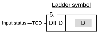
The DIFD instruction is used to output the down differentiation of a node status (status input to "TGD") and the pulse signal resulting from the status change at the falling edge of the "TGD" for one scan time is stored to a coil specified by D.
The functionality of this instruction can also be achieved by using a TD contact.
Example
The results of the following two samples are exactly the same
Ladder Diagram
ST
Example 1
F_TRIG( S:= X1, D=>Y0 );
Example 2
R_TRIG( S:= X1, D=>Y0 );
6-11 BIT SHIFT(BSHF)
FUN6 D P
BSHF
BIT SHIFT
(Shifts the data of the 16-bit or 32-bit register to left or to right by one bit)
FUN6 D P
BSHF
Symbol
Operand
D: The register number for shifting
Range
Operand
WY
WM
WSM
WS
TMR
CTR
HR
OR
SR
ROR
DR
WY0
∣
WY1008
WM0
∣
WM9104
WM9120
∣
WM25584
WS0
∣
WS3088
T0
∣
T1023
C0
∣
C1279
R0
∣
R34767
R35024
∣
R35151
R35280
∣
R43223
R43224
∣
R47319
D0
∣
D7999
D
○
○
○
○
○
○
○
○
○*
○*
○
Description
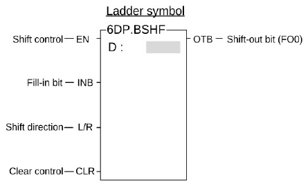
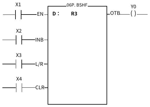
When the status of clear control "CLR" is at 1, then the data of register D and FO0 will all be cleared to 0. All other input signals are invalid.
When the status of clear control is "CLR" at 0, then the shift operation is permissible. When the shift control "EN" = 1 or from 0 →1 (P Instruction), the data of the register will be shifted to right (L/R=0) or to left (L/R=1) by one bit. The shifted-out bit (MSB when shift to left and LSB when shift to right) for both cases will be sent to FO0. The vacated bit space (LSB when shift to left and MSB when shift to right) due to shift operation will be filled in by the input status of fill-in bit "INB".
FUN6 D P
BSHF
BIT SHIFT
(Shifts the data of the 16-bit or 32-bit register to left or to right by one bit)
FUN6 D P
BSHF
Example
Shifts the 16-bit register data
Ladder Diagram
ST
X3=1
(Left shift)
B15
B0
←-
←
←
←
←
←
←
←
←
←
←
←
←
←
←
←
←
←-
Y0
Shifts the 16-bit data to left by one bit
X2
X3=0
(Right shift)
B15
B0
-→
→
→
→
→
→
→
→
→
→
→
→
→
→
→
→
→
-→
X2
Shifts the 16-bit data to right by one bit
Y0
6-12 UP/DOWN COUNTER(UDCTR)
FUN7 D P
UDCTR
UP/DOWN COUNTER
(16-bit or 32-bit up and down 2-phase Counter)
FUN7D P
UDCTR
Symbol
Operand
CV: The number of the Up/Down Counter
PV: Preset value of the counter or it’s register number
Range
Operand
WX
WY
WM
WSM
WS
TMR
CTR
HR
IR
OR
SR
ROR
DR
K
WX0
∣
WX1008
WY0
∣
WY1008
WM0
∣
WM9104
WM9120
∣
WM25584
WS0
∣
WS3088
T0
∣
T1023
C0
∣
C1279
R0
∣
R34767
R34768
∣
R34895
R35024
∣
R35151
R35280
∣
R43223
R43224
∣
R47319
D0
∣
D7999
16/32 – bit’ +/- number
CV
○
○
○
○
○
○
○
○
○
○*
○*
○
PV
○
○
○
○
○
○
○
○
○
○
○
○
○
○
Description
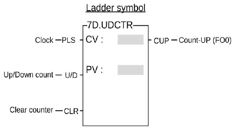
When the clear control “CLR” is 1, the counter’s CV will be reset to 0 and the counter will not be able to count.
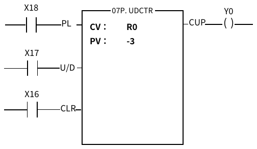
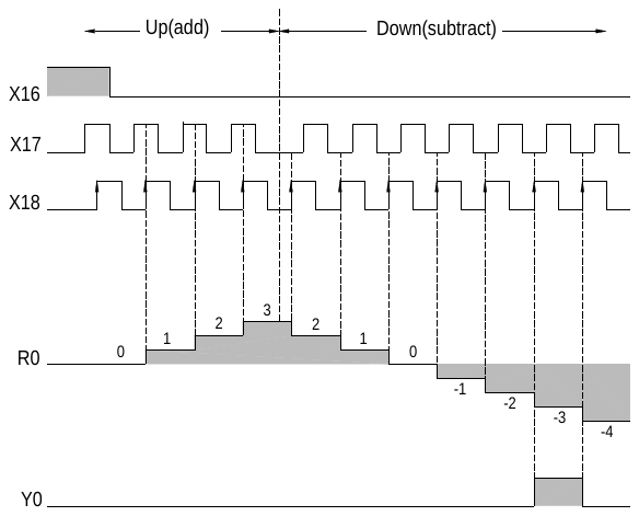
When the clear control “CLR” is 0, counting will then be allowed. The nature of the instruction is a P instruction. Therefore, when the count-pulse “PLS” is from 0→1 (rising edge), the CV will be increased by 1 (if U/D=1) or decreased by 1 (if U/D=0).
When CV=PV, FO0(“Count-Up) will change to 1”. If there are more clocks input, the counter will continue counting which cause CV≠PV. Then, FO0 will immediately change to 0. This means the “Count-Up” signal will only be equal to 1 if CV=PV, or else it will be equal to 0 (Care should be taken to this difference from the “Count-Up” signal of the general counter).
The upper limit of up count value is 32767 (16-bit) or 2147483647 (32-bit). After the upper limit is reached, if another up-count clock is received, the counting value will become –32768 or -2147483648 (the lower limit of down count).
The lower limit of down count value is -32767 (16-bit) or -2147483647 (32-bit). After the lower limit is reached, if another down count clock is received, the counting value will become 32768 or 2147483648 (the upper limit of up count).
If U/D is fixed as 1, the instruction will become a single-phase up count counter. If U/D is fixed as 0, the instruction will become a single-phase down count counter.
Example
Ladder Diagram
ST
Note 1: Since the counting operation of UDCTR is implemented by software scanning, therefore if the clock speed is faster than the scan speed, lose count may then happen (This instruction counts based on the changes in the PLS signal during each scan cycle. Therefore, as long as the duration of the signal change exceeds the scan cycle, this instruction can detect the change. However, the scan cycle time will vary depending on the complexity of the user’s program. To obtain accurate count values, please use a software or hardware high-speed counter. ). Please use the software or hardware high-speed counter in the PLC. Refer to the “High Speed Counter Application” in the Advanced Manual.
Note 2: In order to ensure that this command can count correctly, the width of the counting pulse must be greater than one scan time no matter it is 1 or 0.
6-13 MOVE(MOV)
FUN8 D P
MOV
MOVE
(Moves data from S to D)
FUN8 D P
MOV
Symbol
Operand
S: Source register number
D: Destination register number
The S, D may combine with V, Z, P0~P9 to serve indirect addressing
Range
Operand
WX
WY
WM
WSM
WS
TMR
CTR
HR
IR
OR
SR
ROR
DR
K
XR
WX0
∣
WX1008
WY0
∣
WY1008
WM0
∣
WM9104
WM9120
∣
WM25584
WS0
∣
WS3008
T0
∣
T1023
C0
∣
C1279
R0
∣
R34767
R34768
∣
R34895
R35024
∣
R35151
R35280
∣
R43223
R43224
∣
R47319
D0
∣
D7999
16/32 – bit +/− number
V、Z
P0-P9
S
○
○
○
○
○
○
○
○
○
○
○
○
○
○
○
D
○
○
○
○
○
○
○
○
○
○*
○*
○
○
Description
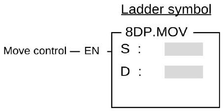
Move (write) the data of S to a specified register D when the move control input "EN" =1 or from 0 to 1 (P Instruction).
FUN8 D P
MOV
MOVE
(Moves data from S to D)
FUN8 D P
MOV
Example
Writes a constant data into a 16-bit register.
Ladder Diagram
ST
IF X0 THEN
R0 := 10;
END_IF
S
K
10
⇩X0=
D
R0
10
6-14 MOVE INVERSE(MOV/)
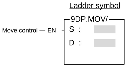
FUN9 D P
MOV/
MOVE INVERSE
(Inverts the data of S and moves the result to a specified device D)
FUN9 D P
MOV/
Symbol
Operand
S: Source register number
D: Destination register number
S, D may combine with V, Z, P0~P9 to serve indirect addressing
Range
Operand
WX
WY
WM
WSM
WS
TMR
CTR
HR
IR
OR
SR
ROR
DR
K
XR
WX0
∣
WX1008
WY0
∣
WY1008
WM0
∣
WM9104
WM9120
∣
WM25584
WS0
∣
WS3088
T0
∣
T1023
C0
∣
C1279
R0
∣
R34767
R34768
∣
R34895
R35024
∣
R35151
R35280
∣
R43223
R43224
∣
R47319
D0
∣
D7999
16/32-bit
+/-number
V, Z
P0 ~ P9
Cn
○
○
○
○
○
○
○
○
○
○
○
○
○
○
○
PV
○
○
○
○
○
○
○
○
○*
○*
○
○
Description
Inverts the data of S (changes the status from 0 to 1 and from 1 to 0) and moves the results to a specified register D when the move control input "EN" =1 or from 0 to1 (P Instruction).
FUN9 D P
MOV/
MOVE INVERSE
(Inverts the data of S and moves the result to a specified device D)
FUN9 D P
MOV/
Example
Moves the inverted data of a 16-bit register to another 16-bit register.
Ladder Diagram
ST
IF X0 THEN
WY16 := NOT R0;
END_IF
B15 B0
S
R0
0
1
0
1
0
1
0
1
0
1
0
1
0
1
0
1
5555H
⇩X0=1
Y31 Y16
↓ ↓
D
WY16
1
0
1
0
1
0
1
0
1
0
1
0
1
0
1
0
AAAAH
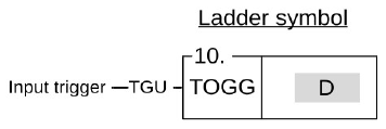
6-15 TOGGLE SWITCH(TOGG)
FUN10
TOGG
TOGGLE SWITCH
(Changes the output status when the rising edge of control input occur)
FUN10
TOGG
Symbol
Operand
D: the coil number of the toggle switch
Range
Ope-rand
Y
M
SM
S
Y0
∣
Y1023
M0
∣
M9119
M9120
∣
M25599
S0
∣
S3104
D
○
○
○*
○
Description
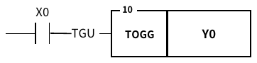
The coil D changes its status (from 1 to 0 and from 0 to 1) each time the input "TGU" is triggered from 0 to 1 (rising edge).
Example
Ladder Diagram
ST
IF F_TRIG(NOT X0) OR R_TRIG(X0)THEN Y0:=NOT Y0;
END_IF;
6-16 FAST ADDITION F(+)
FUN224 D P
F(+)
Fast ADDITION
(Performs addition of the data specified at Sa and Sb and stores the result in D)
FUN224 D P
F(+)
Symbol
Operand
Sa: Augend
Sb: Addend
D: Destination register to store the results
of the addition
Sa, Sb, D may combine with V, Z, P0~P9 to serve indirect addressing
Range
Operand
WX
WY
WM
WSM
WS
TMR
CTR
HR
IR
OR
SR
ROR
DR
K
XR
WX0
∣
WX1008
WY0
∣
WY1008
WM0
∣
WM9104
WM9120
∣
WM25584
WS0
∣
WS3088
T0
∣
T1023
C0
∣
C1279
R0
∣
R34767
R34768
∣
R34895
R35024
∣
R35151
R35280
∣
R43223
R43224
∣
R47319
D0
∣
D7999
16/32 – bit +/- number
V, Z
P0 ~ P9
Sa
○
○
○
○
○
○
○
○
○
○
○
○
○
○
○
Sb
○
○
○
○
○
○
○
○
○
○
○
○
○
○
○
D
○
○
○
○
○
○
○
○
○
○*
○*
○
○
FUN224 D P
F(+)
Fast ADDITION
(Performs addition of the data specified at Sa and Sb and stores the result in D)
FUN224 D P
F(+)
Description
Performs the fast addition control “EN”=1 or from 0→1 (P command) and the command is set to signed (S command), add Sa and Sb with the positive and negative number (Sign) algorithm and write the result into D.
Performs the fast addition control “EN”=1 or from 0→1 (P command) and the command is set to unsigned (U command), use the positive integer (Unsigned) algorithm to add Sa and Sb and write the result in D .
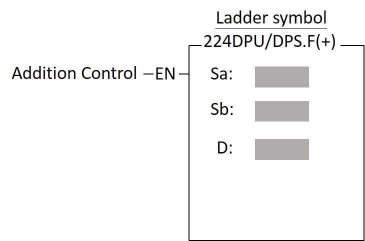
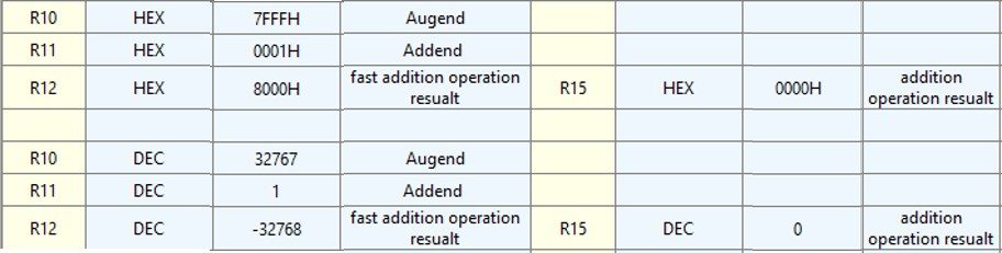
Compared with the addition operation of FUN11, the fast addition operation eliminates the overflow and underflow operations and flags, so the program execution time will be faster than the addition operation of FUN11, and the operation result will be the same as those obtained using high-level languages on a PC, such as C language, as shown in the left side of the figure below.
In addition, the calculation result of the addition operation of FUN11 will be different at the numerical boundary, for instance, sign arithmetic.
FUN224 D P
F(+)
Fast ADDITION
(Performs addition of the data specified at Sa and Sb and stores the result in D)
FUN224 D P
F(+)
Example
Ladder Diagram
ST
IF X0 THEN
R2 := R0 + R1;
END_IF
In case of " Signed ":
Sa
R0
12345
R0+R1=32770(32767+3)
Sb
R1
20425
⇩X0=
D
R2
-32766
32767+3>>-32768+2>>
-32766
※When adding more than 32767 (0x7FFF), it will become
-32768(0x8000)、-32767(0x8001)、-32766(0x8002)、…
-1(0xFFFF)、0(0x0000)
In case of " Unsigned ":
Sa
R0
12345
R0+R1=32770
Sb
R1
20425
⇩X0=
D
R2
32770
6-17 FAST SUBTRACTION F(-)
FUN225 D P
F(-)
Fast SUBTRACTION
(Performs subtraction of the data specified at Sa and Sb and stores the result in D)
FUN225 D P
F(-)
Symbol
Operand
Sa: minuend
Sb: Subtrahend
D: Destination register to store the results of the subtraction
Sa, Sb, D may combine with V, Z, P0~P9 to serve indirect addressing
Range
Operand
WX
WY
WM
WSM
WS
TMR
CTR
HR
IR
OR
SR
ROR
DR
K
XR
WX0
∣
WX1008
WY0
∣
WY1008
WM0
∣
WM9104
WM9120
∣
WM25584
WS0
∣
WS3088
T0
∣
T1023
C0
∣
C1279
R0
∣
R34767
R34768
∣
R34895
R35024
∣
R35151
R35280
∣
R43223
R43224
∣
R47319
D0
∣
D7999
16/32 – bit +/- number
V, Z
P0 ~ P9
Sa
○
○
○
○
○
○
○
○
○
○
○
○
○
○
○
Sb
○
○
○
○
○
○
○
○
○
○
○
○
○
○
○
D
○
○
○
○
○
○
○
○
○
○*
○*
○
○
Description
When the subtraction control “EN”=1 or from 0→1 (P command) and the command is set to signed (S command), subtract Sa and Sb with the positive and negative number (Sign) algorithm and write the result into D.
When the subtraction control “EN”=1 or from 0→1 (P command) and the command is set to unsigned (U command), subtract Sa and Sb with a positive integer (Unsigned) algorithm and write the result in D.
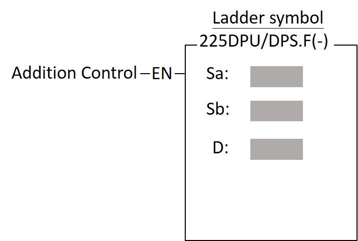
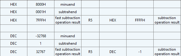
Compared with the subtraction operation of FUN12, the fast subtraction operation eliminates overflow and underflow operations and flags, so the program execution time is faster than the subtraction operation of FUN12, and the operation result will be the same as those obtained using high-level languages on a PC, such as C language, as shown in the left side of the figure below, and it will also be different from the calculation result of the subtraction operation of FUN12 at the numerical boundary, for instance, sign arithmetic.
FUN225 D P
F(-)
Fast SUBTRACTION
(Performs subtraction of the data specified at Sa and Sb and stores the result in D)
FUN225 D P
F(-)
FUN225 D P
F(-)
Fast SUBTRACTION
(Performs subtraction of the data specified at Sa and Sb and stores the result in D)
FUN225 D P
F(-)
Example
Ladder Diagram
ST
IF X0 THEN
R2 := R0 – R1;
END_IF
In case of " Signed ":
Sa
R0
-5
R0-R1=-32772(-32768-4)
Sb
R1
32767
⇩X0=
D
R2
32764
-32772>>-32768-4>>32767-3>>32764
※when less than -32768(0x8000) will becomes to 32767(0x7FFF)、32766(0x7FFE)….0(0x000)
In case of " Unsigned ":
Sa
R0
-5 (65531)
R0-R1=32764
Sb
R1
32767
⇩X0=
D
R2
32764
6-18 ADDITION(+)
FUN11 D P
(+)
ADDITION
(Performs addition of the data specified at Sa and Sb and stores the result in D)
FUN11 D P
(+)
Symbol
Operand
Sa: Augend
Sb: Addend
D: Destination register to store the results
of the addition
Sa, Sb, D may combine with V, Z, P0~P9 to serve indirect addressing
Range
Operand
WX
WY
WM
WSM
WS
TMR
CTR
HR
IR
OR
SR
ROR
DR
K
XR
WX0
∣
WX1008
WY0
∣
WY1008
WM0
∣
WM9104
WM9120
∣
WM25584
WS0
∣
WS3088
T0
∣
T1023
C0
∣
C1279
R0
∣
R34767
R34768
∣
R34895
R35024
∣
R35151
R35280
∣
R43223
R43224
∣
R47319
D0
∣
D7999
16/32 – bit +/- number
V, Z
P0 ~ P9
Sa
○
○
○
○
○
○
○
○
○
○
○
○
○
○
○
Sb
○
○
○
○
○
○
○
○
○
○
○
○
○
○
○
D
○
○
○
○
○
○
○
○
○
○*
○*
○
○
Description
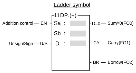
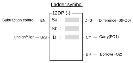
Performs the addition of the data specified at Sa and Sb using signed number and writes the results to a specified register D when the add control input "EN" =1 or from 0 to 1 (P instruction) and "U/S" = 0. If the result of addition is equal to 0 then set FO0(D = 0) to 1. If carry occurs (the result exceeds 32767 or 2147483647) then set FO1(CY) to 1. If borrow occurs (adding negative numbers resulting in a sum less than -32768 or -2147483648), then set the FO2(BR) to 1. All the FO statuses are retained until this instruction is executed again and overwritten by a new result.
Performs the addition of the data specified at Sa and Sb using unsigned number and writes the results to a specified register D when the add control input "EN" =1 or from 0 to 1 (P instruction) and "U/S" = 1. If the result of addition is equal to 0 then set FO0(D = 0) to 1. If carry occurs (the result exceeds 65535 or 4294967295) then set FO1(CY) to 1
FUN11 D P
(+)
ADDITION
(Performs addition of the data specified at Sa and Sb and stores the result in D)
FUN11 D P
(+)
Example
Ladder Diagram
ST
Sa
R0
12345
R0+R1=32770
Sb
R1
20425
⇩X0=
D
R2
2
32768+2=32770
Y0=1 (carry 1 represents +32768)
6-19 SUBTRACTION(-)
FUN12 D P
(-)
SUBTRACTION
(Performs subtraction of the data specified at Sa and Sb and stores the result in D)
FUN12 D P
(-)
Symbol
Operand
Sa: Minuend
Sb: Subtrahend
D: Destination register to store the results
of the subtraction
Sa, Sb, D may combine with V, Z, P0~P9 to serve indirect addressing
Range
Operand
WX
WY
WM
WSM
WS
TMR
CTR
HR
IR
OR
SR
ROR
DR
K
XR
WX0
∣
WX1008
WY0
∣
WY1008
WM0
∣
WM9104
WM9120
∣
WM25584
WS0
∣
WS3088
T0
∣
T1023
C0
∣
C1279
R0
∣
R34767
R34768
∣
R34895
R35024
∣
R35151
R35280
∣
R43223
R43224
∣
R47319
D0
∣
D7999
16/32 – bit +/- number
V, Z
P0 ~ P9
Sa
○
○
○
○
○
○
○
○
○
○
○
○
○
○
○
Sb
○
○
○
○
○
○
○
○
○
○
○
○
○
○
○
D
○
○
○
○
○
○
○
○
○
○*
○*
○
○
Description
Performs the subtraction of the data specified at Sa and Sb using signed number and writes the results to a specified register D when the subtract control input "EN" =1 or from 0 to 1 (P instruction) and "U/S" =0”. If the result of subtraction is equal to 0 then set FO0(D=0) to 1. If carry occurs (subtracting a negative number from a positive number and the result exceeds +32767 or +2147483647), then set FO1(CY) to 1. If borrow occurs (subtracting a positive number from a negative number and the resulted difference is less than -32768 or -2147483648), then set FO2(BR) to 1. All the FO statuses are retained until this instruction is executed again and overwritten by a new result.
FUN12 D P
(-)
SUBTRACTION
(Performs subtraction of the data specified at Sa and Sb and stores the result in D)
FUN12 D P
(-)
When the subtraction control "EN"=1 or from 0→1 (P command) and "U/S"=1, subtract Sa and Sb with the positive integer (Unsign) algorithm and write the result to D. At the same time, if the difference is 0, FO0 (D=0) is set to 1, and if a borrow occurs (Sa-Sb<0), FO2 (BR) is set to 1.
Example
Ladder Diagram
ST
Sa
R0
-5
R0-R1=-32772
Sb
R1
32767
D
R2
-4
-32768-4=-32772
Y2=1
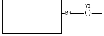
(borrow 1 represents-32768)Please refer to section 5.5
⇩X0=1
6-20 MULTIPLICATION(*)
FUN13 D P
(*)
MULTIPLICATION
(Performs multiplication of the data specified at Sa and Sb and stores the result in D)
FUN13 D P
(*)
Symbol
Operand
Sa: Multiplicand
Sb: Multiplier
D: Destination register to store the results
of the multiplication
Sa, Sb, D may combine with V, Z, P0~P9 to serve indirect addressing
Range
Operand
WX
WY
WM
WSM
WS
TMR
CTR
HR
IR
OR
SR
ROR
DR
K
XR
WX0
∣
WX1008
WY0
∣
WY1008
WM0
∣
WM9104
WM9120
∣
WM25584
WS0
∣
WS3088
T0
∣
T1023
C0
∣
C1279
R0
∣
R34767
R34768
∣
R34895
R35024
∣
R35151
R35280
∣
R43223
R43224
∣
R47319
D0
∣
D7999
16/32 – bit +/- number
V, Z
P0 ~ P9
Sa
○
○
○
○
○
○
○
○
○
○
○
○
○
○
○
Sb
○
○
○
○
○
○
○
○
○
○
○
○
○
○
○
D
○
○
○
○
○
○
○
○
○
○*
○*
○
○
Description
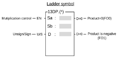
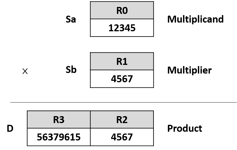
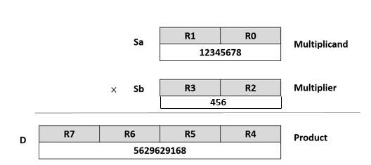
Performs the multiplication of the data specified at Sa and Sb using the signed number and writes the results to a specified register D when the multiplication control input "EN" =1 or from 0 to 1 (P instruction) and "U/S" = 0. If the product of multiplication is equal to 0 then set FO0(D=0) to 1. If the product is a negative number, then set FO1(D<0) to 1.
Performs the multiplication of the data specified at Sa and Sb using the unsigned number and writes the results to a specified register D when the multiplication control input "EN" =1 or from 0 to 1 (P instruction) and "U/S" =1 . If the product of multiplication is equal to 0 then set FO0(D=0) to 1.
FUN13 D P
(*)
MULTIPLICATION
(Performs multiplication of the data specified at Sa and Sb and stores the result in D)
FUN13 D P
(*)
Example 1
16-bit multiplication
Ladder Diagram
ST
FUN13 D P
(*)
MULTIPLICATION
(Performs multiplication of the data specified at Sa and Sb and stores the result in D)
FUN13 D P
(*)
Ladder Diagram
ST
6-21 DIVISION(/)
FUN14 D P
(/)
DIVISION
(Performs division of the data specified at Sa and Sb and stores the result in D)
FUN14 D P
(/)
Symbol
Operand
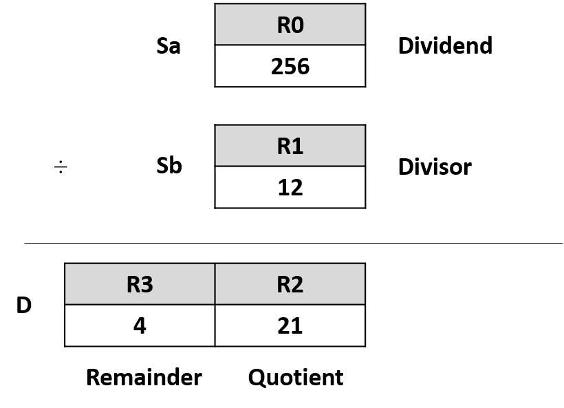
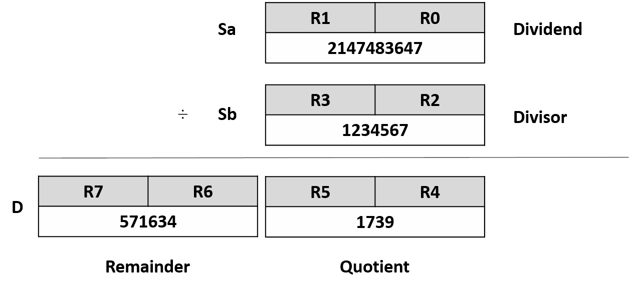
Sa: Dividend
Sb: Divisor
D: Destination register to store the results of the divison
Sa, Sb, D may combine with V, Z, P0~P9 to serve indirect addressing
Range
Operand
WX
WY
WM
WSM
WS
TMR
CTR
HR
IR
OR
SR
ROR
DR
K
XR
WX0
∣
WX1008
WY0
∣
WY1008
WM0
∣
WM9104
WM9120
∣
WM25584
WS0
∣
WS3088
T0
∣
T1023
C0
∣
C1279
R0
∣
R34767
R34768
∣
R34895
R35024
∣
R35151
R35280
∣
R43223
R43224
∣
R47319
D0
∣
D7999
16/32 – bit +/- number
V, Z
P0 ~ P9
Sa
○
○
○
○
○
○
○
○
○
○
○
○
○
○
○
Sb
○
○
○
○
○
○
○
○
○
○
○
○
○
○
○
D
○
○
○
○
○
○
○
○
○
○*
○*
○
○
FUN14 D P
(/)
DIVISION
(Performs division of the data specified at Sa and Sb and stores the result in D)
FUN14 D P
(/)
Description
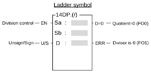
Performs the division of the data specified at Sa and Sb using the signed number and writes the results to a specified register D when the multiplication control input "EN" =1 or from 0 to 1 (P instruction) and "U/S" =0. If the quotient of division is equal to 0 then set FO0 to 1. If the divisor Sb=0 then set the error flag FO1 to 1 without executing the instruction.
Performs the division of the data specified at Sa and Sb using the unsigned number and writes the results to a specified register D when the multiplication control input "EN" =1 or from 0 to 1 (P instruction) and "U/S" =1. If the quotient of division is equal to 0 then set FO0 to 1. If the divisor Sb=0 then set the error flag FO1 to 1 without executing the instruction.
Example 1
16-bit division
Ladder Diagram
ST
IF X0 THEN
R2 := R0 / R1;
END_IF
FUN14 D P
(/)
DIVISION
(Performs division of the data specified at Sa and Sb and stores the result in D)
FUN14 D P
(/)
Example 2
32-bit division
Ladder Diagram
ST
IF X0 THEN
DR4 := DR0 / DR2;
END_IF
6-22 INCREMENT(+1)
FUN15 D P
(+1)
INCREMENT
(Adds 1 to the D value)
FUN15 D P
(+1)
Symbol
Operand
D: The register to be increased
D may combine with V, Z, P0~P9 to serve indirect addressing
Range
Operand
WY
WM
WSM
WS
TMR
CTR
HR
OR
SR
ROR
DR
XR
WY0
∣
WY1008
WM0
∣
WM9104
WM9120
∣
WM25584
WS0
∣
WS3088
T0
∣
T1023
C0
∣
C1279
R0
∣
R34767
R35024
∣
R35151
R35280
∣
R43223
R43224
∣
R47319
D0
∣
D7999
V, Z
P0 ~ P9
D
○
○
○
○
○
○
○
○
○*
○*
○
○
Description
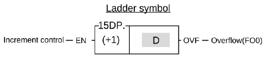
Adds 1 to the register D when the increment control input "EN" =1 or from 0 to 1 (P instruction). If the value of D is already at the upper limit of positive number 32767 or 2147483647, adding one to this value will change it to the lower limit of negative number -32768 or -2147483648. At the same time, the overflow flag FO0 (OVF) is set to 1.
Please refer to Section 5.4 for details on overflow.
FUN15 D P
(+1)
INCREMENT
(Adds 1 to the D value)
FUN15 D P
(+1)
Example
16-bit increment register
Ladder Diagram
ST
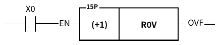
IF R_TRIG( S:= X0 ) THEN
R0V++ ;
END_IF
WHEN V=100,0+100=100
D
R100
1
⇩X0=
D
R100
2
6-23 DECREMEMT(-1)
FUN16 D P
(-1)
DECREMENT
(Subtracts 1 from the D value)
FUN16 D P
(-1)
Symbol
Operand
D : The register to be decreased
D may combine with V, Z, P0~P9 to serve indirect addressing
Range
Operand
WY
WM
WSM
WS
TMR
CTR
HR
OR
SR
ROR
DR
XR
WY0
∣
WY1008
WM0
∣
WM9104
WM9120
∣
WM25584
WS0
∣
WS3088
T0
∣
T1023
C0
∣
C1279
R0
∣
R34767
R35024
∣
R35151
R35280
∣
R43223
R43224
∣
R47319
D0
∣
D7999
V, Z
P0 ~ P9
D
○
○
○
○
○
○
○
○
○*
○*
○
○
Description
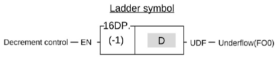
Subtracts 1 from the register D when the decrement control input "EN" =1 or from 0 to 1 ( P instruction). If the value of D is already at the lower limit of negative number -32768 or -2147483648, subtracting one from this value will change it to the upper limit of positive number 32767 or 2147483647. At the same time, the underflow flag FO0 (UDF) is set to 1.
Please refer to section 5.4 for detailed description of missing bits.
Example
16-bit decrement register
Ladder Diagram
ST
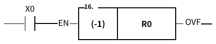
IF R_TRIG( S:= X0 ) THEN
R0– ;
END_IF
FUN16 D P
(-1)
DECREMENT
(Subtracts 1 from the D value)
FUN16 D P
(-1)
D
R0
0
⇩X0=
D
R0
-1
6-24 COMPARE(CMP)
FUN17 D P
CMP
COMPARE
(Compares the data of Sa and Sb and outputs the results to function Outputs)
FUN17 D P
CMP
Symbol
Operand
Sa: The register to be compared
Sb: The register to be compared
Sa, Sb may combine with V, Z, P0~P9 to serve indirect addressing
Range
Operand
WX
WY
WM
WSM
WS
TMR
CTR
HR
IR
OR
SR
ROR
DR
K
XR
WX0
∣
WX1008
WY0
∣
WY1008
WM0
∣
WM9104
WM9120
∣
WM25584
WS0
∣
WS3088
T0
∣
T1023
C0
∣
C1279
R0
∣
R34767
R34768
∣
R34895
R35024
∣
R35151
R35280
∣
R43223
R43224
∣
R47319
D0
∣
D11999
16/32 bit
+/-number
V、Z
P0~P9
Sa
○
○
○
○
○
○
○
○
○
○
○
○
○
○
○
Sb
○
○
○
○
○
○
○
○
○
○
○
○
○
○
○
Description
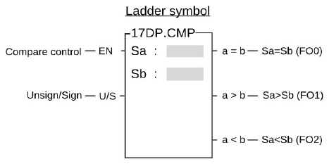
Compares the data of Sa and Sb using signed number when the compare control input "EN" =1 or from 0 to 1 (P instruction) and "U/S" =0. If the data of Sa is equal to Sb, then set FO0 to 1. If the data of Sa>Sb, then set FO1 to 1. If the data of Sa<Sb, then set FO2 to 1. If the data of Sa < Sb, then set the FO2 to 1.
Compares the data of Sa and Sb using unsigned number when the compare control input "EN" =1 or from 0 to 1 (P instruction) and "U/S" =1. If the data of Sa is equal to Sb, then set FO0 to 1. If the data of Sa>Sb, then set FO1 to 1. If the data of Sa<Sb, then set FO2 to 1. If the data of Sa < Sb, then set the FO2 to 1.
FUN17 D P
CMP
COMPARE
(Compares the data of Sa and Sb and outputs the results to function Outputs)
FUN17 D P
CMP
Example
Compares the data of 16-bit register
Ladder Diagram
ST
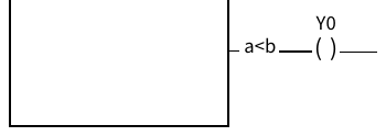
From the above example, we first assume the data of R0 is 1 and R1 is 2, and then compare the data by executing the CMP instruction. The FO0 and FO1 are set to 0 and FO2 (a<b) is set to 1 since a<b.
If you want to have the compound results, such as≧、≦、< > etc., please send =、< and > results to relay first and then combine the result from the relays.
6-25 LOGICAL AND(AND)
FUN18 D P
AND
LOGICAL AND
FUN18 D P
AND
Symbol
Operand
Sa: The register to be ANDed
Sb: The register to be ANDed
D: The register to store the result of AND
The Sa, Sb, D may combine with V, Z, P0~P9 to serve indirect addressing application
Range
Operand
WX
WY
WM
WSM
WS
TMR
CTR
HR
IR
OR
SR
ROR
DR
K
WX0
∣
WX1008
WY0
∣
WY1008
WM0
∣
WM9104
WM9120
∣
WM25584
WS0
∣
WS3088
T0
∣
T1023
C0
∣
C1279
R0
∣
R34767
R34768
∣
R34895
R35024
∣
R35151
R35280
∣
R43223
R43224
∣
R47319
D0
∣
D11999
16/32 bit
+/-number
Sa
○
○
○
○
○
○
○
○
○
○
○
○
○
○
Sb
○
○
○
○
○
○
○
○
○
○
○
○
○
○
D
○
○
○
○
○
○
○
○
○
○*
○*
○
Description
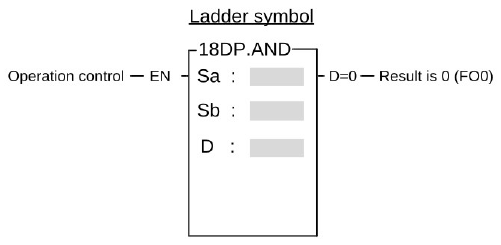
Performs logical AND operation for the data of Sa and Sb when the operation control input "EN" =1 or from 0 to 1 (P instruction). This operation compares the corresponding bits of Sa and Sb (B0~B15 or B0~B31). The bit in the D is set to 1 if both of the corresponding bit data of Sa and Sb is 1. The bit in the D is set to 0 if one of the corresponding bits is 0.
FUN18 D P
AND
LOGICAL AND
FUN18 D P
AND
Example
Operation of 16-bit logical AND
Ladder Diagram
ST
IF X0 THEN
R2 := R0 & R1 ;
END_IF
B15 B0
↓ ↓
Sa
R0
1
0
1
1
1
0
1
1
0
1
1
0
1
1
0
1
Sb
R1
1
1
1
0
1
1
1
0
1
0
1
0
0
1
1
0
⇩X0=
B15 B0
↓ ↓
D
R2
1
0
1
0
1
0
1
0
0
0
1
0
0
1
0
0
6-26 LOGICAL(OR)
FUN19 D P
OR
LOGICAL OR
FUN19 D P
OR
Symbol
Operand
Sa: The register to be ORed
Sb: The register to be ORed
D: The register to store the result of OR
The Sa, Sb, D may combine with V, Z, P0~P9 to serve indirect addressing
Range
Operand
WX
WY
WM
WSM
WS
TMR
CTR
HR
IR
OR
SR
ROR
DR
K
XR
WX0
∣
WX1008
WY0
∣
WY1008
WM0
∣
WM25584
WM9120
∣
WM25584
WS0
∣
WS3088
T0
∣
T1023
C0
∣
C1279
R0
∣
R34767
R34768
∣
R34895
R35024
∣
R35151
R35280
∣
R43223
R43224
∣
R47319
D0
∣
D7999
16/32-bit
+/-number
V, Z
P0 ~ P9
Sa
○
○
○
○
○
○
○
○
○
○
○
○
○
○
○
Sb
○
○
○
○
○
○
○
○
○
○
○
○
○
○
○
D
○
○
○
○
○
○
○
○
○
○*
○*
○
○
Description
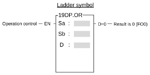
Operation of 16-bit logical OR
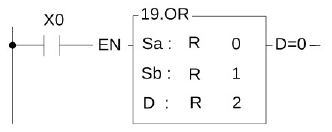
Performs logical OR operation for the data of Sa and Sb when the operation control input "EN" =1 or from 0 to 1 (P instruction). This operation compares the corresponding bits of Sa and Sb (B0~B15 or B0~B31). The bit in the D is set to 1 if one of the corresponding of Sa or Sb is 1. The bit in the D is set to 0 if both of the corresponding bits of Sa and Sb is 0.
FUN19 D P
OR
LOGICAL OR
FUN19 D P
OR
Example
Operation of 16-bit logical OR
Ladder diagram
ST
B15 B0
↓ ↓
Sa
R0
1
0
1
1
1
0
1
1
0
1
1
0
1
1
0
1
Sb
R1
1
1
1
0
1
1
1
0
1
0
1
0
0
1
1
0
⇩X0=1
B15 B0
↓ ↓
D
R2
1
1
1
1
1
1
1
1
1
1
1
0
1
1
1
1
6-27 BIN→BCD CONVERSION
FUN20D P
→BCD
BIN→BCD CONVERSION
(Converts BIN data of the device specified at S into BCD and stores the result in D)
FUN20D P
→BCD
Symbol
Operand
S: The register to be converted
D: The register to store the converted data (BCD code)
The S, D may combine with V, Z, P0~P9 to serve indirect addressing
Range
Operand
WX
WY
WM
WSM
WS
TMR
CTR
HR
IR
OR
SR
ROR
DR
K
XR
WX0
∣
WX1008
WY0
∣
WY1008
WM0
∣
WM25584
WM9120
∣
WM25584
WS0
∣
WS3088
T0
∣
T1023
C0
∣
C1279
R0
∣
R34767
R34768
∣
R34895
R35024
∣
R35151
R35280
∣
R43223
R43224
∣
R47319
D0
∣
D7999
16/32-bit
+/-number
V, Z
P0 ~ P9
S
○
○
○
○
○
○
○
○
○
○
○
○
○
○
○
D
○
○
○
○
○
○
○
○
○
○*
○*
○
○
Description
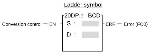
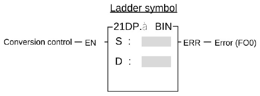
FB-PLC uses binary code to store and to execute calculations. If want to send the internal PLC data to the external displays such as seven-segment displays, it is more convenient for us to read the result on screen by converting the BIN data to BCD data. For example, it is more clear for us to read the reading "12" instead of the binary code "1100."
Converts BIN data of the device specified at S into BCD and writes the result in D when the operation control input "EN" =1 or from 0 to 1 (P instruction). If the data in S is not a BCD value (0~9999 or 0~9999999), then the error flag FO0 is set to 1 and the old data of D are retained.
FUN20D P
→BCD
BIN→BCD CONVERSION
(Converts BIN data of the device specified at S into BCD and stores the result in D)
FUN20D P
→BCD
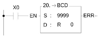
Example
16-bit BIN → BCD conversion
Ladder diagram
ST
IF X0 THEN
ToBCD( S:= 9999, D=> R0);
END_IF
B15 B0
↓ ↓
S
K
0
0
1
0
0
1
1
1
0
0
0
0
1
1
1
1
⇩X0=1
B15 B0
↓ ↓
D
R0
1
0
0
1
1
0
0
1
1
0
0
1
1
0
0
1
6-29 BCD→BIN CONVERSION
FUN21D P
→BIN
BCD→BIN CONVERSION
(Converts BCD data of the device specified at S into BIN and stores the result in D)
FUN21D P
→BIN
Symbol
Operand
S: The register to be converted
D: The register to store the converted data (BIN code)
The S, D may combine with V, Z, P0~P9 to serve indirect addressing
Range
Operand
WX
WY
WM
WSM
WS
TMR
CTR
HR
IR
OR
SR
ROR
DR
K
XR
WX0
∣
WX1008
WY0
∣
WY1008
WM0
∣
WM25584
WM9120
∣
WM25584
WS0
∣
WS3088
T0
∣
T1023
C0
∣
C1279
R0
∣
R34767
R34768
∣
R34895
R35024
∣
R35151
R35280
∣
R43223
R43224
∣
R47319
D0
∣
D7999
16/32-bit
+/-number
V, Z
P0 ~ P9
S
○
○
○
○
○
○
○
○
○
○
○
○
○
○
○
D
○
○
○
○
○
○
○
○
○
○*
○*
○
○
Description
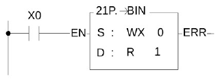
The decimal (BCD) data must be converted to binary (BIN) data first in order for PLC to accept the data which is originally in decimal unit (BCD code) inputted from external device such as digital switch because the BCD data can not be accepted by PLC for its operations.
Converts BCD data of the device specified at S into BIN and writes the result in D when the operation control input "EN" =1 or from 0 to 1 (P instruction). If the data in S is not in BCD, then the error flag FO0 is set to 1 and the old data of D are retained.
Constant is converted to BIN automatically when store in program and can not be used as a source operand of this function.
FUN21D P
→BIN
BCD TO BIN CONVERSION
(Converts BCD data of the device specified at S into BIN and stores the result in D)
FUN21D P
→BIN
Example
16-bit BCD to BIN conversion
Ladder diagram
ST
IF R_TRIG( S:= X0 ) THEN
ToBIN( S:= WX0 , D=> R1);
END_IF
X15 X0
↓ 1 2 3 4 H ↓
S
WX0
0
0
0
1
0
0
1
0
0
0
1
1
0
1
0
0
⇩X0=1
B15 B0
↓ ↓
D
R1
0
0
0
0
0
1
0
0
1
1
0
1
0
0
1
0
6-30 Modulo(MOD)
FUN226D P
MOD
Modulo(Remainder)
FUN226D P
MOD
Symbol
Operand
Sa: Dividend
Sb: Divisor
D: Destination register to store the results
(remainder) of the divison
Sa, Sb, D may combine with V, Z, P0~P9 to serve indirect addressing
Range
Operand
WX
WY
WM
WM
WS
TMR
CTR
HR
IR
OR
SR
ROR
DR
K
XR
WX0
∣
WX1008
WY0
∣
WY1008
WM0
∣
WM9104
WM9120
∣
WM25584
WS0
∣
WS3088
T0
∣
T1023
C0
∣
C1279
R0
∣
R34767
R34768
∣
R35023
R35024
∣
R35279
R35280
∣
R43223
R43224
∣
R47319
D0
∣
D7999
16/32-bit +/- number
V, Z
P0 ~ P9
D
○
○
○
○
○
○
○
○
○
○
○
○
○
○
○
○
○
○
○
○
○
○
○
○
○
○
○
○
○
○
○
○
○
○
○
○
○
○
○
○*
○*
○
○
Description
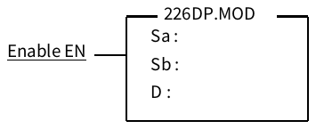
Writes the results to a specified register D when the multiplication control input "EN" =1 or from 0 to 1 (P instruction).
※When the divisor is 0, it will be regarded as the quotient is 0, and the remainder is equal to the dividend. When using it, please note that the divisor should not be entered as 0, otherwise you will get remainder = dividend
FUN226D P
MOD
Modulo(Remainder)
FUN226D P
MOD
Example
Ladder Diagram
ST
IF X0 Then
R2 := R0 MOD R1;
END_IF
When X0 is ON, Sa will be divided by Sb, and the remainder will be written into D.
For example: If Sa = 5 and Sb = 3, then when X0 is ON, D will be written with 2.
Was this page helpful?
Thanks for your feedback!
Tip: press ←→ to switch chapters, Ctrl+K to search


 Example 1
 Example 2
 Example 1