7-1 Arithmetical Operation Instructions(FUN24~33)
7-1-1 Summation of Block Data(SUM)
|
FUN24 D P SUM |
SUM (Summation of block data) |
FUN24 D P SUM |
|||||||||||||||||||||||||||||||||||||||||||||||||||||||||||||||||||||||||||
|
Symbol |
|||||||||||||||||||||||||||||||||||||||||||||||||||||||||||||||||||||||||||||
|
|
S: Starting number of source register N: Number of registers to be summed D: The register which stored the result (summation) S, N, D, can associate with V, Z, P0~P9 index register to serve the indirect addressing application. |
||||||||||||||||||||||||||||||||||||||||||||||||||||||||||||||||||||||||||||
|
|||||||||||||||||||||||||||||||||||||||||||||||||||||||||||||||||||||||||||||
|
Description |
|||||||||||||||||||||||||||||||||||||||||||||||||||||||||||||||||||||||||||||
|
|||||||||||||||||||||||||||||||||||||||||||||||||||||||||||||||||||||||||||||

|
Example 1 |
When X0 changes from OFF→ON, following instruction will calculates the summation for 16-bit data |
||||
R1=0031H R2=0032H R3=0033H R4=0034H R5=0035H
|
|||||
|
Example 2 |
When X0 is ON, it calculates the summation for 32-bit data. |
||||
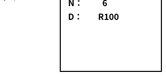
R1~R0=00310030H R3~R2=00330032H 🡺 R101~R100=00A5009BH R5~R4=00410039H
|
|||||
 R0=0030H
7-1-2 Average of Block Data (MEAN)
|
FUN25 D P MEAN |
MEAN (Average of the block data) |
FUN25 D P MEAN |
|||||||||||||||||||||||||||||||||||||||||||||||||||||||||||||||||||||||||||
|
Symbol |
|||||||||||||||||||||||||||||||||||||||||||||||||||||||||||||||||||||||||||||
|
|
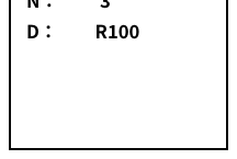
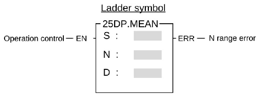
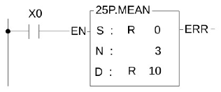
S: Source register number N: Number of registers to be averaged (N units of successive registers starting from S) D: Register number for storing result (mean value) The S, N, D may combine with V, Z, P0~P9 to serve indirect address application |
||||||||||||||||||||||||||||||||||||||||||||||||||||||||||||||||||||||||||||
|
|||||||||||||||||||||||||||||||||||||||||||||||||||||||||||||||||||||||||||||
|
Description |
|||||||||||||||||||||||||||||||||||||||||||||||||||||||||||||||||||||||||||||
|
|||||||||||||||||||||||||||||||||||||||||||||||||||||||||||||||||||||||||||||
|
FUN25 D P MEAN |
MEAN (Average of the block data) |
FUN25 D P MEAN |
|||||||||||||||||||||||
|
Example |
|||||||||||||||||||||||||
|
|||||||||||||||||||||||||
7-1-3 Take the Negative Value (NEGATION)
|
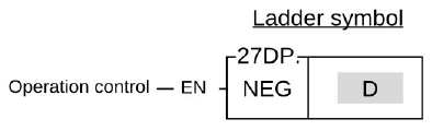
FUN27 D P NEG |
NEGATION (Take the negative value) |
FUN27 D P NEG |
|||||||||||||||||||||||||||||||||||||||
|
Symbol |
|||||||||||||||||||||||||||||||||||||||||
|
|
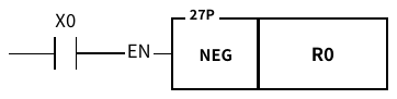
D : Register to be negated D may combine with V, Z, P0~P9 to serve indirect address application |
||||||||||||||||||||||||||||||||||||||||
|
|||||||||||||||||||||||||||||||||||||||||
|
Description |
|||||||||||||||||||||||||||||||||||||||||
|
|||||||||||||||||||||||||||||||||||||||||
|
Example |
|||||||||||||||||||||||||||||||||||||||||
|
|||||||||||||||||||||||||||||||||||||||||
|
|||||||||||||||||||||||||||||||||||||||||
7-1-4 Take the Absolute Value (ABSOLUTE)
|
FUN28 D P ABS |
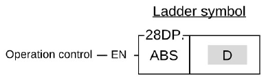
ABSOLUTE (Take the absolute value) |
FUN28 D P ABS |
|||||||||||||||||||||||||||||||||||||||
|
Symbol |
|||||||||||||||||||||||||||||||||||||||||
|
|
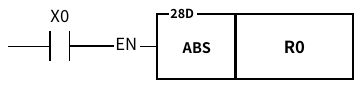
D : Register to be taken absolute value. D may combine with V, Z, P0~P9 to serve indirect address application. |
||||||||||||||||||||||||||||||||||||||||
|
|||||||||||||||||||||||||||||||||||||||||
|
Description |
|||||||||||||||||||||||||||||||||||||||||
|
|||||||||||||||||||||||||||||||||||||||||
|
Example |
|||||||||||||||||||||||||||||||||||||||||
|
|||||||||||||||||||||||||||||||||||||||||
|
|||||||||||||||||||||||||||||||||||||||||
7-1-5 Linear Conversion (LCNV)
|
FUN33 P LCNV |
Linear Conversion (LCNV) |
FUN33 P LCNV |
|||||||||||||||||||||||||||||||||||||||||||||||||||||||||||||||
|
Symbol |
|||||||||||||||||||||||||||||||||||||||||||||||||||||||||||||||||
|
|
Md: Operation mode, 0~3 S: Starting address of the source data Ts: Starting address of the parameter table for conversion D: Starting address to store the result L: Quantity of conversion entry, 1~64 |
||||||||||||||||||||||||||||||||||||||||||||||||||||||||||||||||
|
|||||||||||||||||||||||||||||||||||||||||||||||||||||||||||||||||
|
Description |
|||||||||||||||||||||||||||||||||||||||||||||||||||||||||||||||||
|
|||||||||||||||||||||||||||||||||||||||||||||||||||||||||||||||||

|
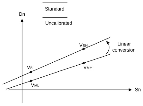
Expression 1: Two points calibration method Fill the conversion parameter table with the low value of measurement(VML), high value of measurement (VMH), and the corresponding low value of standard (VSL), high value of standard (VSH); the converted result (Dn) will be generated from the source data(Sn) through the formula shown below:
A = (VSL-VSH/VML-VMH)×10000 B = VSL-(VML×A/10000) Dn = (Sn×A/10000)+B
VML=Minmum of analog input VMH=Maximum of analog input VSL=Minmum of engineering range VSH=Maximum of engineering range |
|
FUN33 P LCNV |
Linear Conversion (LCNV) |
FUN33 P LCNV |
|
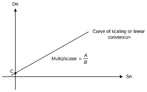
Expression 2 : Multiplicator+Offset method Fill the conversion parameter table with the values of multiplier(A), divisor(B) and offset(C); The converted result (Dn) will be generated from the source data (Sn) through the formula shown below:
Dn =[(Sn×A)/B]+C The range of each operand as below: A = 1~65535 B = 1~65535 C = -32768~32767 Sn = 0~65535 Dn = -32768~32767 Description of operation mode
|
||
|
FUN33 P LCNV |
Linear Conversion (LCNV) |
FUN33 P LCNV |
||||
|
Example 1 |
Mode 0 of linear conversion |
|||||
|
||||||
|
FUN33 P LCNV |
Linear Conversion (LCNV) |
FUN33 P LCNV |
||||||||||||||||||||||||||||||||||||||||
|
Ts
S D
|
||||||||||||||||||||||||||||||||||||||||||
|
Example 2 |
Mode 1 of linear conversion |
|||||||||||||||||||||||||||||||||||||||||
Description:
|
||||||||||||||||||||||||||||||||||||||||||
|
FUN33 P LCNV |
Linear Conversion (LCNV) |
FUN33 P LCNV |
|||||||||||||||||||||||||||||
|
Ts VML_0 VMH_0 VSL_0 VSH_0 VML_1 VMH_1 VSL_1 VSH_1 VML_2 VMH_2 VSL_2 VSH_2
S D
|
|||||||||||||||||||||||||||||||
|
FUN33 P LCNV |
Linear Conversion (LCNV) |
FUN33 P LCNV |
||||
|
Example 3 |
Mode 2 of linear conversion |
|||||
Description: When M0 = 1, it will perform the mode 2 operation of linear conversion, where R100 is the starting address of the source data, R1000 is the starting address of the table of the conversion parameters A, B, C, the quantity is 6, and R2000~R2005 will store the converted results. |
||||||
|
FUN33 P LCNV |
Linear Conversion (LCNV) |
FUN33 P LCNV |
|||||||||||||||||||||||||||||||||||
|
S D
|
|||||||||||||||||||||||||||||||||||||
|
Example 4 |
Mode 3 of linear conversion |
||||||||||||||||||||||||||||||||||||
Description:
|
|||||||||||||||||||||||||||||||||||||
 Ts
|
FUN33 P LCNV |
Linear Conversion (LCNV) |
FUN33 P LCNV |
||||||||||||||||||||||||||||||||||
|
S D
|
||||||||||||||||||||||||||||||||||||
 Ts
7-1-6 Multiple Linear Conversion (MLC)
|
FUN34 P MLC |
Multiple Linear Conversion (MLC) |
FUN34 P MLC |
||||||||||||||||||||||||||||||||||||||||||||||||||||||||||||||||
|
Symbol |
||||||||||||||||||||||||||||||||||||||||||||||||||||||||||||||||||
|
|
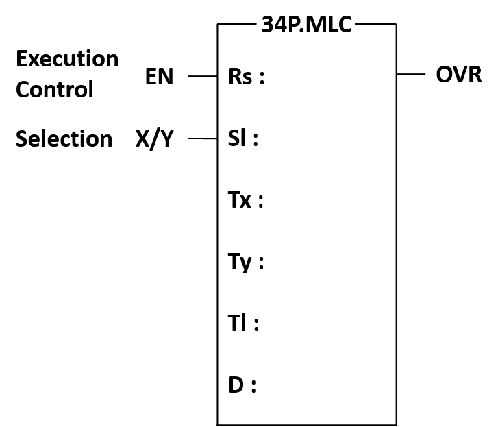
Rs: Starting address of the source data Sl: Quantity of source data, 1~64 Tx: Starting address of X table Ty: Starting address of Y table Tl: Quantity of table, 2~255 D: Starting address to store the result |
|||||||||||||||||||||||||||||||||||||||||||||||||||||||||||||||||
|
||||||||||||||||||||||||||||||||||||||||||||||||||||||||||||||||||
|
FUN34 P MLC |
Multiple Linear Conversion (MLC) |
FUN34 P MLC |
|
Description |
||
|
||
|
FUN34 P MLC |
Multiple Linear Conversion (MLC) |
FUN34 P MLC |
|
Expression: The entities of Tx conversion parameter table must be in ascending sequence to have correct linear conversion; the entities of Ty conversion parameter table can either be in ascending or descending sequence. When executing this instruction, it will search the located section by comparing entities of the table with source data, and then calculate the linear conversion according to the following expression: Vy = (Vx-Tx_n) × (Ty_n+1-Ty_n/Tx_n+1-Tx_n) + Ty_n if X/Y=0 Vx = (Vy-Ty_n) × (Tx_n+1-Tx_n/Ty_n+1-Ty_n) + Tx_n if X/Y=1 Value of Operand Vy、Vx、Tx_n、Tx_n+1、Ty_n、Ty_n+1 must be -32768~32767
|
||
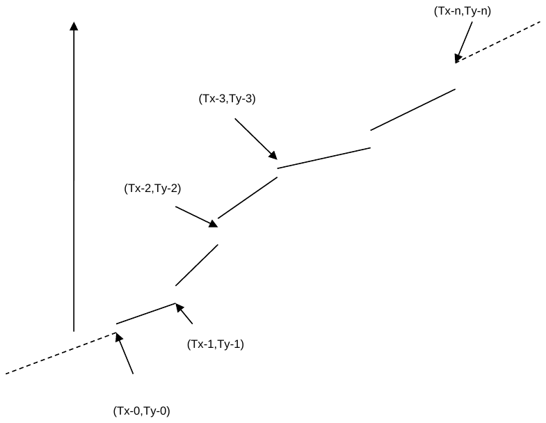 Figure of multiple linear conversion:
|
FUN34 P MLC |
Multiple Linear Conversion (MLC) |
FUN34 P MLC |
||||
|
Example 1 |
||||||
|
||||||
|
FUN34 P MLC |
Multiple Linear Conversion (MLC) |
FUN34 P MLC |
|
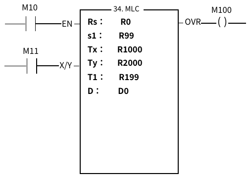
Description: When M10=1、M11=0, R0 is the starting address of source data、R99 is the quantity of source data, R1000 is the starting address of Tx conversion parameter table, R2000 is the starting address of Ty conversion parameter table, R199 is the quantity of table; the source data R0~R5 will be calculated the linear conversion according to Tx and Ty table between four sections, then store the results into D0~D5.
|
||
|
|
||

|
FUN34 P MLC |
Multiple Linear Conversion (MLC) |
FUN34 P MLC |
||||
|
Example 2 |
||||||
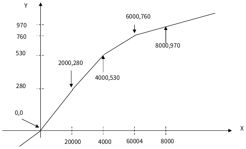
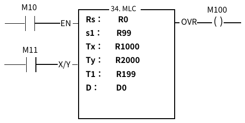
Description: When M10=1, M11=0, take R0 as the starting source data and R99 as the source data length, according to the Tx conversion table starting from R1000 and the Ty conversion table starting from R2000, and R199 as the conversion table Length, perform 5-segment linear conversion operation on source data such as R0~R5, and store the conversion results in temporary registers D0~D5. In this example, when the value of the source data is less than or equal to 2000, the corresponding value is 280; when the value of the source data is greater than or equal to 8000, the corresponding value is 970. |
||||||
|
FUN34 P MLC |
Multiple Linear Conversion (MLC) |
FUN34 P MLC |
|
|
||

|
FUN34 P MLC |
Multiple Linear Conversion (MLC) |
FUN34 P MLC |
||||
|
Example 3 |
||||||
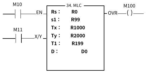
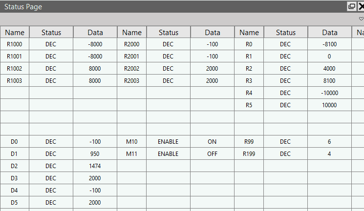
Description: When M10=1, M11=0, R0 is the starting address of source data, R99 is the quantity of source data, R1000 is the starting address of Tx conversion parameter table, R2000 is the starting address of Ty conversion parameter table, R199 is the quantity of table; the source data R0~R5 will be calculated the linear conversion according to Tx and Ty table between three sections, then store the results into D0~D5. T In this example, when the value of the source data is -8000~8000, the corresponding value is -100~2000 according to the linear conversion shown in the figure below; when the value of the source data is ≧8000, the corresponding value is 2000; and the corresponding values are all -100. |
||||||
|
FUN34 P MLC |
Multiple Linear Conversion (MLC) |
FUN34 P MLC |
||||
|
|
||||||
|
Example 4 |
||||||
|
||||||

|
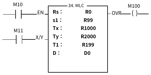
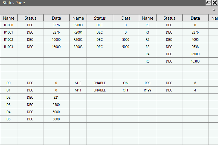
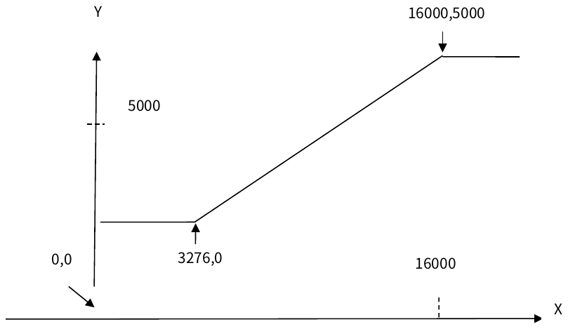
Description: When M10=1, M11=0, R0 is the starting address of source data, R99 is the quantity of source data, R1000 is the starting address of Tx conversion parameter table, R2000 is the starting address of Ty conversion parameter table, R199 is the quantity of table; the source data R0~R5 will be calculated the linear conversion according to Tx and Ty table between three sections, then store the results into D0~D5.T In this example, when the value of the source data is 3276~16000, the corresponding value is 0~5000 according to the linear conversion shown in the figure below; when the value of the source data is ≧16000, the corresponding value is 5000; all are 0. |
|
|
7-2 Logical Operation Instructions (FUN35~36)
7-2-1 EXCLUSIVE OR (XOR)
|
FUN35 D P XOR |
EXCLUSIVE OR (XOR) |
FUN35 D P XOR |
|||||||||||||||||||||||||||||||||||||||||||||||||||||||||||||||||||||||||||
|
Symbol |
|||||||||||||||||||||||||||||||||||||||||||||||||||||||||||||||||||||||||||||
|
|
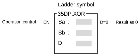
Sa: Source data a for exclusive or operation Sb: Source data b for exclusive or operation D: Register storing XOR results Sa, Sb, D may combine with V, Z, P0~P9 to serve indirect address application |
||||||||||||||||||||||||||||||||||||||||||||||||||||||||||||||||||||||||||||
|
|||||||||||||||||||||||||||||||||||||||||||||||||||||||||||||||||||||||||||||
|
Description |
|||||||||||||||||||||||||||||||||||||||||||||||||||||||||||||||||||||||||||||
|
|||||||||||||||||||||||||||||||||||||||||||||||||||||||||||||||||||||||||||||
|
FUN35 D P XOR |
EXCLUSIVE OR (XR) |
FUN35 D P XOR |
||||||||||||||||||||||||||||||||||||||||||||||||||||||||||
|
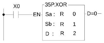
Example |
||||||||||||||||||||||||||||||||||||||||||||||||||||||||||||
⇩X0=
|
||||||||||||||||||||||||||||||||||||||||||||||||||||||||||||
7-2-2 EXCLUSIVE NOR (XNR)
|
FUN36 D P XNR |
EXCLUSIVE NOR (XNR) |
FUN36 D P XNR |
||||||||||||||||||||||||||||||||||||||||||||||||||||||||||||||||||||||||||||||||
|
Symbol |
||||||||||||||||||||||||||||||||||||||||||||||||||||||||||||||||||||||||||||||||||
|
|
Sa: Data a for XNR operation Sb: Data b for XNR operation D: Register storing XNR results Sa, Sb, D may combine with V, Z, P0~P9 to serve indirect address application |
|||||||||||||||||||||||||||||||||||||||||||||||||||||||||||||||||||||||||||||||||
|
||||||||||||||||||||||||||||||||||||||||||||||||||||||||||||||||||||||||||||||||||
|
Description |
||||||||||||||||||||||||||||||||||||||||||||||||||||||||||||||||||||||||||||||||||
|
||||||||||||||||||||||||||||||||||||||||||||||||||||||||||||||||||||||||||||||||||

|
FUN36 D P XNR |
EXCLUSIVE NOR (XNR) |
FUN36 D P XNR |
||||||||||||||||||||||||||||||||||||||||||||||||||||||||||
|
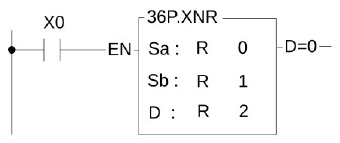
Example |
||||||||||||||||||||||||||||||||||||||||||||||||||||||||||||
⇩X0=
|
||||||||||||||||||||||||||||||||||||||||||||||||||||||||||||
7-3 Comparison Instructions (FUN37)
7-3-1 ZONE COMPARE (ZNCMP)
|
FUN37 D P ZNCMP |
ZONE COMPARE |
FUN37 D P ZNCMP |
||||||||||||||||||||||||||||||||||||||||||||||||||||||||||||||||||||||||||||||||
|
Symbol |
||||||||||||||||||||||||||||||||||||||||||||||||||||||||||||||||||||||||||||||||||
|
|
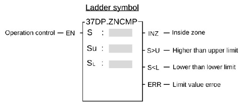
S: Register for zone comparison SU: The upper limit value SL: The lower limit value S, SU, SL may combine with V, Z, P0~P9 to serve indirect address application |
|||||||||||||||||||||||||||||||||||||||||||||||||||||||||||||||||||||||||||||||||
|
||||||||||||||||||||||||||||||||||||||||||||||||||||||||||||||||||||||||||||||||||
|
Description |
||||||||||||||||||||||||||||||||||||||||||||||||||||||||||||||||||||||||||||||||||
|
||||||||||||||||||||||||||||||||||||||||||||||||||||||||||||||||||||||||||||||||||
|
FUN37 D P ZNCMP |
ZONE COMPARE |
FUN37 D P ZNCMP |
||||||||||||||||||||
|
Example |
||||||||||||||||||||||
If want to get the status of out side the zone, you can use OUT NOT Y0.
Y0 X0= 1 ☞ Results of execution |
||||||||||||||||||||||

7-4 Data Movement Instructions(FUN40~50)
7-4-1 BIT READ (BITRD)
|
FUN40 D P BITRD |
BIT READ |
FUN40 D P BITRD |
||||||||||||||||||||||||||||||||||||||||||||||||||||||||||||||||
|
Symbol |
||||||||||||||||||||||||||||||||||||||||||||||||||||||||||||||||||
|
|
S: Source data to be read N: The bit number of the S data to be read out S, N may combine with V, Z, P0~P9 to serve indirect address application |
|||||||||||||||||||||||||||||||||||||||||||||||||||||||||||||||||
|
||||||||||||||||||||||||||||||||||||||||||||||||||||||||||||||||||
|
Description |
||||||||||||||||||||||||||||||||||||||||||||||||||||||||||||||||||
|
||||||||||||||||||||||||||||||||||||||||||||||||||||||||||||||||||

|
FUN40 D P BITRD |
BIT READ |
FUN40 D P BITRD |
||||||||||||||||||||||||
|
Example |
||||||||||||||||||||||||||
X15 X7 X0
N=7─────────────
|
||||||||||||||||||||||||||
 ⇩X50=
7-4-2 BIT WRITE (BITWR)
|
FUN41 D P BITWR |
BIT WRITE |
FUN41 D P BITWR |
||||||||||||||||||||||||||||||||||||||||||||||||||||||||||||
|
Symbol |
||||||||||||||||||||||||||||||||||||||||||||||||||||||||||||||
|
|
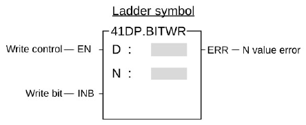
D: Register for bit write N: The bit number of the D register to be written. D, N may combine with V, Z, P0~P9 to serve indirect address application |
|||||||||||||||||||||||||||||||||||||||||||||||||||||||||||||
|
||||||||||||||||||||||||||||||||||||||||||||||||||||||||||||||
|
Description |
||||||||||||||||||||||||||||||||||||||||||||||||||||||||||||||
|
||||||||||||||||||||||||||||||||||||||||||||||||||||||||||||||
|
FUN41 D P BITWR |
BIT WRITE |
FUN41 D P BITWR |
||||
|
||||||
7-4-3 BIT MOVE (BITMV)
|
FUN42 D P BITMV |
BIT MOVE |
FUN42 D P BITMV |
||||||||||||||||||||||||||||||||||||||||||||||||||||||||||||||||||||||||||||||||||||||||||||||||
|
Symbol |
||||||||||||||||||||||||||||||||||||||||||||||||||||||||||||||||||||||||||||||||||||||||||||||||||
|
|
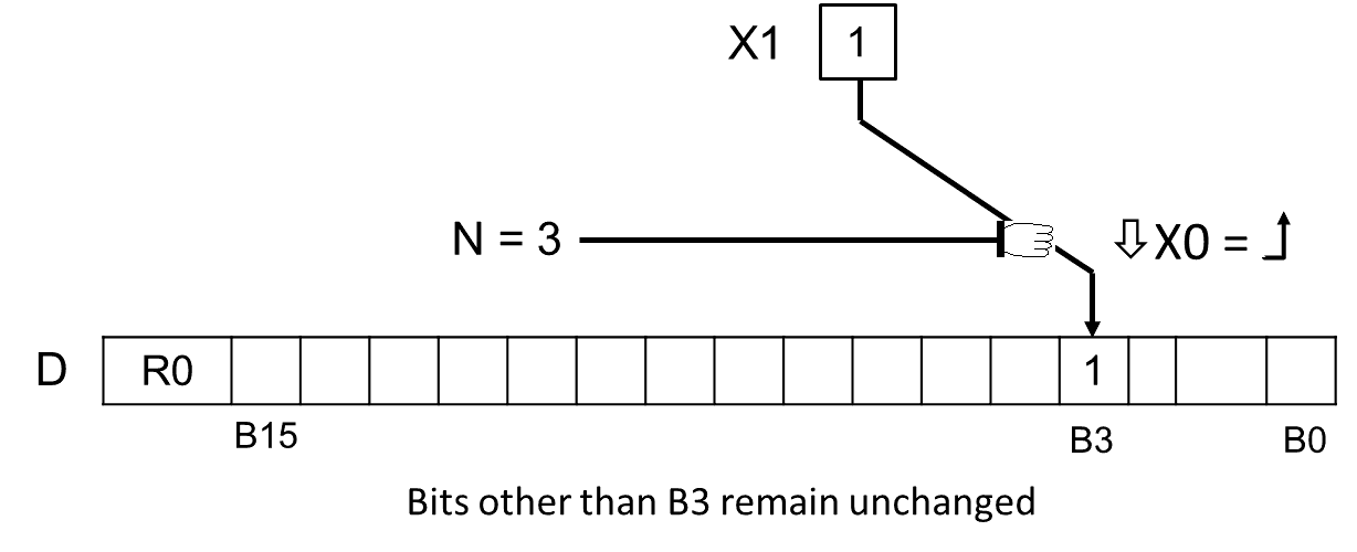
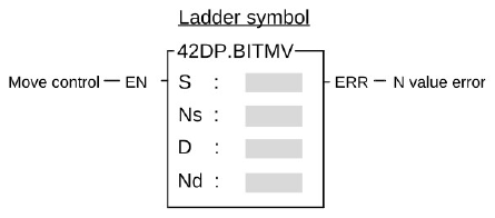
S: Source data to be moved Ns: Assign Ns bit within S as source bit D: Destination register to be moved Nd: Assign Nd bit within D as target bit S, Ns, D, Nd may combine with V, Z, P0~P9 to serve indirect address application |
|||||||||||||||||||||||||||||||||||||||||||||||||||||||||||||||||||||||||||||||||||||||||||||||||
|
||||||||||||||||||||||||||||||||||||||||||||||||||||||||||||||||||||||||||||||||||||||||||||||||||
|
Description |
||||||||||||||||||||||||||||||||||||||||||||||||||||||||||||||||||||||||||||||||||||||||||||||||||
|
||||||||||||||||||||||||||||||||||||||||||||||||||||||||||||||||||||||||||||||||||||||||||||||||||
|
FUN42 D P BITMV |
BIT MOVE |
FUN42 D P BITMV |
||||||||||||||||||||||||||||||||||||||||
|
Example |
||||||||||||||||||||||||||||||||||||||||||
X15 X11 X0
Ns=11─────── ⇩X50= Nd=7 ───────────
B15 B7 B0 |
||||||||||||||||||||||||||||||||||||||||||


7-4-4 NIBBLE MOVE (NBMV)
|
FUN43 D P NBMV |
NIBBLE MOVE |
FUN43 D P NBMV |
||||||||||||||||||||||||||||||||||||||||||||||||||||||||||||||||||||||||||||||||||||||||||||||||
|
Symbol |
||||||||||||||||||||||||||||||||||||||||||||||||||||||||||||||||||||||||||||||||||||||||||||||||||
|
|
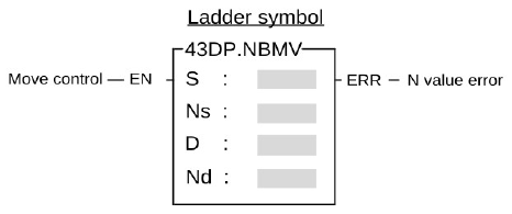
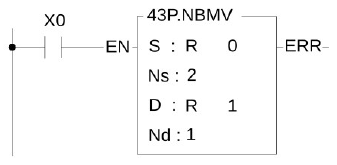
S: Source data to be moved Ns: Assign Ns nibble within S as source nibble D: Destination register to be moved Nd: Assign Nd nibble within D as target nibble S, Ns, D, Nd may combine with V, Z, P0~P9 to serve indirect address application |
|||||||||||||||||||||||||||||||||||||||||||||||||||||||||||||||||||||||||||||||||||||||||||||||||
|
||||||||||||||||||||||||||||||||||||||||||||||||||||||||||||||||||||||||||||||||||||||||||||||||||
|
Description |
||||||||||||||||||||||||||||||||||||||||||||||||||||||||||||||||||||||||||||||||||||||||||||||||||
|
||||||||||||||||||||||||||||||||||||||||||||||||||||||||||||||||||||||||||||||||||||||||||||||||||
|
FUN43 D P NBMV |
NIBBLE MOVE |
FUN43 D P NBMV |
||||||||||||||||||||||||||||||||||||||||
|
Example |
||||||||||||||||||||||||||||||||||||||||||
B15 B0
NB3 NB2 NB1 NB0 Ns=2 ─────── ⇩X0= Nd=1 ───────── NB3 NB2 NB1 NB0
B15 B0 |
||||||||||||||||||||||||||||||||||||||||||


7-4-5 BYTE MOVE (BYMV)
|
FUN44 D P BYMV |
BYTE MOVE |
FUN44 D P BYMV |
||||||||||||||||||||||||||||||||||||||||||||||||||||||||||||||||||||||||||||||||||||||||||||||||
|
Symbol |
||||||||||||||||||||||||||||||||||||||||||||||||||||||||||||||||||||||||||||||||||||||||||||||||||
|
|
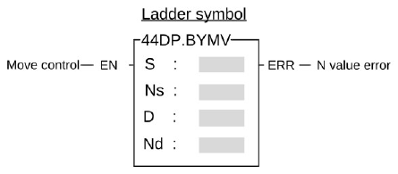
S: Source data to be moved Ns: Assign Ns byte within S as source byte D: Destination register to be moved Nd: Assign Nd byte within D as target byte S, Ns, D, Nd may combine with V, Z, P0~P9 to serve indirect address application |
|||||||||||||||||||||||||||||||||||||||||||||||||||||||||||||||||||||||||||||||||||||||||||||||||
|
||||||||||||||||||||||||||||||||||||||||||||||||||||||||||||||||||||||||||||||||||||||||||||||||||
|
Description |
||||||||||||||||||||||||||||||||||||||||||||||||||||||||||||||||||||||||||||||||||||||||||||||||||
|
||||||||||||||||||||||||||||||||||||||||||||||||||||||||||||||||||||||||||||||||||||||||||||||||||
|
FUN44 D P BYMV |
BYTE MOVE |
FUN44 D P BYMV |
||||||||||||||||||||||||||||||||||||||||||||||||||||||||||||||||||||||||
|
Example |
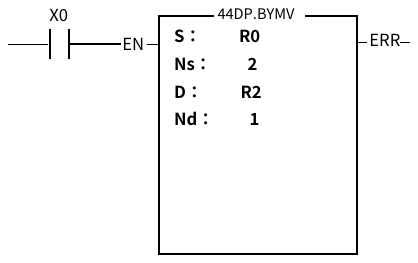
||||||||||||||||||||||||||||||||||||||||||||||||||||||||||||||||||||||||||
B31 B0
Byte3 Byte2 Byte1 Byte0 Ns=2───────────── ⇩X0= Nd=1───────────────────── Byte3 Byte2 Byte1 Byte0
B31 B0 |
||||||||||||||||||||||||||||||||||||||||||||||||||||||||||||||||||||||||||


7-4-6 EXCHANGE (XCHG)
|
FUN45 D P XCHG |
EXCHANGE |
FUN45 D P XCHG |
|||||||||||||||||||||||||||||||||||||||||||||||||||||||||||||||||||||||||
|
Symbol |
|||||||||||||||||||||||||||||||||||||||||||||||||||||||||||||||||||||||||||
|
|
Da: Register a to be exchanged Db: Register b to be exchanged Da, Db may combine with V, Z, P0~P9 to serve indirect address application |
||||||||||||||||||||||||||||||||||||||||||||||||||||||||||||||||||||||||||
|
|||||||||||||||||||||||||||||||||||||||||||||||||||||||||||||||||||||||||||
|
Description |
|||||||||||||||||||||||||||||||||||||||||||||||||||||||||||||||||||||||||||
|
|||||||||||||||||||||||||||||||||||||||||||||||||||||||||||||||||||||||||||
|
Example |
|||||||||||||||||||||||||||||||||||||||||||||||||||||||||||||||||||||||||||
The instruction exchanges the contents of the 16-bit R0 and R1 registers. |
|||||||||||||||||||||||||||||||||||||||||||||||||||||||||||||||||||||||||||
|
FUN45 D P XCHG |
EXCHANGE |
FUN45 D P XCHG |
|||||||||||||||||||||||||||||||||||||||||||||||||||||||||||||||||||||||||
|
B15 B0
⇩X0= B15 B0
|
|||||||||||||||||||||||||||||||||||||||||||||||||||||||||||||||||||||||||||


7-4-7 BYTE SWAP (SWAP)
|
FUN46 P SWAP |
BYTE SWAP |
FUN46 P SWAP |
|||||||||||||||||||||||||||||||||||||||
|
Symbol |
|||||||||||||||||||||||||||||||||||||||||
|
|
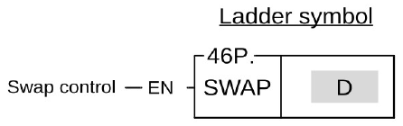
D: Register for byte data swap D may combine with V, Z, P0~P9 to serve indirect address application |
||||||||||||||||||||||||||||||||||||||||
|
|||||||||||||||||||||||||||||||||||||||||
|
Description |
|||||||||||||||||||||||||||||||||||||||||
|
|||||||||||||||||||||||||||||||||||||||||
|
FUN46 P SWAP |
BYTE SWAP |
FUN46 P SWAP |
||||||||||||||||||||||||||||||||||||||||
|
Example |
||||||||||||||||||||||||||||||||||||||||||
The instruction swaps the data of the low byte (B0~B7) and the high byte (B8~B15) in R0. The results are as follows: Byte1 Byte0
B15 B8 B7 B0 ⇩X0= B15 │ B0
|
||||||||||||||||||||||||||||||||||||||||||

7-5 Shifting/Rotating Instructions (FUN51~54)
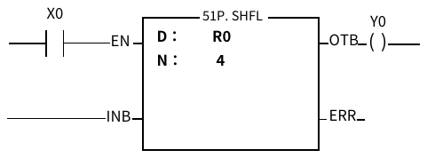
7-5-1 SHIFT LEFT (SHFL)
|
FUN51 D P SHFL |
SHIFT LEFT |
FUN51 D P SHFL |
||||||||||||||||||||||||||||||||||||||||||||||||||||||||||||||||
|
Symbol |
||||||||||||||||||||||||||||||||||||||||||||||||||||||||||||||||||
|
|
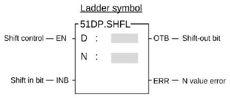
D: Register to be shifted N: Number of bits to be shifted N, D may combine with V, Z, P0~P9 to serve indirect address application |
|||||||||||||||||||||||||||||||||||||||||||||||||||||||||||||||||
|
||||||||||||||||||||||||||||||||||||||||||||||||||||||||||||||||||
|
Description |
||||||||||||||||||||||||||||||||||||||||||||||||||||||||||||||||||
|
||||||||||||||||||||||||||||||||||||||||||||||||||||||||||||||||||
|
FUN51 D P SHFL |
SHIFT LEFT |
FUN51 D P SHFL |
||||||||||||||||||||||||||||||||||||||||||||||||||||||||||||||||||||||||||||||||||||
|
Example |
||||||||||||||||||||||||||||||||||||||||||||||||||||||||||||||||||||||||||||||||||||||
Y0 B15 R0 B0 INB
⇩X0= Y0 B15 R0 B0 INB
|
||||||||||||||||||||||||||||||||||||||||||||||||||||||||||||||||||||||||||||||||||||||
7-5-2 SHIFT RIGHT (SHFR)
|
FUN52 D P SHFR |
SHIFT RIGHT |
FUN52 D P SHFR |
||||||||||||||||||||||||||||||||||||||||||||||||||||||||||||||||
|
Symbol |
||||||||||||||||||||||||||||||||||||||||||||||||||||||||||||||||||
|
|
D: Register to be shifted N: Number of bits to be shifted D, N may combine with V, Z, P0~P9 to serve indirect address application |
|||||||||||||||||||||||||||||||||||||||||||||||||||||||||||||||||
|
||||||||||||||||||||||||||||||||||||||||||||||||||||||||||||||||||
|
Description |
||||||||||||||||||||||||||||||||||||||||||||||||||||||||||||||||||
|
||||||||||||||||||||||||||||||||||||||||||||||||||||||||||||||||||
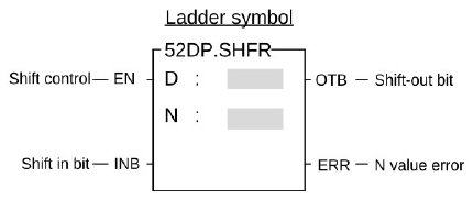
|
FUN52 D P SHFR |
SHIFT RIGHT |
FUN52 D P SHFR |
||||||||||||||||||||||||||||||||||||||||||||||||||||||||||||||||||||||||||||||||||||
|
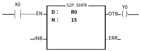
Example |
||||||||||||||||||||||||||||||||||||||||||||||||||||||||||||||||||||||||||||||||||||||
INB B15 R0 B0 Y0
⇩X0= INB B15 R0 B0 Y0
|
||||||||||||||||||||||||||||||||||||||||||||||||||||||||||||||||||||||||||||||||||||||
7-5-3 ROTATE LEFT (ROTL)
|
FUN53 D P ROTL |
ROTATE LEFT |
FUN53 D P ROTL |
|||||||||||||||||||||||||||||||||||||||||||||||||||||||||||||||||
|
Symbol |
|||||||||||||||||||||||||||||||||||||||||||||||||||||||||||||||||||
|
|
D: Register to be rotated N: Number of bits to be rotated D, N may combine with V, Z, P0~P9 to serve indirect address application |
||||||||||||||||||||||||||||||||||||||||||||||||||||||||||||||||||
|
|||||||||||||||||||||||||||||||||||||||||||||||||||||||||||||||||||
|
Description |
|||||||||||||||||||||||||||||||||||||||||||||||||||||||||||||||||||
|
|||||||||||||||||||||||||||||||||||||||||||||||||||||||||||||||||||
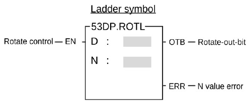
|
FUN53 D P ROTL |
ROTATE LEFT |
FUN53 D P ROTL |
||||||||||||||||||||||||||||||||||||||||||||||||||||||||||||||||||||||||||||||||||||||||||||||||||||||||||||||||||||||||||
|
Example |
||||||||||||||||||||||||||||||||||||||||||||||||||||||||||||||||||||||||||||||||||||||||||||||||||||||||||||||||||||||||||||
R0 B0
⇩X0= B15 R0 B0
|
||||||||||||||||||||||||||||||||||||||||||||||||||||||||||||||||||||||||||||||||||||||||||||||||||||||||||||||||||||||||||||

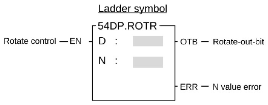
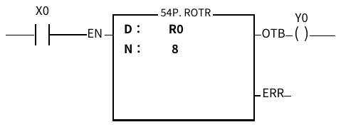
7-5-4 ROTATE RIGHT (ROTR)
|
FUN54 D P ROTR |
ROTATE RIGHT |
FUN54 D P ROTR |
||||||||||||||||||||||||||||||||||||||||||||||||||||||||||||||||
|
Symbol |
||||||||||||||||||||||||||||||||||||||||||||||||||||||||||||||||||
|
|
D: Register to be rotated N: Number of bits to be rotated D, N may combine with V, Z, P0~P9 to serve indirect address application |
|||||||||||||||||||||||||||||||||||||||||||||||||||||||||||||||||
|
||||||||||||||||||||||||||||||||||||||||||||||||||||||||||||||||||
|
Description |
||||||||||||||||||||||||||||||||||||||||||||||||||||||||||||||||||
|
||||||||||||||||||||||||||||||||||||||||||||||||||||||||||||||||||
|
FUN54 D P ROTR |
ROTATE RIGHT |
FUN54 D P ROTR |
||||||||||||||||||||||||||||||||||||||||||||||||||||||||||||||||||||||||||||||||||||||||||||||||||||||||||||||||||||
|
Example |
||||||||||||||||||||||||||||||||||||||||||||||||||||||||||||||||||||||||||||||||||||||||||||||||||||||||||||||||||||||
B15 R0 B0
⇩X0= B15 R0 B0
|
||||||||||||||||||||||||||||||||||||||||||||||||||||||||||||||||||||||||||||||||||||||||||||||||||||||||||||||||||||||
7-6 Code Conversion Instructions (FUN55~64)
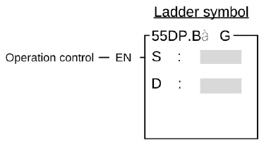
7-6-1 INARY-CODE TO GRAY-CODE CONVERSION (B→G)
|
FUN55 D P B→G |
BINARY-CODE TO GRAY-CODE CONVERSION |
FUN55 D P B→G |
||||||||||||||||||||||||||||||||||||||||||||||||||||||||||||||||
|
Symbol |
||||||||||||||||||||||||||||||||||||||||||||||||||||||||||||||||||
|
|
S: Starting of source D: Starting addr ess of destination S, D operand can combine V, Z, P0~P9 for index addressing |
|||||||||||||||||||||||||||||||||||||||||||||||||||||||||||||||||
|
||||||||||||||||||||||||||||||||||||||||||||||||||||||||||||||||||
|
Description |
||||||||||||||||||||||||||||||||||||||||||||||||||||||||||||||||||
|
||||||||||||||||||||||||||||||||||||||||||||||||||||||||||||||||||
|
FUN55 D P B→G |
BINARY-CODE TO GRAY-CODE CONVERSION |
FUN55 D P B→G |
||||
|
Example1 |
||||||
|
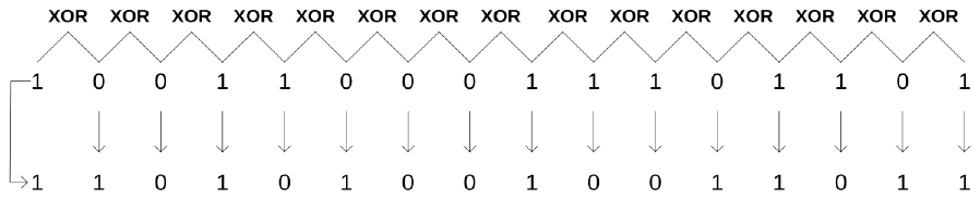
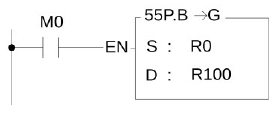
When M0 is from OFF→ON, convert R0 (binary code) into Gray code, and then store it in R100.
R0=1001010101010011B 🡺 R100=1101111111111010B |
||||||
|
Example2 |
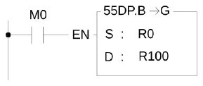
When M0 =1, it will perform the 32-bit code conversion |
|||||
|
When M0 is ON, convert DR0 (binary code) to Gray code, and then store it in DR100.
DR0=00110111001001000010111100010100B 🡺 DR100=00101100101101100011100010011110B |
||||||
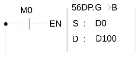
7-6-2 GRAY-CODE TO BINARY-CODE CONVERSION (G→B)
|
FUN56 D P G→B |
GRAY-CODE TO BINARY-CODE CONVERSION |
FUN56 D P G→B |
||||||||||||||||||||||||||||||||||||||||||||||||||||||||||||||||
|
Symbol |
||||||||||||||||||||||||||||||||||||||||||||||||||||||||||||||||||
|
|
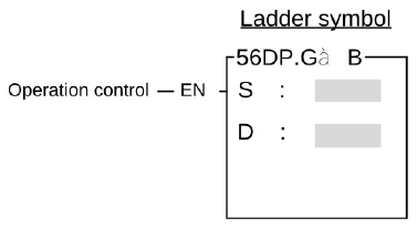
S: Starting of source D: Starting address of destination S, D operand can combine V, Z, P0~P9 for index addressing |
|||||||||||||||||||||||||||||||||||||||||||||||||||||||||||||||||
|
||||||||||||||||||||||||||||||||||||||||||||||||||||||||||||||||||
|
Description |
||||||||||||||||||||||||||||||||||||||||||||||||||||||||||||||||||
|
||||||||||||||||||||||||||||||||||||||||||||||||||||||||||||||||||

|
FUN56 D P G→B |
GRAY-CODE TO BINARY-CODE CONVERSION |
FUN56 D P G→B |
||||
|
Example1 |
||||||
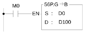
D0=1001010101010011B 🡺D100=1110011001100010B |
||||||
|
Example2 |
When M0 =1, it will perform the 32-bit code conversion |
|||||
|
When M0 is ON, convert DD0 (binary code) to Gray code, and then store it in DD100
DD0=00110111001001000010111100010100B 🡺 DD100=00100101110001111100101000011000B |
||||||
7-6-3 DECODE (DECOD)
|
FUN57 P DECOD |
DECODE |
FUN57 P DECOD |
||||||||||||||||||||||||||||||||||||||||||||||||||||||||||||||||||||||||||||||||||||||||||||||||
|
Symbol |
||||||||||||||||||||||||||||||||||||||||||||||||||||||||||||||||||||||||||||||||||||||||||||||||||
|
|
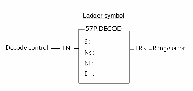
S : Source data register to be decoded (16 bits) NS : Starting bits to be decoded within S NL : Length of decoded value (1~8 bits) D : Starting register storing decoded results (2~256 points = 1~16 words) S, NS, NL, D may combine with V, Z, P0~P9 to serve indirect address application |
|||||||||||||||||||||||||||||||||||||||||||||||||||||||||||||||||||||||||||||||||||||||||||||||||
|
||||||||||||||||||||||||||||||||||||||||||||||||||||||||||||||||||||||||||||||||||||||||||||||||||
|
Description |
||||||||||||||||||||||||||||||||||||||||||||||||||||||||||||||||||||||||||||||||||||||||||||||||||
|
||||||||||||||||||||||||||||||||||||||||||||||||||||||||||||||||||||||||||||||||||||||||||||||||||
7-6-4 ENCODE (ENCOD)
|
FUN58 P ENCOD |
ENCODE |
FUN58 P ENCOD |
||||||||||||||||||||||||||||||||||||||||||||||||||||||||||||||||||||||||||||||||||||||||||||||||
|
Symbol |
||||||||||||||||||||||||||||||||||||||||||||||||||||||||||||||||||||||||||||||||||||||||||||||||||
|
|
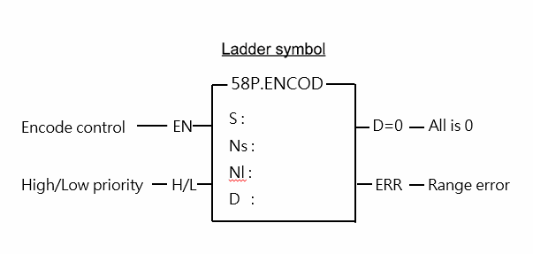
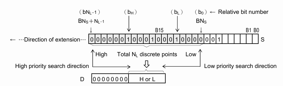
S : Starting register to be encoded NS : Bit position within S as the encoding start point NL : Number of encoding discrete points (2~256) D : Number of register storing encoding results (1 word) S, NS, NL, D may combine with V, Z, P0~P9 to serve indirect address application |
|||||||||||||||||||||||||||||||||||||||||||||||||||||||||||||||||||||||||||||||||||||||||||||||||
|
||||||||||||||||||||||||||||||||||||||||||||||||||||||||||||||||||||||||||||||||||||||||||||||||||
|
Description |
||||||||||||||||||||||||||||||||||||||||||||||||||||||||||||||||||||||||||||||||||||||||||||||||||
|
||||||||||||||||||||||||||||||||||||||||||||||||||||||||||||||||||||||||||||||||||||||||||||||||||
|
FUN58 P ENCOD |
ENCODE |
FUN58 P ENCOD |
|
Description |
||
|
|
||
7-6-5 HOUR:MINUTE:SECOND→SECOND
|
FUN61 P →SEC |
HOUR:MINUTE:SECOND→SECOND |
FUN61 P →SEC |
||||||||||||||||||||||||||||||||||||||||||||||||||||||||
|
Symbol |
||||||||||||||||||||||||||||||||||||||||||||||||||||||||||
|
|
S: Starting calendar data register to be converted D: Starting register storing results |
|||||||||||||||||||||||||||||||||||||||||||||||||||||||||
|
||||||||||||||||||||||||||||||||||||||||||||||||||||||||||
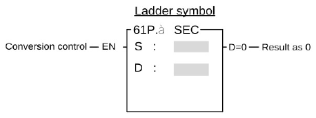
|
FUN61 P →SEC |
HOUR:MINUTE:SECOND→SECOND |
FUN61 P →SEC |
|||||||||||||||||||||||||
|
Description |
|||||||||||||||||||||||||||
B15 B14 B0 B15B0
↑B31 is used to represent the positive or The B15 of each register is used to represent the sign of each time value negative nature of the sec. value
|
|||||||||||||||||||||||||||
|
FUN61 P →SEC |
HOUR:MINUTE:SECOND→SECOND |
FUN61 P →SEC |
|||||||||||||||||||||||||||
|
Example |
|||||||||||||||||||||||||||||
|
|||||||||||||||||||||||||||||
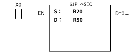
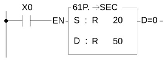
7-6-6 SECOND→HOUR:MINUTE:SECOND
|
FUN62 P →HMS |
SECOND→HOUR:MINUTE:SECOND |
FUN62 P →HMS |
||||||||||||||||||||||||||||||||||||||||||||||||||||||||||||
|
Symbol |
||||||||||||||||||||||||||||||||||||||||||||||||||||||||||||||
|
|
S: Starting register of second to be converted D: Starting register storing result of conversion (hour : minute : second) |
|||||||||||||||||||||||||||||||||||||||||||||||||||||||||||||
|
||||||||||||||||||||||||||||||||||||||||||||||||||||||||||||||
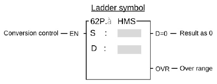
|
FUN62 P →HMS |
SECOND→HOUR:MINUTE:SECOND |
FUN62 P →HMS |
|||||||||||||||||||||||||||||||||||||||||||
|
Description |
|||||||||||||||||||||||||||||||||||||||||||||
|
|||||||||||||||||||||||||||||||||||||||||||||
|
FUN62 P →HMS |
SECOND→HOUR:MINUTE:SECOND |
FUN62 P →HMS |
|||||||||||||||||||||
|
Example |
|||||||||||||||||||||||
|
|||||||||||||||||||||||
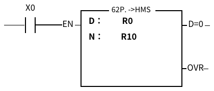
7-6-7 CONVERSION OF ASCII CODE TO HEXADECIMAL VALUE (ASCII→HEX)
|
FUN63 P →HEX |
CONVERSION OF ASCII CODE TO HEXADECIMAL VALUE |
FUN63 P →HEX |
||||||||||||||||||||||||||||||||||||||||||||||||||||||||||||||||||||||||||||||||
|
Symbol |
||||||||||||||||||||||||||||||||||||||||||||||||||||||||||||||||||||||||||||||||||
|
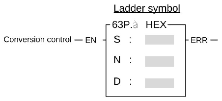
|
S: Starting source register. N: Number of ASCII codes to be converted to hexadecimal values. D: The starting register that stores the result (hexadecimal value). S, N, D, can associate with V, Z, P0~P9 to do the indirect addressing application. |
|||||||||||||||||||||||||||||||||||||||||||||||||||||||||||||||||||||||||||||||||
|
||||||||||||||||||||||||||||||||||||||||||||||||||||||||||||||||||||||||||||||||||
|
Description |
||||||||||||||||||||||||||||||||||||||||||||||||||||||||||||||||||||||||||||||||||
|
||||||||||||||||||||||||||||||||||||||||||||||||||||||||||||||||||||||||||||||||||
|
FUN63 P →HEX |
CONVERSION OF ASCII CODE TO HEXADECIMAL VALUE |
FUN63 P →HEX |
||||
|
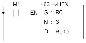
Example1 |
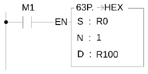
When M1 from OFF→ON, ASCII code converted to hexadecimal value. |
|||||
Originally R100=0000H R0=0039H(9)🡺 R100=0009H |
||||||
|
Example2 |
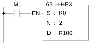
When M1 is ON, ASCII code converted to hexadecimal value. |
|||||
R0=0039H(9) Originally R100=0000H R1=0041H(A)🡺 R100=009AH |
||||||
|
Example3 |
|||||
R0=0039H (9) Originally R100=0000H R1=0041H (A) R2=0045H (E)🡺 R100=09AEH |
|||||
|
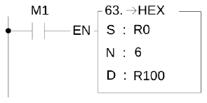
Example4 |
When M1 is ON, ASCII code converted to hexadecimal value |
||||
R0=0031H(1) Originally R100=0000H R1=0032H(2) R101=0000H R2=0033H(3) R3=0034H(4) R4=0035H(5)🡺 R100=3456H R5=0036H(6) R101=0012H |
|||||
7-6-8 CONVERSION OF HEXADECIMAL VALUE TO ASCII CODE (HEX→ASCII)
|
FUN64 P →ASCII |
CONVERSION OF HEXADECIMAL VALUE TO ASCII CODE |
FUN64 P →ASCII |
||||||||||||||||||||||||||||||||||||||||||||||||||||||||||||||||||||||||||||||||
|
Symbol |
||||||||||||||||||||||||||||||||||||||||||||||||||||||||||||||||||||||||||||||||||
|
|
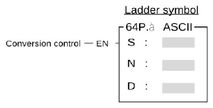
S: Starting source register N: Number of hexadecimal digits to be converted to ASCII code. D: The starting register storing result. S, N, D, can associate with V, Z, P0~P9 to do the indirect addressing application. |
|||||||||||||||||||||||||||||||||||||||||||||||||||||||||||||||||||||||||||||||||
|
||||||||||||||||||||||||||||||||||||||||||||||||||||||||||||||||||||||||||||||||||
|
Description |
||||||||||||||||||||||||||||||||||||||||||||||||||||||||||||||||||||||||||||||||||
|
||||||||||||||||||||||||||||||||||||||||||||||||||||||||||||||||||||||||||||||||||
|
FUN64 P →ASCII |
CONVERSION OF HEXADECIMAL VALUE TO ASCII CODE |
FUN64 P →ASCII |
||||
|
Example1 |
||||||
R0=0009H 🡺 R100=0039H(9) |
||||||
|
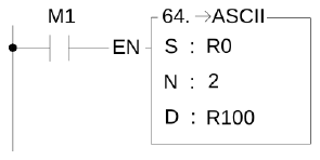
Example2 |
When M1 is ON, it converts hexadecimal value to ASCII code. |
|||||
R0=009AH 🡺 R100=0039H(9) R101=0041H(A) |
||||||

|
FUN64 P →ASCII |
CONVERSION OF HEXADECIMAL VALUE TO ASCII CODE |
FUN64 P →ASCII |
||||
|
Example3 |
When M1 is ON, it converts hexadecimal value to ASCII code. |
|||||
R0=0123H 🡺 R100=0031H(1) R101=0032H(2) R102=0033H(3) |
||||||

|
FUN64 P →ASCII |
CONVERSION OF HEXADECIMAL VALUE TO ASCII CODE |
FUN64 P →ASCII |
||||
|
Example4 |
When M1 is ON, it converts hexadecimal value to ASCII code. |
|||||
R0=3456H 🡺 R100=0031H(1) R1=0012H R101=0032H(2) R102=0033H(3) R103=0034H(4) R104=0035H(5) R105=0036H(6) |
||||||

7-7 Flow Control Instructions II (FUN22、FUN65~71)
7-7-1 Break
|
FUN22 P BREAK |
BREAK FROM FOR AND NEXT LOOP (BREAK) |
FUN22 P BREAK |
|
Symbol |
||
|
|
||
|
Description |
||
|
||

|
FUN22 P BREAK |
BREAK FROM FOR AND NEXT LOOP (BREAK) |
FUN22 P BREAK |
||||
|
Example |
||||||
Description:The loop count used to execute the FOR and NEXT program loop is assigned by register D10; the program within the FOR and NEXT loop is designed to search the same data storing in D100 from the register table starting at R0. If it finds, the searching loop will be terminated and then it goes to execute the program after the NEXT instruction. If it doesn’t find, the searching loop will be executed N times (N is the content of D10) and then it goes to execute the program after the NEXT instruction. M200 tells the status and D100 is the pointer of searching. |
||||||

7-7-2 LABEL (LBL)
|
FUN65 LBL |
LABEL |
FUN65 LBL |
|||||||
|
Symbol |
|||||||||
|
|
S: Alphanumeric, 1~6 characters |
|
|||||||
|
Description |
※Only supported in the main program and subroutine |
||||||||
|
|||||||||

|
FUN65 LBL |
LABEL |
FUN65 LBL |
||||||||||
Unless the program you marked is indeed the service program corresponding to the above interrupt, the above name can be used, and it cannot be used elsewhere. Otherwise, when an interrupt occurs, the PLC will execute the general program you marked as an interrupt program, resulting in errors or crash. |
||||||||||||
|
FUN65 LBL |
LABEL |
FUN65 LBL |
||||
|
Example |
||||||
|
The label of following diagram illustration served only as program remarks (it is not treated as a label for call or jump target). For the application of labeling in jump control, please refer to JMP instruction for explanation. As to the labeling serves as subroutine names, please refer to CALL instruction for details.
|
||||||

7-7-3 JUMP (JMP)
|
FUN66 P JMP |
JUMP |
FUN66 P JMP |
|||||||
|
Symbol |
|||||||||
|
|
LBL: The program label to be jumped |
|
|||||||
|
Description |
|||||||||
|
|||||||||
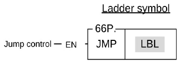
|
FUN66 P JMP |
JUMP |
FUN66 P JMP |
||||
|
Example |
||||||
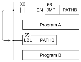
In this diagram, when X0=1, the program will jump directly to the LBL position named PATHB and continuing to execute program B. Therefore, it will skip the program A and none of the instructions of program A will be executed. The status of registers and the coils associated with program A will keep unchanged (as if there is no program section A). |
||||||
7-7-4 FUNCTION BLOCK LABEL
|
FUN165 FLBL |
FUNCTION BLOCK LABEL |
FUN165 FLBL |
|||||||
|
Symbol |
|||||||||
|
|
S: English/ Digit 1~6 |
|
|||||||
|
Discription |
※It only supported in the function block diagram. |
||||||||
|
|||||||||

|
FUN165 FLBL |
FUNCTION BLOCK LABEL |
FUN165 FLBL |
||||||||||
Unless the program you labeled is indeed the service program corresponding to the above interrupts, the above labels can be used and cannot be used elsewhere. Otherwise, the PLC will execute the general program you labeled as an interrupt program when an interrupt occurs, resulting in errors or crashes. |
||||||||||||
|
FUN165 FLBL |
FUNCTION BLOCK LABEL |
FUN165 FLBL |
||||
|
Example |
||||||
|
The illustration below is an example of a label only used as a program comment (not called or jumped to this mark). As for applying the label in jump control, please refer to the description of the JMP instruction. Please refer to the order’s CALL Description when the label is a subroutine name.
|
||||||

7-7-5 FUNCTION BLOCK JUMP
|
FUN166 P FJMP |
FUNCTION BLOCK JUMP |
FUN166 P FJMP |
|||||||
|
Symbol |
|||||||||
|
|
FLBL:The program label to be jumped |
|
|||||||
|
Discription |
※It’s only supported in the function block diagram. |
||||||||
|
|||||||||

|
FUN166 P FJMP |
FUNCTION BLOCK JUMP |
FUN166 P FJMP |
||||
|
Example |
||||||
In the figure above, when X0=1, the execution will jump directly from where the JMP command is located to the site where the FLBL name is PATHB so that program A is skipped and all instructions in A are not executed. The list related to program A Points or register status remains unchanged (as if there is no A program). |
||||||

7-7-6 CALL
|
FUN67 P CALL |
CALL |
FUN67 P CALL |
|||||||
|
Symbol |
|||||||||
|
|
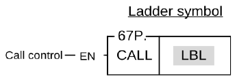
LBL: The subroutine label name to be called. |
|
|||||||
|
Description |
|||||||||
|
|||||||||

|
FUN67 P CALL |
CALL |
FUN67 P CALL |
|
||

7-7-7 RETURN FROM SUBROUTINE (RTS)
|
FUN68 RTS |
RETURN FROM SUBROUTINE |
FUN68 RTS |
|
Symbol |
||
|
|
||
|
Description |
||
|
||
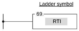
7-7-8 RETURN FROM INTERRUPT (RTI)
|
FUN69 RTI |
RETURN FROM INTERRUPT |
FUN69 RTI |
|
Symbol |
||
|
|
||
|
Description |
||
|
||
|
FUN69 RTI |
RETURN FROM INTERRUPT |
FUN69 RTI |
|
Description |
||
|
||
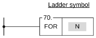
7-7-9 FOR
|
FUN70 FOR |
FOR |
FUN70 FOR |
|||||||||||||||||||||||||||||||||||||||||||||
|
Symbol |
|||||||||||||||||||||||||||||||||||||||||||||||
|
|
N: Number of times of loop execution |
||||||||||||||||||||||||||||||||||||||||||||||
|
|||||||||||||||||||||||||||||||||||||||||||||||
|
Description |
|||||||||||||||||||||||||||||||||||||||||||||||
|
|||||||||||||||||||||||||||||||||||||||||||||||
|
FUN70 FOR |
FOR |
FUN70 FOR |
||||
|
Example |
||||||
|
||||||
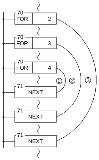
 will be executed 4 ×3 ×2 = 24 times, loop
 will be executed 3 ×2 = 6 times, and loop
 will be executed 2 times.
7-7-10 NEXT
|
FUN71 NEXT |
LOOP END |
FUN71 NEXT |
|
Symbol |
||
|
|
||
|
Description |
||
|
||

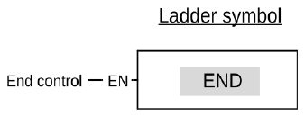
7-7-11 PROGRAM END
|
END |
PROGRAM END |
END |
|
|
Symbol |
|||
|
|
No operand |
||
|
Description |
|||
|
|||
|
END |
PROGRAM END |
END |
|
Example |
||
|
|
||
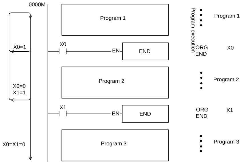
7-8 I/O Instructions (FUN74~86)
7-8-1 IMMEDIATE I/O REFRESH (IMDIO)
|
FUN74 P IMDIO |
IMMEDIATE I/O REFRESH |
FUN74 P IMDIO |
||||||||||||||||
|
Symbol |
||||||||||||||||||
|
|
D: The starting address of the I/O point to be updated N: The number of I/O points to be updated |
|||||||||||||||||
|
||||||||||||||||||
|
Description |
||||||||||||||||||
|
||||||||||||||||||

|
FUN74 P IMDIO |
IMMEDIATE I/O REFRESH |
FUN74 P IMDIO |
||||||||||||
|
||||||||||||||
7-9 PID Control (FUN30,FUN38, FUN99)
7-9-1 General PID operation (Main Unit)
|
FUN30 PID |
General PID operation |
FUN30 PID |
|||||||||||||||||||||||||||||||||||
|
Symbol |
|||||||||||||||||||||||||||||||||||||
|
|
Ts:Solution interval between calculations SR:Starting register of loop settings ; OR:Output register of PID loop operation. PR:Starting register of loop parameters; WR:Staring register of working registers for this instruction ,it takes 5 registers and can’t be repeated in using. |
||||||||||||||||||||||||||||||||||||
|
|||||||||||||||||||||||||||||||||||||
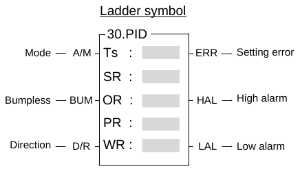
|
FUN30 PID |
PID |
FUN30 PID |
|
Description |
||
Mn : Control output at "n" time Mn R35765 :The gain constant, the default is 1000, which can be set between 1~5000. Pb :Proportional band The expression stating the percent change in error required to change the output full scale. ( Range:1~5000,unit in 0.1%;Kc(gain)=R35765/P ) Ki : Integral tuning constant(range:0~9999,it means 0.00~99.99 Repeats/Minute) Td : Derivative tuning constant(range:0~3600,equivalent to 0~3600 Seconds) : Process variable at time "n" :Process variable when loop was last solved En : The difference between the set point (SP) and the process variable (PV) at time "n". En = SP – . Ts : Solution interval between calculations(Range:1~3000, unit in 0.01S) Bias : Offset to the output(Range:0~16383) |
||
|
FUN30 PID |
PID |
FUN30 PID |
|
|
|||
|
FUN30 PID |
PID |
FUN30 PID |
|
|
|||
|
FUN30 PID |
PID |
FUN30 PID |
|
||
|
FUN30 PID |
PID |
FUN30 PID |
(This is because the equation uses R35765 divided by Pb.) It must be the range:1 ≦ Pb ≦5000, unit is in 0.1%. Kc(gain)=R35765/ Pb; the default of R35765 is 1000, and it’s range is 1 ≦ R35765 ≦ 5000.
It must be the range:0 ≦ Ki ≦ 9999 (0.00~99.99 Repeats/Minute)
It must be the range:0 ≦ Td ≦ 9999 (0.00~99.99 Minutes) |
||
|
FUN30 PID |
PID |
FUN30 PID |
It must be the range:0 ≦ Bias ≦ 16383
It must be the range:1 ≦ HIWL ≦ 16383
It must be the range:0 ≦ LIWL ≦ 16383
=0 , Standard PID method; =1 , Minimum Overshoot Method; Method 0 is prefer because most applications using PI control (Td=0). The user may try method 1 when using PID control and the result is not stable.
|
||
|
FUN30 PID |
PID |
FUN30 PID |
Bit0 =0 , Manual operation mode =1 , Auto mode Bit1 : This bit will be a 1 during the scan the solution is being solved, and it is ON for a scan time. Bit2=1 , Bumpless transfer Bit4 : The status of "ERR" indication Bit5 : The status of "HAL" indication Bit6 : The status of "LAL" indication
|
||
|
FUN30 PID |
PID |
FUN30 PID |
|
|
|||

|
FUN30 PID |
PID |
FUN30 PID |
|
|
R999 :The setting of solution interval between calculations; for example the content of R999 is 200, it means it will perform this PID operation every 2 seconds. R1000 :Scaled process variable, which is the engineering unit loaded by the PID instruction every time it gets solved. A linear scaling is done on R1006 using the high and low engineering range found in R1004 and R1005. R1001 :Setpoint, it is the desired value the loop should control at; which is entered in engineering unit. For example the span of controlling process is 0°C~500°C, the setting of R1001 is equal to 100, it means the desired result is at 100°C. R1002 :The setting of high alarm limit; which is entered in engineering unit. R1003 :The setting of low alarm limit; which is entered in engineering unit. The example mentioned, if the setting of R1003 is equal to 95, it means there will have the low alarm while the loop is less than or equal to 95°C. R1004 :The setting of high engineering range. The example mentioned, if the setting of R1004 is equal to 500, it means the highest value of this loop is 500°C. R1005 :The setting of low engineering range. The example mentioned, if the setting of R1005 is equal to 0, it means the lowest value of this loop is 0°C. R1006 :Raw analog measurement; it is the value that the content of analog input register (R34768〜R34895) is added by the offset of 2048. R1007:Offset of process variable; let it be 0 if the raw analog signal and the span of the analog input module are all 0〜10V. |
R1020 :The setting of proportional band; for example the content of R1020 is 20, R1021 :The setting of integral tuning constant; R1022 :The setting of derivative tuning constant; for example the content of R1022 is 0, it means PI control. R1023 :The setting of the bias to the output; R1024 :The setting of high integral wind-up; R1025 :The setting of low integral wind-up; R1026 :The setting of PID method; R1030 = Loop status register Bit0 =0, Manual operation mode Bit1 : This bit will be a 1 during the scan the solution is being solved, and it is ON for Bit2=1 , Bumpless transfer Bit4 : The status of "ERR" indication Bit5 : The status of "HAL" indication Bit6 : The status of "LAL" indication R1031~R1034: They are the working registers, please refer to the description of operand WR. |
||
7-9-2 General-Purpose PID 2 Instruction
|
FUN38 PID2 |
PID 2 |
FUN38 PID2 |
||||||||||||||||||||||||||||||||||||||||||||||||
|
Symbol |
||||||||||||||||||||||||||||||||||||||||||||||||||
|
|
ID: The number of the expansion module used as the input signal CH: Channel number for input signal SR: Program-controlled setting value starting register number, a total of 8 registers are occupied OR: PID output register number PR: The starting register number of the parameter setting value, a total of 7 registers are occupied WR: The starting number of the working register used by this command, occupying 5 registers in total, and other places cannot be reused. |
|||||||||||||||||||||||||||||||||||||||||||||||||
|
||||||||||||||||||||||||||||||||||||||||||||||||||
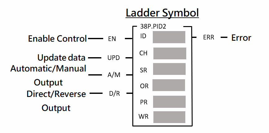
|
FUN38 PID2 |
PID 2 |
FUN38 PID2 |
|
Description |
||
Mn = [KpxEn]- [KpxTdx(PVn-PVn-1)/Ts] + Bias Mn = : Control output at "n" time Kp :Proportional term real number(range:±(1.8*10-38~3.4*1038)) Ti : Integral time constant(range:0~3600,equivalent to 0~3600 Repeats/Seconds) Td : Differential time constant(range:0~3600,equivalent to 0~3600 Seconds) PVn : Program-controlled variable value at "n" time PV n-1 : "n" last programmed variable value En : Error at "n" time = set value (SP) – program variable value at "n" time (PVn) Ts : Interval time between PID operations (range: 1~300, unit: 0.1S) Bias : Bias output (range: ± (1.8*10-38~3.4*1038) |
||
|
FUN38 PID2 |
PID 2 |
FUN38 PID2 |
For more details of information, please refer to the function and application user manual. |
||
7-9-3 PID Temperature Control Instruction 2 (TPCTL 2)
|
FUN99 P TPCTL2 |
PID TEMPERATURE CONTROL INSTRUCTION 2 |
FUN99 P TPCTL2 |
||||||||||||||||||||||||||||||||||||||||||||||||
|
Symbol |
||||||||||||||||||||||||||||||||||||||||||||||||||
|
|
ID: The number of the expansion module to perform temperature control CH: Expansion module channel that performs temperature control SR: Program-controlled setting start register RP: Gain setting start register OR: Output start register WR: Work start register |
|||||||||||||||||||||||||||||||||||||||||||||||||
|
||||||||||||||||||||||||||||||||||||||||||||||||||
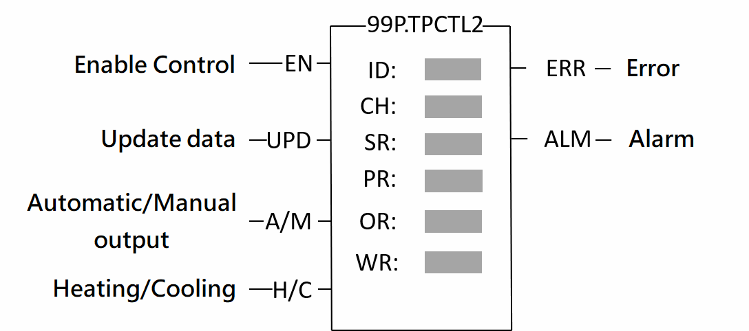
|
FUN99 P TPCTL2 |
PID TEMPERATURE CONTROL INSTRUCTION 2 |
FUN99 P TPCTL2 |
|
Discription |
||
For more details of information, please refer to the function and application user manual. |
||
7-10 Cumulateive Timer Instruction (FUN87~89)
7-10-1 ACCUMULATIVE TIMER (10ms, 100ms, 1s)
|
FUN87 T.01S FUN88 T.1S FUN89 T1S |
ACCUMULATIVE TIMER (0.01s, 0.1s, 1s) |
FUN87 T.01S FUN88 T.1S FUN89 T1S |
||||||||||||||||||||||||||||||||||||||||||||||||||||||||
|
Symbol |
||||||||||||||||||||||||||||||||||||||||||||||||||||||||||
|
|
CV : Register storing elapse time (current value) PV : Preset value of timer |
|||||||||||||||||||||||||||||||||||||||||||||||||||||||||
|
||||||||||||||||||||||||||||||||||||||||||||||||||||||||||
|
Description |
||||||||||||||||||||||||||||||||||||||||||||||||||||||||||
|
||||||||||||||||||||||||||||||||||||||||||||||||||||||||||

|
FUN87 T.01S FUN88 T.1S FUN89 T1S |
ACCUMULATIVE TIMER |
FUN87 T.01S FUN88 T.1S FUN89 T1S |
||||
|
Example 1 |
ON DELAY DE-ENERGIZING Timer |
|||||
|
||||||
|
Example 2 |
ON DELAY DE-ENERGIZING Timer |
|||||
|
||||||
|
Example 3 |
OFF DELAY ENERGIZING Timer |
|||||
|
||||||
|
Example 4 |
OFF DELAY ENERGIZING Timer |
|||||
|
||||||
|
FUN87 T.01S FUN88 T.1S FUN89 T1S |
ACCUMULATIVE TIMER |
FUN87 T.01S FUN88 T.1S FUN89 T1S |
||||
|
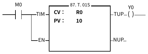
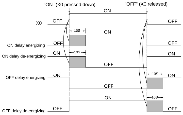
The diagram below shows the relation on input and output for the above 4 kinds of timers.
|
||||||


7-11 Watchdog Timer Instructions (FUN90~91)
7-11-1 Watchdog Timer (WDT)
|
FUN90 P WDT |
WATCHDOG TIMER |
FUN90 P WDT |
|
|
Symbol |
|||
|
|
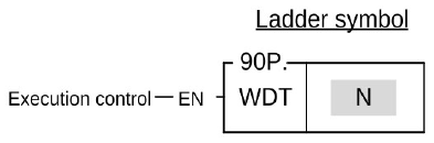
N: The watchdog time. Its value can only be 50, 60, 70…990, The unit is 10MS, that is, the set time range is (50~990) x10MS, that is, 0.05 seconds to 9.9 seconds. |
||
|
Description |
|||
|
|||
7-11-2 RESET WATCHDOG TIMER (RSWDT)
|
FUN91 P RSWDT |
RESET WATCHDOG TIMER |
FUN91 P RSWDT |
|
|
Symbol |
|||
|
|
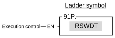
This instruction has no operand. |
||
|
Description |
|||
|
|||
7-12 High Counting/Timing Instruction (FUN92~93)
7-12-1 Hareware High Speed Counter Current Value Access
|
FUN92D P HSCTR |
Hareware High Speed Counter Current Value (CV) Access |
FUN92D P HSCTR |
|
|
Symbol |
|||
|
|
CN:Hardware high speed counter number 0:HSC0 1:HSC1 2:HSC2 3:HSC3 4:HSC4 5:HSC5 6:HSC6 7:HSC7 |
||
|
Description |
|||
|
|||
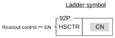
|
FUN92D P HSCTR |
Hareware High Speed Counter Current Value (CV) Access |
FUN92D P HSCTR |
|||||||||||||||||||||||||||||||||||||||||||||||||||||||||||||||||||||||||||||||||||||||||||||||||||||||||||||||||||||||||||||||||||||||||||||||||||||||||
|
|||||||||||||||||||||||||||||||||||||||||||||||||||||||||||||||||||||||||||||||||||||||||||||||||||||||||||||||||||||||||||||||||||||||||||||||||||||||||||
7-12-2 Hardware High Speed Counter Current Value and Preset Value Writing
|
FUN93D P HSCTW |
Hardware High Speed Counter Current Value and Preset Value Writing |
FUN93D P HSCTW |
|
|
Symbol |
|||
|
|
CN:Hardware high speed counter to be written 0:HSC0 1:HSC1 2:HSC2 3:HSC3 4:HST4 5:HSC5 6:HSC6 7:HST7 D: Write target (0 represents CV, 1 r epresents PV) |
||

|
FUN93D P HSCTW |
Hardware High Speed Counter Current Value and Preset Value Writing |
FUN93D P HSCTW |
|
Description |
||
|
● Please refer to FUN92 for the relationship between the CV or PV values of HSC0~HSC3 in the ASIC and the corresponding CV registers and PV registers inside the PLC. ● When the writing control "EN"=1 or from 0→1 (P command), write the contents of the CV register or PV register of the high-speed counter designated by the PLC internal CN to the ASIC correspondingly CV or PV of HSC. ● General applications often need to write PV, that is, write your preset set value to the PV in ASIC. When the count value reaches your set value, the counter will immediately send an interrupt. Through the interrupt service program, you It can be used for various precise counting or positioning control.
|
||
|
FUN93D P HSCTW |
Hardware High Speed Counter Current Value and Preset Value Writing |
FUN93D P HSCTW |
||||
|
Example |
||||||
|
||||||
|
As the program in this diagram, when M0 changes from 0→1, it clears the current value of HSC0 to 0, and writes into ASIC hardware through FUN93.
|
||||||
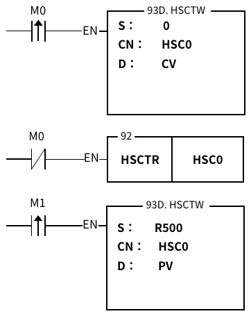
7-13 Slow Up/Slow Down (FUN95~98)
7-13-1 TRACKING TYPE RAMP FUNCTION FOR D/A OUTPUT
|
FUN98 RAMP2 |
TRACKING TYPE RAMP FUNCTION FOR D/A OUTPUT |
FUN98 RAMP2 |
||||||||||||||||||||||||||||||||||||||||||||||||
|
Symbol |
||||||||||||||||||||||||||||||||||||||||||||||||||
|
OM: Maximum output; range from 0~65535 TA: The acceleration time for the output, from 0 up to maximum; Range from 0~65000, unit is in mS. TD: The deceleration time for the output, from maximum down to 0; Range from 0~65000, unit is in mS. RT: Register of target output; Range from 0~65535 RC: Register of current output, it is used for analog output WR: Starting address of working registers, it needs 4 registers |
|||||||||||||||||||||||||||||||||||||||||||||||||
|
||||||||||||||||||||||||||||||||||||||||||||||||||
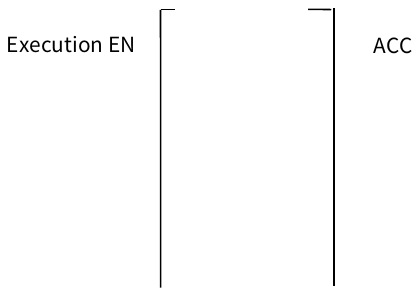 98.RAMP2
 Ta :
|
FUN98 RAMP2 |
TRACKING TYPE RAMP FUNCTION FOR D/A OUTPUT |
FUN98 RAMP2 |
|
Description |
||
|
● When execution 〝EN〞=0, current output value (Rc) will be 0 immediately; the output indicators ACC=0 and DEC=0. ● When execution 〝EN〞=1, this instruction being executed; it will output current value (Rc) first, and then compare the target output value (Rt) with current output value (Rc) every scan; if the target output value is greater than current output value, the current output will be increased according to the rate, which is decided by the settings of acceleration time (Ta) and maximum output (Om), till current output value is equal to the target output value (ACC=1 during this time); if the target output value is less than current output value, the current output will be decreased according to the rate, which is decided by the settings of deceleration time (Td) and maximum output (Om), till current output value is equal to the target output value (DEC=1 during this time). ● If the setting value of target output (Rt) is greater than maximum output(Om), the output value will be clamped by the maximum value. ● It can have smooth activity for acceleration and deceleration control via the execution of this instruction by using current output value (Rc) for analog output (R35024~R35151).。 ● The setting value of target output (Rt) needs to stay two scan times at least for proper operation. ● It needs 4 registers for working, they can not be repeated in use. ● This instruction is for positive value operation, but it also can have negative output by short and easy application program for help. Please see example 2. |
||
|
FUN98 RAMP2 |
TRACKING TYPE RAMP FUNCTION FOR D/A OUTPUT |
FUN98 RAMP2 |
||||
|
Example 1 |
Positive output for ACC/DEC control |
|||||
|
||||||
|
D10: Setting of maximum output, it is 16383 D0: The acceleration time for the output from 0 up to maximum, it is 30000mS D1: The deceleration time for the output from maximum down to 0, it is 20000mS D100: Setting of target output value, it is 8192 R35024: Register of current output, it is used for D/A output D1000~D1003: Working registers Description: When M0=0, current output value is 0 immediately (No ramp). When M0=1, it will output the value of R35024 first; and then compare the target output value (D100) with current output value (R35024) every scan; if D100>R35024, the current output value of R35024 will be increased according to the rate of 16383/30000 (Om=16383, Ta=30000), till R35024=D100 (ACC=1 during this time); if D100<R35024, the current output value of R3904 will be decreased according to the rate of 16383/20000 (Om=16383, Td=20000), till R35024=D100 (DEC=1 during this time).
|
||||||

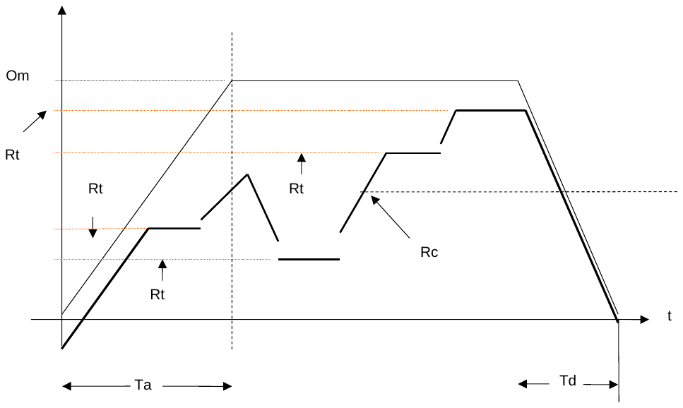
|
FUN98 RAMP2 |
TRACKING TYPE RAMP FUNCTION FOR D/A OUTPUT |
FUN98 RAMP2 |
||||
|
Example 2 |
Both positive and negative output for ACC/DEC control |
|||||
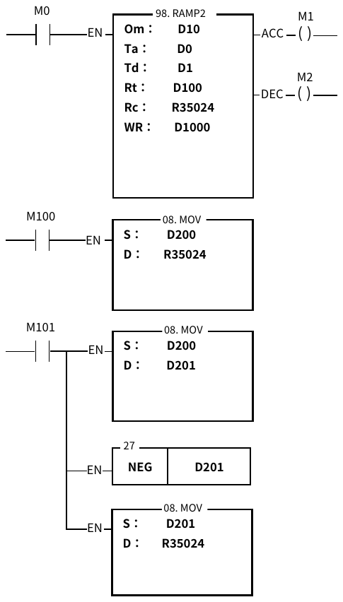
D10 :Setting of maximum output, it is 8191 D0 :The acceleration time for the output from 0 up to maximum, it is 20000mS D1 :The deceleration time for the output from maximum down to 0, it is 10000mS D100:Setting of target output value, it is 0 D200:Register of current output, it is used for analog output D1000~D1003:Working registers |
||||||
|
FUN98 RAMP2 |
TRACKING TYPE RAMP FUNCTION FOR D/A OUTPUT |
FUN98 RAMP2 |
|
Description: Description: When M0=0, current output value is 0 immediately (No ramp). When M0=1, it will output the value of D200 first; and then compare the target output value (D100) with current output value (D200) every scan; if D100>D200, the current output value of D200 will be increased according to the rate of 8191/20000 (Om=8191, Ta=20000), till D200=D100 (ACC=1 during this time); if D100<D200, the current output value of D200 will be decreased according to the rate of 8191/10000 (Om=8191, Td=10000), till D200=D100 (DEC=1 during this time). M100=1, positive output control; M101=1, negative output control. The target output (D100) is always positive value from 0~65535.
|
||

Table Instructions
100. R→T 107. T_FIL
101. T→R 108. T_SHF
102. T→T 109. T_ROT
103. BT_M 110. QUEUE
104. T_SWP 111. STACK
105. R-T_S 112. BKCMP
106. T-T_C
- A table consists of 2 or more consecutive registers (16 or 32 bits). The number of registers that comprise the table is called the table length (L). The operation object of the table instructions always takes the register as unit (i.e. 16 or 32 bit data).
- The operation of table instructions are used mostly for data processing such as move, copy, compare, search etc, between tables and registers, or between tables. These instructions are convenient for application.
- Among the table instructions, most instructions use a pointer to specify which register within a table will be the target of operation. The pointer for both 16 and 32-bit table instructions will always be a 16-bit register. The effective range of the pointer is 0 to L-1, which corresponds to registers T0 to TL-1 (a total of L registers). The table shown below is a schematic diagram for 16-bit and 32-bit tables.
- Among the table operations, shift left/right, rotate left/right operations include a movement direction. The direction toward the higher register is called left, while the direction toward the lower register is called right, as shown in the diagram below.

7-14 Table Instruction (FUN100~114)
7-14-1 REGISTER TO TABLE MOVE
|
FUN100 D P R→T |
REGISTER TO TABLE MOVE |
FUN100 D P R→T |
||||||||||||||||||||||||||||||||||||||||||||||||||||||||||||||||||||||||||||||||||||||||||||||||
|
Symbol |
||||||||||||||||||||||||||||||||||||||||||||||||||||||||||||||||||||||||||||||||||||||||||||||||||
|
|
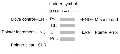
Rs : Source data , can be constant or register Td : Source register for destination table L : Length of destination table Pr : Pointer register Rs, Td can associate with V, Z, P0~P9 index register as indirect addressing |
|||||||||||||||||||||||||||||||||||||||||||||||||||||||||||||||||||||||||||||||||||||||||||||||||
|
||||||||||||||||||||||||||||||||||||||||||||||||||||||||||||||||||||||||||||||||||||||||||||||||||
|
Description |
||||||||||||||||||||||||||||||||||||||||||||||||||||||||||||||||||||||||||||||||||||||||||||||||||
|
||||||||||||||||||||||||||||||||||||||||||||||||||||||||||||||||||||||||||||||||||||||||||||||||||
|
FUN100 D P R→T |
REGISTER TO TABLE MOVE |
FUN100 D P R→T |
||||||||||||||||||||||||||||||||||||||||||||||||||||||||||||||||||||||||||||||||||||||||||||||||||||||||||||||||||||||||||||||||||
|
||||||||||||||||||||||||||||||||||||||||||||||||||||||||||||||||||||||||||||||||||||||||||||||||||||||||||||||||||||||||||||||||||||
|
Example |
||||||||||||||||||||||||||||||||||||||||||||||||||||||||||||||||||||||||||||||||||||||||||||||||||||||||||||||||||||||||||||||||||||
|
||||||||||||||||||||||||||||||||||||||||||||||||||||||||||||||||||||||||||||||||||||||||||||||||||||||||||||||||||||||||||||||||||||


7-14-2 TABLE TO REGISTER MOVE
|
FUN101 D P T→R |
TABLE TO REGISTER MOVE |
FUN101 D P T→R |
||||||||||||||||||||||||||||||||||||||||||||||||||||||||||||||||||||||||||||||||||||||||||||||||
|
Symbol |
||||||||||||||||||||||||||||||||||||||||||||||||||||||||||||||||||||||||||||||||||||||||||||||||||
|
|
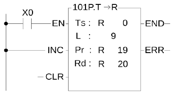
Ts : Source table starting register L : Length of source table Pr : Pointer register Rd : Destination register Ts, Rd may combine with V, Z, P0~P9 to serve indirect address application |
|||||||||||||||||||||||||||||||||||||||||||||||||||||||||||||||||||||||||||||||||||||||||||||||||
|
||||||||||||||||||||||||||||||||||||||||||||||||||||||||||||||||||||||||||||||||||||||||||||||||||
|
Description |
||||||||||||||||||||||||||||||||||||||||||||||||||||||||||||||||||||||||||||||||||||||||||||||||||
|
||||||||||||||||||||||||||||||||||||||||||||||||||||||||||||||||||||||||||||||||||||||||||||||||||

|
FUN101 D P T→R |
TABLE TO REGISTER MOVE |
FUN101 D P T→R |
|||||||||||||||||||||||||||||||||||||||||||||||||||||||||||||||||||||||||||||||||||||||||||||||||||||||||||||||||||||||||||||||||||||||||||||||||||||||||||||||||||||||||||||||||||||||||||||||||||||||||
|
|||||||||||||||||||||||||||||||||||||||||||||||||||||||||||||||||||||||||||||||||||||||||||||||||||||||||||||||||||||||||||||||||||||||||||||||||||||||||||||||||||||||||||||||||||||||||||||||||||||||||||
|
Example |
|||||||||||||||||||||||||||||||||||||||||||||||||||||||||||||||||||||||||||||||||||||||||||||||||||||||||||||||||||||||||||||||||||||||||||||||||||||||||||||||||||||||||||||||||||||||||||||||||||||||||||
|
|||||||||||||||||||||||||||||||||||||||||||||||||||||||||||||||||||||||||||||||||||||||||||||||||||||||||||||||||||||||||||||||||||||||||||||||||||||||||||||||||||||||||||||||||||||||||||||||||||||||||||

7-14-3 TABLE TO TABLE MOVE
|
FUN102 D P T→T |
TABLE TO TABLE MOVE |
FUN102 D P T→T |
||||||||||||||||||||||||||||||||||||||||||||||||||||||||||||||||||||||||||||||||||||||||||||||||||||||||||||||||||||||||
|
Symbol |
||||||||||||||||||||||||||||||||||||||||||||||||||||||||||||||||||||||||||||||||||||||||||||||||||||||||||||||||||||||||||
|
|
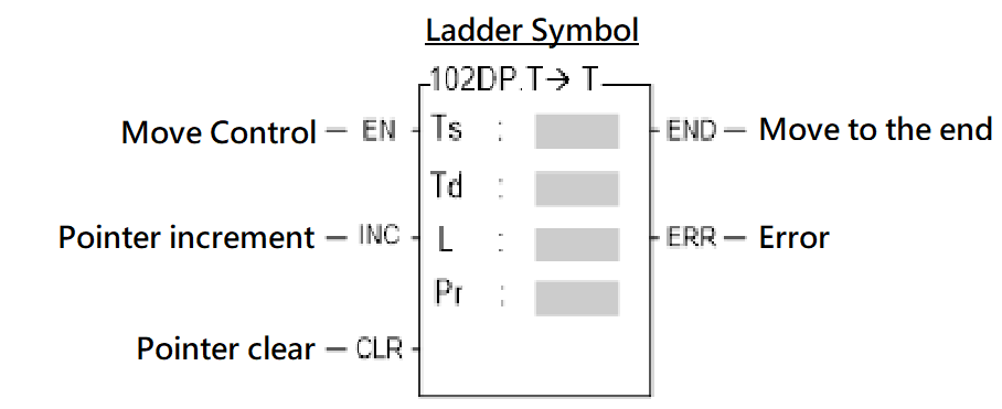
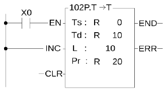
Ts: the starting number of the register in the source list Td: the starting number of the register of the destination list L: list length (Ts and Td) Pr: index register number Ts, Td can be combined with V, Z, P0~P9 for indirect addressing applications. |
|||||||||||||||||||||||||||||||||||||||||||||||||||||||||||||||||||||||||||||||||||||||||||||||||||||||||||||||||||||||||
|
||||||||||||||||||||||||||||||||||||||||||||||||||||||||||||||||||||||||||||||||||||||||||||||||||||||||||||||||||||||||||
|
Description |
||||||||||||||||||||||||||||||||||||||||||||||||||||||||||||||||||||||||||||||||||||||||||||||||||||||||||||||||||||||||||
|
||||||||||||||||||||||||||||||||||||||||||||||||||||||||||||||||||||||||||||||||||||||||||||||||||||||||||||||||||||||||||
|
FUN102 D P T→T |
(TABLE TO TABLE MOVE) |
FUN102 D P T→T |
||||||||||||||||||||||||||||||||||||||||||||||||||||||||||||||||||||||||||||||||||||||||||||||||||||||||||||||||||||||||
|
||||||||||||||||||||||||||||||||||||||||||||||||||||||||||||||||||||||||||||||||||||||||||||||||||||||||||||||||||||||||||
|
Example |
||||||||||||||||||||||||||||||||||||||||||||||||||||||||||||||||||||||||||||||||||||||||||||||||||||||||||||||||||||||||||
|
||||||||||||||||||||||||||||||||||||||||||||||||||||||||||||||||||||||||||||||||||||||||||||||||||||||||||||||||||||||||||

7-14-4 BLOCK TABLE MOVE (BT_M)
|
FUN103 D P BT_M |
BLOCK TABLE MOVE |
FUN103 D P BT_M |
||||||||||||||||||||||||||||||||||||||||||||||||||||||||||||||||||||||||||||||||
|
Symbol |
||||||||||||||||||||||||||||||||||||||||||||||||||||||||||||||||||||||||||||||||||
|
|
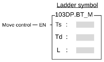
Ts : Starting register for source table Td : Starting register for destination table L : Lengths of source and destination tables Ts, Td may combine with V, Z, P0~P9 to serve indirect |
|||||||||||||||||||||||||||||||||||||||||||||||||||||||||||||||||||||||||||||||||
|
||||||||||||||||||||||||||||||||||||||||||||||||||||||||||||||||||||||||||||||||||
|
Description |
||||||||||||||||||||||||||||||||||||||||||||||||||||||||||||||||||||||||||||||||||
|
||||||||||||||||||||||||||||||||||||||||||||||||||||||||||||||||||||||||||||||||||
|
FUN103 D P BT_M |
BLOCK TABLE MOVE |
FUN103 D P BT_M |
||||
|
Example |
||||||
|
||||||
7-14-5 REGISTER TO TABLE SEARCH
|
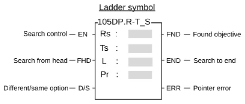
FUN105 D P R-T_S |
REGISTER TO TABLE SEARCH |
FUN105 D P R-T_S |
||||||||||||||||||||||||||||||||||||||||||||||||||||||||||||||||||||||||||||||||||||||||||||||||
|
Symbol |
||||||||||||||||||||||||||||||||||||||||||||||||||||||||||||||||||||||||||||||||||||||||||||||||||
|
|
Rs : Data to search, it can be a constant or a register Ts : Starting register of table being searched L : Label length Pr : Pointer of table Rs, Ts may combine with V, Z, P0~P9 to serve indirect address application |
|||||||||||||||||||||||||||||||||||||||||||||||||||||||||||||||||||||||||||||||||||||||||||||||||
|
||||||||||||||||||||||||||||||||||||||||||||||||||||||||||||||||||||||||||||||||||||||||||||||||||
|
Description |
||||||||||||||||||||||||||||||||||||||||||||||||||||||||||||||||||||||||||||||||||||||||||||||||||
|
||||||||||||||||||||||||||||||||||||||||||||||||||||||||||||||||||||||||||||||||||||||||||||||||||
|
FUN105 D P R-T_S |
REGISTER TO TABLE SEARCH |
FUN105 D P R-T_S |
|||||||||||||||||||||||||||||||||||||||||||||||||||||||||||||||||||||||||||||||||||||||||||||||||||||||||||||||||||||||||||||||||||||||||||
|
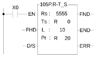
Example |
|||||||||||||||||||||||||||||||||||||||||||||||||||||||||||||||||||||||||||||||||||||||||||||||||||||||||||||||||||||||||||||||||||||||||||||
|
|||||||||||||||||||||||||||||||||||||||||||||||||||||||||||||||||||||||||||||||||||||||||||||||||||||||||||||||||||||||||||||||||||||||||||||
|
|||||||||||||||||||||||||||||||||||||||||||||||||||||||||||||||||||||||||||||||||||||||||||||||||||||||||||||||||||||||||||||||||||||||||||||

7-14-6 TABLE TO TABLE COMPARE
|
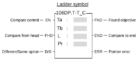
FUN106 D P T-T_C |
TABLE TO TABLE COMPARE |
FUN106 D P T-T_C |
||||||||||||||||||||||||||||||||||||||||||||||||||||||||||||||||||||||||||||||||||||||||||||||||
|
Symbol |
||||||||||||||||||||||||||||||||||||||||||||||||||||||||||||||||||||||||||||||||||||||||||||||||||
|
|
Ta : Starting register of Table a Tb : Starting register of Table b L : Lengths of Table Pr : Pointer Ta, Tb may combine with V, Z, P0~P9 to serve indirect address application |
|||||||||||||||||||||||||||||||||||||||||||||||||||||||||||||||||||||||||||||||||||||||||||||||||
|
||||||||||||||||||||||||||||||||||||||||||||||||||||||||||||||||||||||||||||||||||||||||||||||||||
|
Description |
||||||||||||||||||||||||||||||||||||||||||||||||||||||||||||||||||||||||||||||||||||||||||||||||||
|
||||||||||||||||||||||||||||||||||||||||||||||||||||||||||||||||||||||||||||||||||||||||||||||||||
|
FUN106 D P T-T_C |
TABLE TO TABLE COMPARE |
FUN106 D P T-T_C |
||||||||||||||||||||||||||||||||||||||||||||||||||||||||||||||||||||||||||||||||||||||||||||||||||||||||||||||||||||||||||||||||||||||||||||||||||||||||||||||||||||||||||||||||||||
|
Example |
||||||||||||||||||||||||||||||||||||||||||||||||||||||||||||||||||||||||||||||||||||||||||||||||||||||||||||||||||||||||||||||||||||||||||||||||||||||||||||||||||||||||||||||||||||||
|
||||||||||||||||||||||||||||||||||||||||||||||||||||||||||||||||||||||||||||||||||||||||||||||||||||||||||||||||||||||||||||||||||||||||||||||||||||||||||||||||||||||||||||||||||||||
|
||||||||||||||||||||||||||||||||||||||||||||||||||||||||||||||||||||||||||||||||||||||||||||||||||||||||||||||||||||||||||||||||||||||||||||||||||||||||||||||||||||||||||||||||||||||
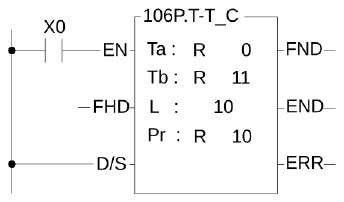

7-14-7 TABLE FILL (T_FIL)
|
FUN107 D P T_FIL |
TABLE FILL |
FUN107 D P T_FIL |
||||||||||||||||||||||||||||||||||||||||||||||||||||||||||||||||||||||||||||||||
|
Symbol |
||||||||||||||||||||||||||||||||||||||||||||||||||||||||||||||||||||||||||||||||||
|
|
Rs : Source data to fill, can be a constant or a register Td : Starting register of destination table L :Table length Rs, Td may combine with V, Z, P0~P9 to serve indirect address application |
|||||||||||||||||||||||||||||||||||||||||||||||||||||||||||||||||||||||||||||||||
|
||||||||||||||||||||||||||||||||||||||||||||||||||||||||||||||||||||||||||||||||||
|
Description |
||||||||||||||||||||||||||||||||||||||||||||||||||||||||||||||||||||||||||||||||||
|
||||||||||||||||||||||||||||||||||||||||||||||||||||||||||||||||||||||||||||||||||
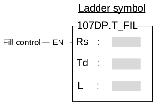
|
FUN107 D P T_FIL |
TABLE FILL |
FUN107 D P T_FIL |
||||||||||||||||||||||||||||||||||||||||||||||||||||||||||||||||||||||||||||||||||
|
Example |
||||||||||||||||||||||||||||||||||||||||||||||||||||||||||||||||||||||||||||||||||||
|
||||||||||||||||||||||||||||||||||||||||||||||||||||||||||||||||||||||||||||||||||||

7-14-8 TABLE SHIFT
|
FUN108 D P T_SHF |
TABLE SHIFT |
FUN108 D P T_SHF |
||||||||||||||||||||||||||||||||||||||||||||||||||||||||||||||||||||||||||||||||||||||||||||||||||||||||||||||||
|
Symbol |
||||||||||||||||||||||||||||||||||||||||||||||||||||||||||||||||||||||||||||||||||||||||||||||||||||||||||||||||||
|
|
IW: Data to fill the room after shift operation, can be a constant or a register Ts: Source table Td: Destination table storing shift results L: Lengths of tables Ts and Td OW: Register to accept the shifted-out data Ts, Td may combine with V, Z, P0~P9 to serve indirect address application |
|||||||||||||||||||||||||||||||||||||||||||||||||||||||||||||||||||||||||||||||||||||||||||||||||||||||||||||||||
|
||||||||||||||||||||||||||||||||||||||||||||||||||||||||||||||||||||||||||||||||||||||||||||||||||||||||||||||||||
|
Description |
||||||||||||||||||||||||||||||||||||||||||||||||||||||||||||||||||||||||||||||||||||||||||||||||||||||||||||||||||
|
||||||||||||||||||||||||||||||||||||||||||||||||||||||||||||||||||||||||||||||||||||||||||||||||||||||||||||||||||
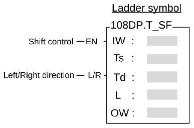
|
FUN108 D P T_SHF |
TABLE SHIFT |
FUN108 D P T_SHF |
|||||||||||||||||||||||||||||||||||||||||||||||||||||||||||||||||||||||||||||||||||||||||||||||||||||||||||||||||||||||||||||||||||||||||||||||||||||||||||||||||||||||||||||||||||||||||||||||||||||||||||||||
|
Example |
|||||||||||||||||||||||||||||||||||||||||||||||||||||||||||||||||||||||||||||||||||||||||||||||||||||||||||||||||||||||||||||||||||||||||||||||||||||||||||||||||||||||||||||||||||||||||||||||||||||||||||||||||
|
|||||||||||||||||||||||||||||||||||||||||||||||||||||||||||||||||||||||||||||||||||||||||||||||||||||||||||||||||||||||||||||||||||||||||||||||||||||||||||||||||||||||||||||||||||||||||||||||||||||||||||||||||
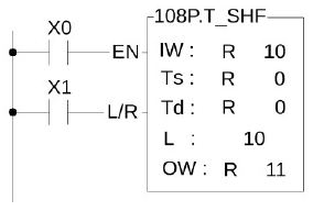
7-14-9 TABLE ROTATE
|
FUN109 D P T_ROT |
TABLE ROTATE |
FUN109 D P T_ROT |
||||||||||||||||||||||||||||||||||||||||||||||||||||||||||||||||||||||||||||||||
|
Symbol |
||||||||||||||||||||||||||||||||||||||||||||||||||||||||||||||||||||||||||||||||||
|
|
Ts : Source table for rotate Td : Destination table storing results of rotation L : Lengths of table Ts, Td may combine with V, Z, P0~P9 to serve indirect address application |
|||||||||||||||||||||||||||||||||||||||||||||||||||||||||||||||||||||||||||||||||
|
||||||||||||||||||||||||||||||||||||||||||||||||||||||||||||||||||||||||||||||||||
|
Description |
||||||||||||||||||||||||||||||||||||||||||||||||||||||||||||||||||||||||||||||||||
|
||||||||||||||||||||||||||||||||||||||||||||||||||||||||||||||||||||||||||||||||||

|
FUN109 D P T_ROT |
TABLE ROTATE |
FUN109 D P T_ROT |
||||||||||||||||||||||||||||||||||||||||||||||||||||||||||||||||||||||||||||||||||||||||||||||||||||||||||||||||||||||||||||||||||||||||
|
Example |
||||||||||||||||||||||||||||||||||||||||||||||||||||||||||||||||||||||||||||||||||||||||||||||||||||||||||||||||||||||||||||||||||||||||||
|
||||||||||||||||||||||||||||||||||||||||||||||||||||||||||||||||||||||||||||||||||||||||||||||||||||||||||||||||||||||||||||||||||||||||||
|
||||||||||||||||||||||||||||||||||||||||||||||||||||||||||||||||||||||||||||||||||||||||||||||||||||||||||||||||||||||||||||||||||||||||||
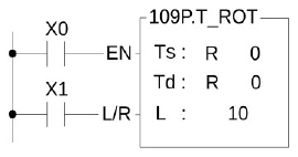
7-14-10 QUEUE
|
FUN110 D P QUEUE |
QUEUE |
FUN110 D P QUEUE |
||||||||||||||||||||||||||||||||||||||||||||||||||||||||||||||||||||||||||||||||||||||||||||||||||||||||||||||||
|
Symbol |
||||||||||||||||||||||||||||||||||||||||||||||||||||||||||||||||||||||||||||||||||||||||||||||||||||||||||||||||||
|
|
IW: the data to be inserted into the storage column or its register number QU: The starting register number of the storage row L: the length of the storage column PR: index register number OW: Register number receiving data moved out from the memory QU can be combined with V, Z, P0~P9 for indirect addressing application |
|||||||||||||||||||||||||||||||||||||||||||||||||||||||||||||||||||||||||||||||||||||||||||||||||||||||||||||||||
|
||||||||||||||||||||||||||||||||||||||||||||||||||||||||||||||||||||||||||||||||||||||||||||||||||||||||||||||||||
|
Description |
||||||||||||||||||||||||||||||||||||||||||||||||||||||||||||||||||||||||||||||||||||||||||||||||||||||||||||||||||
Note: The system uses the serial number L+1 register for internal calculations, users must avoid this register
|
||||||||||||||||||||||||||||||||||||||||||||||||||||||||||||||||||||||||||||||||||||||||||||||||||||||||||||||||||
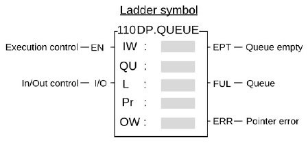
|
FUN110 D P QUEUE |
QUEUE |
FUN110 D P QUEUE |
|||||||||||||||||||||||||||||||||||||||||||||||||||||||||||||||||||||||||||||||||
|
|||||||||||||||||||||||||||||||||||||||||||||||||||||||||||||||||||||||||||||||||||

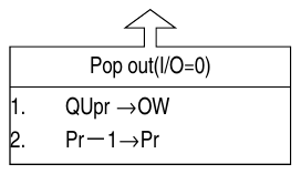
|
FUN110 D P QUEUE |
QUEUE |
FUN110 D P QUEUE |
||||||||||||||||||||||||||||||||||||||||||||||||||||||||||||||||||||||||||||||||||||||||||||||||||||||||||||||||||||||||||||||||||||||||||||||||||||||||||||||||||||||||||||||||
|
Example |
||||||||||||||||||||||||||||||||||||||||||||||||||||||||||||||||||||||||||||||||||||||||||||||||||||||||||||||||||||||||||||||||||||||||||||||||||||||||||||||||||||||||||||||||||
|
||||||||||||||||||||||||||||||||||||||||||||||||||||||||||||||||||||||||||||||||||||||||||||||||||||||||||||||||||||||||||||||||||||||||||||||||||||||||||||||||||||||||||||||||||

7-14-11 STACK
|
FUN111 D P STACK |
STACK |
FUN111 D P STACK |
||||||||||||||||||||||||||||||||||||||||||||||||||||||||||||||||||||||||||||||||||||||||||||||||||||||||||||||||
|
Symbol |
||||||||||||||||||||||||||||||||||||||||||||||||||||||||||||||||||||||||||||||||||||||||||||||||||||||||||||||||||
|
|
IW : Data pushed into stack, can be a constant or a register ST : Starting register of stack L : Size of stack Pr : Pointer register OW : Register accepting data popped out from stack ST may combine with V, Z, P0~P9 to serve indirect address application |
|||||||||||||||||||||||||||||||||||||||||||||||||||||||||||||||||||||||||||||||||||||||||||||||||||||||||||||||||
|
||||||||||||||||||||||||||||||||||||||||||||||||||||||||||||||||||||||||||||||||||||||||||||||||||||||||||||||||||
|
Description |
||||||||||||||||||||||||||||||||||||||||||||||||||||||||||||||||||||||||||||||||||||||||||||||||||||||||||||||||||
|
||||||||||||||||||||||||||||||||||||||||||||||||||||||||||||||||||||||||||||||||||||||||||||||||||||||||||||||||||
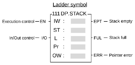
|
FUN111 D P STACK |
STACK |
FUN111 D P STACK |
||||||||||||||||||||||||||||||||||||||||||||||||||||||||||||||||||||||||||||||||||||
|
||||||||||||||||||||||||||||||||||||||||||||||||||||||||||||||||||||||||||||||||||||||


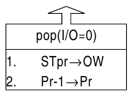
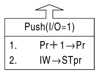
|
FUN111 D P STACK |
STACK |
FUN111 D P STACK |
||||||||||||||||||||||||||||||||||||||||||||||||||||||||||||||||||||||||||||||||||||||||||||||||||||||||||||||||||||||||||||||||||||||||||||||||||||||||||||||||||||||||||||||||
|
Example |
||||||||||||||||||||||||||||||||||||||||||||||||||||||||||||||||||||||||||||||||||||||||||||||||||||||||||||||||||||||||||||||||||||||||||||||||||||||||||||||||||||||||||||||||||
|
||||||||||||||||||||||||||||||||||||||||||||||||||||||||||||||||||||||||||||||||||||||||||||||||||||||||||||||||||||||||||||||||||||||||||||||||||||||||||||||||||||||||||||||||||
7-14-12 BLOCK COMPARE (DRUM)
|
FUN112 D P BKCMP |
BLOCK COMPARE (DRUM) |
FUN112 D P BKCMP |
||||||||||||||||||||||||||||||||||||||||||||||||||||||||||||||||||||||||||||||||||||||||||||||||||||||
|
Symbol |
||||||||||||||||||||||||||||||||||||||||||||||||||||||||||||||||||||||||||||||||||||||||||||||||||||||||
|
|
Rs : Data for compare, can be a constant or a register Ts : Starting register block storing upper and lower limit L : Number of pairs of upper and lower limits D : Starting relay storing results of comparison |
|||||||||||||||||||||||||||||||||||||||||||||||||||||||||||||||||||||||||||||||||||||||||||||||||||||||
|
||||||||||||||||||||||||||||||||||||||||||||||||||||||||||||||||||||||||||||||||||||||||||||||||||||||||
|
Description |
||||||||||||||||||||||||||||||||||||||||||||||||||||||||||||||||||||||||||||||||||||||||||||||||||||||||
|
||||||||||||||||||||||||||||||||||||||||||||||||||||||||||||||||||||||||||||||||||||||||||||||||||||||||
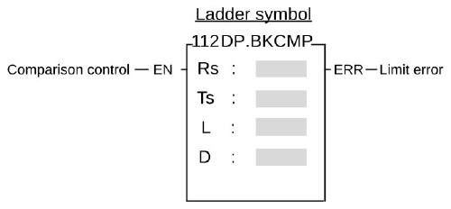
|
FUN112 D P BKCMP |
BLOCK COMPARE(DRUM) |
FUN112 D P BKCMP |
|||||||||||||||||||||||||||||||||||
|
Example |
|||||||||||||||||||||||||||||||||||||
|
|||||||||||||||||||||||||||||||||||||
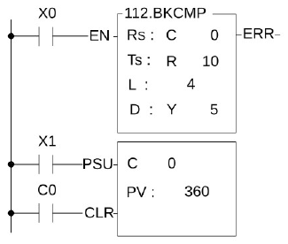
|
FUN112 D P BKCMP |
BLOCK COMPARE(DRUM) |
FUN112 D P BKCMP |
Equivalent mechanical drum emulated by above program
|
||
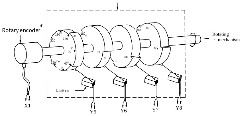
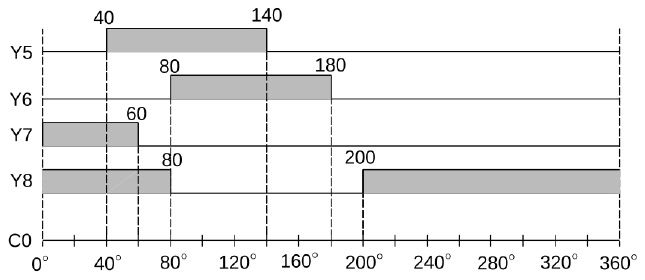
7-14-13 DATA SORTING (SORTING)
|
FUN113 D P SORT |
SORTING |
FUN113 D P SORT |
|||||||||||||||||||||||||||||||||||||||||||||||||||||||||||||||||||||||||||
|
Symbol |
|||||||||||||||||||||||||||||||||||||||||||||||||||||||||||||||||||||||||||||
|
|
S : Starting register of source registers to sort D : Starting register of destination registers to store the data after sorted L : Total register for sorting |
||||||||||||||||||||||||||||||||||||||||||||||||||||||||||||||||||||||||||||
|
|||||||||||||||||||||||||||||||||||||||||||||||||||||||||||||||||||||||||||||
|
Description |
|||||||||||||||||||||||||||||||||||||||||||||||||||||||||||||||||||||||||||||
|
|||||||||||||||||||||||||||||||||||||||||||||||||||||||||||||||||||||||||||||

|
FUN113 D P SORT |
DATA SORTING |
FUN113 D P SORT |
||||||||||||||||||||||||||||||||||||||||||||||||||
|
Example |
||||||||||||||||||||||||||||||||||||||||||||||||||||
|
||||||||||||||||||||||||||||||||||||||||||||||||||||

 2796
 9788
7-14-14 ZONE WRITE
|
FUN114 D P Z-WR |
ZONE WRITE |
FUN114 D P Z-WR |
||||||||||||||||||||||||||||||||||||||||||||||||||||||||||||||||||||
|
Symbol |
||||||||||||||||||||||||||||||||||||||||||||||||||||||||||||||||||||||
|
|
D : Starting address of being set or reset N : Quantity of being set oe reset, 1~511 D、N operand can combine V、Z、P0~P9 for index addressing while word operation |
|||||||||||||||||||||||||||||||||||||||||||||||||||||||||||||||||||||
|
||||||||||||||||||||||||||||||||||||||||||||||||||||||||||||||||||||||
|
Description |
||||||||||||||||||||||||||||||||||||||||||||||||||||||||||||||||||||||
|
||||||||||||||||||||||||||||||||||||||||||||||||||||||||||||||||||||||
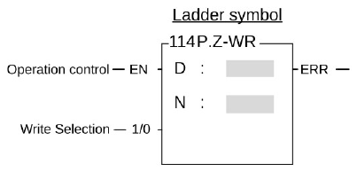
|
FUN114 D P Z-WR |
ZONE WRITE |
FUN114 D P Z-WR |
||||
|
Example 1 |
Registers R0~R9 will be reset to 0 while X0=1 |
|||||
|
||||||

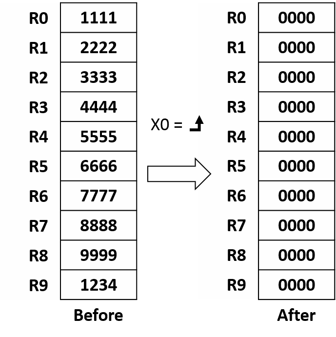
|
FUN114 D P Z-WR |
ZONE WRITE |
FUN114 D P Z-WR |
||||
|
Example 2 |
(When X50 is “ON”, clear M5~M11 to 0) |
|||||
|
||||||
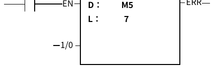
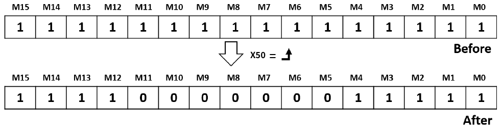
Matrix Instructions
120. MAND 126. MBRD
121. MOR 127. MBWR
122. MXOR 128. MBSHF
123. MXNR 129. MBROT
124. MINV 130. MBCNT
125. MCMP
- A matrix is comprised of 2 or more consecutive 16-bit registers. The number of registers comprising the matrix is called the matrix length (L). One matrix altogether has L×16 bits (points), and the basic unit of the object for each operation is bit.
- The matrix instructions treats the 16×L matrix bits as a set of series points(denoted by M0 to M16L-1). Whether the matrix is formed by register or not, the operation object is the bit not numerical value.
- Matrix instructions are used mostly for discrete status processing such as moving, copying, comparing, searching, etc, of single point to multipoint (matrix), or multipoint-to-multipoint. These instructions are convenient, important for application.
- Among the matrix instructions, most instruction need to use a 16-bit register as a pointer to points a specific point within the matrix. This register is known as the matrix pointer (Pr). Its effective range is 0 to 16L-1, which corresponds respectively to the bits M0 to M16L-1 within the matrix.
- Among the matrix operations, there are shift left/right, rotate left/right operations. We define the movement toward higher bit is left direction, while the movement toward lower bit is right direction, as shown in the diagram below.

7-15 Matrix Instruction (FUN120~130)
7-15-1 MATRIX AND
|
FUN120 P MAND |
MATRIX AND |
FUN120 P MAND |
||||||||||||||||||||||||||||||||||||||||||||||||||||||||||||||||||||||||||||||||||||||||||
|
Symbol |
||||||||||||||||||||||||||||||||||||||||||||||||||||||||||||||||||||||||||||||||||||||||||||
|
|
Ma : Starting register of source matrix a Mb : Starting register of source matrix b Md : Starting register of destination matrix L : Length of matrix (Ma, Mb and Md) Ma, Mb, Md may combine with V, Z, P0~P9 to serve indirect address application |
|||||||||||||||||||||||||||||||||||||||||||||||||||||||||||||||||||||||||||||||||||||||||||
|
||||||||||||||||||||||||||||||||||||||||||||||||||||||||||||||||||||||||||||||||||||||||||||
|
Description |
||||||||||||||||||||||||||||||||||||||||||||||||||||||||||||||||||||||||||||||||||||||||||||
|
||||||||||||||||||||||||||||||||||||||||||||||||||||||||||||||||||||||||||||||||||||||||||||
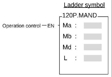
|
FUN120 P MAND |
MATRIX AND |
FUN120 P MAND |
||||||||||||||||||||||||||||||||||||||||||||||||||||||||||||||||||||||||||||||||||||||||||||||||||||||||||||||||||||||||||||||||||||||||||||||||||||||||||||||||||||||||||||||||||||||||||||||||||||||||||||||||||||||||||||||||||||||||||||||||||||||||||||||||||||||||||||||||||||||||||||||||||||||||||||||||||||||||||||||||||||||||||||||||||||||||||||||||||||||||||||||||||||||||||||||||||||||||||||||||||||||||||||||||||||||||||||||||||||||||||||||||||||||||||||||||||||||||||||||||||||||||||||||||
|
|
||||||||||||||||||||||||||||||||||||||||||||||||||||||||||||||||||||||||||||||||||||||||||||||||||||||||||||||||||||||||||||||||||||||||||||||||||||||||||||||||||||||||||||||||||||||||||||||||||||||||||||||||||||||||||||||||||||||||||||||||||||||||||||||||||||||||||||||||||||||||||||||||||||||||||||||||||||||||||||||||||||||||||||||||||||||||||||||||||||||||||||||||||||||||||||||||||||||||||||||||||||||||||||||||||||||||||||||||||||||||||||||||||||||||||||||||||||||||||||||||||||||||||||||||||
|
Example |
||||||||||||||||||||||||||||||||||||||||||||||||||||||||||||||||||||||||||||||||||||||||||||||||||||||||||||||||||||||||||||||||||||||||||||||||||||||||||||||||||||||||||||||||||||||||||||||||||||||||||||||||||||||||||||||||||||||||||||||||||||||||||||||||||||||||||||||||||||||||||||||||||||||||||||||||||||||||||||||||||||||||||||||||||||||||||||||||||||||||||||||||||||||||||||||||||||||||||||||||||||||||||||||||||||||||||||||||||||||||||||||||||||||||||||||||||||||||||||||||||||||||||||||||||
|
||||||||||||||||||||||||||||||||||||||||||||||||||||||||||||||||||||||||||||||||||||||||||||||||||||||||||||||||||||||||||||||||||||||||||||||||||||||||||||||||||||||||||||||||||||||||||||||||||||||||||||||||||||||||||||||||||||||||||||||||||||||||||||||||||||||||||||||||||||||||||||||||||||||||||||||||||||||||||||||||||||||||||||||||||||||||||||||||||||||||||||||||||||||||||||||||||||||||||||||||||||||||||||||||||||||||||||||||||||||||||||||||||||||||||||||||||||||||||||||||||||||||||||||||||
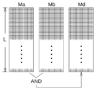
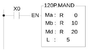
7-15-2 MATRIX OR
|
FUN121 P MOR |
MATRIX OR |
FUN121 P MOR |
|||||||||||||||||||||||||||||||||||||||||||||||||||||||||||||||||||||||||||||||||||||||||||||||||||||||||||||||||||||||||||||||||||||||||||||||||||||||||||||||||||||||||||||||||||||||||||||||||||||||||||||||||||||||||||||||||||||||||||||||||||||||||||||||||||||||||||||||||||||||||||||||||||||||||||||||||||||||||||||||||||||||||||||||||||||||||||||||||||||||||||||||||||||||||||||||||||||||||||||||||||||||||||||||||||||||||||||||||||||||||||||||||||||||||||||
|
Symbol |
|||||||||||||||||||||||||||||||||||||||||||||||||||||||||||||||||||||||||||||||||||||||||||||||||||||||||||||||||||||||||||||||||||||||||||||||||||||||||||||||||||||||||||||||||||||||||||||||||||||||||||||||||||||||||||||||||||||||||||||||||||||||||||||||||||||||||||||||||||||||||||||||||||||||||||||||||||||||||||||||||||||||||||||||||||||||||||||||||||||||||||||||||||||||||||||||||||||||||||||||||||||||||||||||||||||||||||||||||||||||||||||||||||||||||||||||
|
|
Ma : Starting register of source matrix a Mb : Starting register of source matrix b Md : Starting register of destination matrix L : Length of matrix (Ma, Mb and Md) Ma, Mb, Md may combine with V, Z, P0~P9 to serve indirect address application |
||||||||||||||||||||||||||||||||||||||||||||||||||||||||||||||||||||||||||||||||||||||||||||||||||||||||||||||||||||||||||||||||||||||||||||||||||||||||||||||||||||||||||||||||||||||||||||||||||||||||||||||||||||||||||||||||||||||||||||||||||||||||||||||||||||||||||||||||||||||||||||||||||||||||||||||||||||||||||||||||||||||||||||||||||||||||||||||||||||||||||||||||||||||||||||||||||||||||||||||||||||||||||||||||||||||||||||||||||||||||||||||||||||||||||||||
|
|||||||||||||||||||||||||||||||||||||||||||||||||||||||||||||||||||||||||||||||||||||||||||||||||||||||||||||||||||||||||||||||||||||||||||||||||||||||||||||||||||||||||||||||||||||||||||||||||||||||||||||||||||||||||||||||||||||||||||||||||||||||||||||||||||||||||||||||||||||||||||||||||||||||||||||||||||||||||||||||||||||||||||||||||||||||||||||||||||||||||||||||||||||||||||||||||||||||||||||||||||||||||||||||||||||||||||||||||||||||||||||||||||||||||||||||
|
Description |
|||||||||||||||||||||||||||||||||||||||||||||||||||||||||||||||||||||||||||||||||||||||||||||||||||||||||||||||||||||||||||||||||||||||||||||||||||||||||||||||||||||||||||||||||||||||||||||||||||||||||||||||||||||||||||||||||||||||||||||||||||||||||||||||||||||||||||||||||||||||||||||||||||||||||||||||||||||||||||||||||||||||||||||||||||||||||||||||||||||||||||||||||||||||||||||||||||||||||||||||||||||||||||||||||||||||||||||||||||||||||||||||||||||||||||||||
|
|||||||||||||||||||||||||||||||||||||||||||||||||||||||||||||||||||||||||||||||||||||||||||||||||||||||||||||||||||||||||||||||||||||||||||||||||||||||||||||||||||||||||||||||||||||||||||||||||||||||||||||||||||||||||||||||||||||||||||||||||||||||||||||||||||||||||||||||||||||||||||||||||||||||||||||||||||||||||||||||||||||||||||||||||||||||||||||||||||||||||||||||||||||||||||||||||||||||||||||||||||||||||||||||||||||||||||||||||||||||||||||||||||||||||||||||
|
FUN121 P MOR |
MATRIX OR |
FUN121 P MOR |
|||||||||||||||||||||||||||||||||||||||||||||||||||||||||||||||||||||||||||||||||||||||||||||||||||||||||||||||||||||||||||||||||||||||||||||||||||||||||||||||||||||||||||||||||||||||||||||||||||||||||||||||||||||||||||||||||||||||||||||||||||||||||||||||||||||||||||||||||||||||||||||||||||||||||||||||||||||||||||||||||||||||||||||||||||||||||||||||||||||||||||||||||||||||||||||||||||||||||||||||||||||||||||||||||||||||||||||||||||||||||||||||||||||||||||||
|
|
|||||||||||||||||||||||||||||||||||||||||||||||||||||||||||||||||||||||||||||||||||||||||||||||||||||||||||||||||||||||||||||||||||||||||||||||||||||||||||||||||||||||||||||||||||||||||||||||||||||||||||||||||||||||||||||||||||||||||||||||||||||||||||||||||||||||||||||||||||||||||||||||||||||||||||||||||||||||||||||||||||||||||||||||||||||||||||||||||||||||||||||||||||||||||||||||||||||||||||||||||||||||||||||||||||||||||||||||||||||||||||||||||||||||||||||||
|
Example |
|||||||||||||||||||||||||||||||||||||||||||||||||||||||||||||||||||||||||||||||||||||||||||||||||||||||||||||||||||||||||||||||||||||||||||||||||||||||||||||||||||||||||||||||||||||||||||||||||||||||||||||||||||||||||||||||||||||||||||||||||||||||||||||||||||||||||||||||||||||||||||||||||||||||||||||||||||||||||||||||||||||||||||||||||||||||||||||||||||||||||||||||||||||||||||||||||||||||||||||||||||||||||||||||||||||||||||||||||||||||||||||||||||||||||||||||
|
|||||||||||||||||||||||||||||||||||||||||||||||||||||||||||||||||||||||||||||||||||||||||||||||||||||||||||||||||||||||||||||||||||||||||||||||||||||||||||||||||||||||||||||||||||||||||||||||||||||||||||||||||||||||||||||||||||||||||||||||||||||||||||||||||||||||||||||||||||||||||||||||||||||||||||||||||||||||||||||||||||||||||||||||||||||||||||||||||||||||||||||||||||||||||||||||||||||||||||||||||||||||||||||||||||||||||||||||||||||||||||||||||||||||||||||||
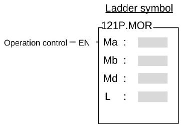
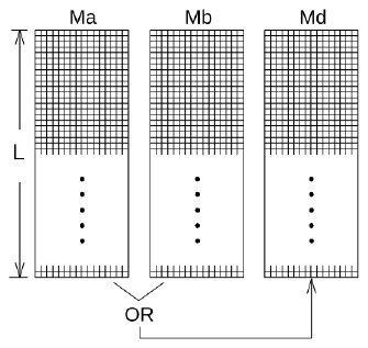

7-15-3 MATRIX EXCLUSIVE OR
|
FUN122 P MXOR |
MATRIX EXCLUSIVE OR |
FUN122 P MXOR |
||||||||||||||||||||||||||||||||||||||||||||||||||||||||||||||||||||||||||||||||||||||||||
|
Symbol |
||||||||||||||||||||||||||||||||||||||||||||||||||||||||||||||||||||||||||||||||||||||||||||
|
|
Ma : Starting register of source matrix a Mb : Starting register of source matrix b Md : Starting register of destination matrix L : Length of matrix (Ma, Mb and Md) Ma, Mb, Md may combine with V, Z, P0~P9 to serve indirect address application |
|||||||||||||||||||||||||||||||||||||||||||||||||||||||||||||||||||||||||||||||||||||||||||
|
||||||||||||||||||||||||||||||||||||||||||||||||||||||||||||||||||||||||||||||||||||||||||||
|
Description |
||||||||||||||||||||||||||||||||||||||||||||||||||||||||||||||||||||||||||||||||||||||||||||
|
||||||||||||||||||||||||||||||||||||||||||||||||||||||||||||||||||||||||||||||||||||||||||||

|
FUN122 P MXOR |
MATRIX EXCLUSIVE OR |
FUN122 P MXOR |
||||||||||||||||||||||||||||||||||||||||||||||||||||||||||||||||||||||||||||||||||||||||||||||||||||||||||||||||||||||||||||||||||||||||||||||||||||||||||||||||||||||||||||||||||||||||||||||||||||||||||||||||||||||||||||||||||||||||||||||||||||||||||||||||||||||||||||||||||||||||||||||||||||||||||||||||||||||||||||||||||||||||||||||||||||||||||||||||||||||||||||||||||||||||||||||||||||||||||||||||||||||||||||||||||||||||||||||||||||||||||||||||||||||||||||
|
|
||||||||||||||||||||||||||||||||||||||||||||||||||||||||||||||||||||||||||||||||||||||||||||||||||||||||||||||||||||||||||||||||||||||||||||||||||||||||||||||||||||||||||||||||||||||||||||||||||||||||||||||||||||||||||||||||||||||||||||||||||||||||||||||||||||||||||||||||||||||||||||||||||||||||||||||||||||||||||||||||||||||||||||||||||||||||||||||||||||||||||||||||||||||||||||||||||||||||||||||||||||||||||||||||||||||||||||||||||||||||||||||||||||||||||||||
|
Example |
||||||||||||||||||||||||||||||||||||||||||||||||||||||||||||||||||||||||||||||||||||||||||||||||||||||||||||||||||||||||||||||||||||||||||||||||||||||||||||||||||||||||||||||||||||||||||||||||||||||||||||||||||||||||||||||||||||||||||||||||||||||||||||||||||||||||||||||||||||||||||||||||||||||||||||||||||||||||||||||||||||||||||||||||||||||||||||||||||||||||||||||||||||||||||||||||||||||||||||||||||||||||||||||||||||||||||||||||||||||||||||||||||||||||||||||
|
||||||||||||||||||||||||||||||||||||||||||||||||||||||||||||||||||||||||||||||||||||||||||||||||||||||||||||||||||||||||||||||||||||||||||||||||||||||||||||||||||||||||||||||||||||||||||||||||||||||||||||||||||||||||||||||||||||||||||||||||||||||||||||||||||||||||||||||||||||||||||||||||||||||||||||||||||||||||||||||||||||||||||||||||||||||||||||||||||||||||||||||||||||||||||||||||||||||||||||||||||||||||||||||||||||||||||||||||||||||||||||||||||||||||||||||
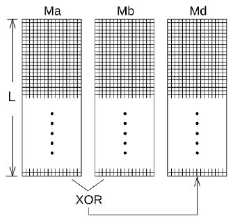
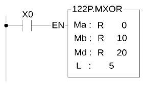
7-15-4 MATRIX ENCLUSIVE NOR
|
FUN123 P MXNR |
MATRIX EXCLUSIVE NOR |
FUN123 P MXNR |
||||||||||||||||||||||||||||||||||||||||||||||||||||||||||||||||||||||||||||||||||||||||||
|
Symbol |
||||||||||||||||||||||||||||||||||||||||||||||||||||||||||||||||||||||||||||||||||||||||||||
|
|
Ma : Starting register of source matrix a Mb : Starting register of source matrix b Md : Starting register of destination matrix L : Length of matrix (Ma, Mb and Md) Ma, Mb, Md may combine with V, Z,P0~P9 to serve indirect address application |
|||||||||||||||||||||||||||||||||||||||||||||||||||||||||||||||||||||||||||||||||||||||||||
|
||||||||||||||||||||||||||||||||||||||||||||||||||||||||||||||||||||||||||||||||||||||||||||
|
Description |
||||||||||||||||||||||||||||||||||||||||||||||||||||||||||||||||||||||||||||||||||||||||||||
|
||||||||||||||||||||||||||||||||||||||||||||||||||||||||||||||||||||||||||||||||||||||||||||

|
FUN123 P MXNR |
MATRIX EXCLUSIVE NOR |
FUN123 P MXNR |
||||||||||||||||||||||||||||||||||||||||||||||||||||||||||||||||||||||||||||||||||||||||||||||||||||||||||||||||||||||||||||||||||||||||||||||||||||||||||||||||||||||||||||||||||||||||||||||||||||||||||||||||||||||||||||||||||||||||||||||||||||||||||||||||||||||||||||||||||||||||||||||||||||||||||||||||||||||||||||||||||||||||||||||||||||||||||||||||||||||||||||||||||||||||||||||||||||||||||||||||||||||||||||||||||||||||||||||||||||||||||||||||||||
|
|
||||||||||||||||||||||||||||||||||||||||||||||||||||||||||||||||||||||||||||||||||||||||||||||||||||||||||||||||||||||||||||||||||||||||||||||||||||||||||||||||||||||||||||||||||||||||||||||||||||||||||||||||||||||||||||||||||||||||||||||||||||||||||||||||||||||||||||||||||||||||||||||||||||||||||||||||||||||||||||||||||||||||||||||||||||||||||||||||||||||||||||||||||||||||||||||||||||||||||||||||||||||||||||||||||||||||||||||||||||||||||||||||||||||
|
Example |
||||||||||||||||||||||||||||||||||||||||||||||||||||||||||||||||||||||||||||||||||||||||||||||||||||||||||||||||||||||||||||||||||||||||||||||||||||||||||||||||||||||||||||||||||||||||||||||||||||||||||||||||||||||||||||||||||||||||||||||||||||||||||||||||||||||||||||||||||||||||||||||||||||||||||||||||||||||||||||||||||||||||||||||||||||||||||||||||||||||||||||||||||||||||||||||||||||||||||||||||||||||||||||||||||||||||||||||||||||||||||||||||||||||
|
||||||||||||||||||||||||||||||||||||||||||||||||||||||||||||||||||||||||||||||||||||||||||||||||||||||||||||||||||||||||||||||||||||||||||||||||||||||||||||||||||||||||||||||||||||||||||||||||||||||||||||||||||||||||||||||||||||||||||||||||||||||||||||||||||||||||||||||||||||||||||||||||||||||||||||||||||||||||||||||||||||||||||||||||||||||||||||||||||||||||||||||||||||||||||||||||||||||||||||||||||||||||||||||||||||||||||||||||||||||||||||||||||||||
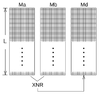
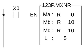
7-15-5 MATRIX INVERSE
|
FUN124 P MINV |
MATRIX INVERSE |
FUN124 P MINV |
|||||||||||||||||||||||||||||||||||||||||||||||||||||||||||||||||||||||||||
|
Symbol |
|||||||||||||||||||||||||||||||||||||||||||||||||||||||||||||||||||||||||||||
|
|
Ms: Starting register of source matrix Md : Starting register of destination L : Length of matrix (Ms and Md) Ma, Md may combine with V, Z, P0~P9 to serve indirect address application |
||||||||||||||||||||||||||||||||||||||||||||||||||||||||||||||||||||||||||||
|
|||||||||||||||||||||||||||||||||||||||||||||||||||||||||||||||||||||||||||||
|
Description |
|||||||||||||||||||||||||||||||||||||||||||||||||||||||||||||||||||||||||||||
|
|||||||||||||||||||||||||||||||||||||||||||||||||||||||||||||||||||||||||||||
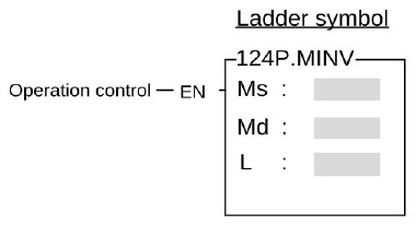
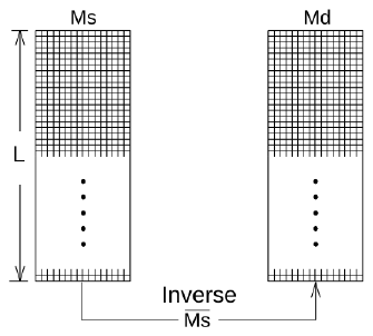
|
FUN124 P MINV |
MATRIX INVERSE |
FUN124 P MINV |
||||||||||||||||||||||||||||||||||||||||||||||||||||||||||||||||||||||||||||||||||||||||||||||||||||||||||||||||||||||||||||||||||||||||||||||||||||||||||||||||||||||||||||||||||||||||||||||||||||||||||||||||||||||||||||||||||||||||||||||||||||||||||||||||||||||||||||||||||
|
Exaxmple |
||||||||||||||||||||||||||||||||||||||||||||||||||||||||||||||||||||||||||||||||||||||||||||||||||||||||||||||||||||||||||||||||||||||||||||||||||||||||||||||||||||||||||||||||||||||||||||||||||||||||||||||||||||||||||||||||||||||||||||||||||||||||||||||||||||||||||||||||||||
|
||||||||||||||||||||||||||||||||||||||||||||||||||||||||||||||||||||||||||||||||||||||||||||||||||||||||||||||||||||||||||||||||||||||||||||||||||||||||||||||||||||||||||||||||||||||||||||||||||||||||||||||||||||||||||||||||||||||||||||||||||||||||||||||||||||||||||||||||||||
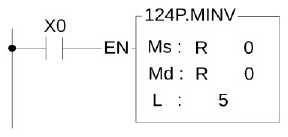
7-15-6 MATRIX BIT SHIFT
|
FUN128 P MBSHF |
MATRIX BIT SHIFT |
FUN128 P MBSHF |
|||||||||||||||||||||||||||||||||||||||||||||||||||||||||||||||||||||||||||
|
Symbol |
|||||||||||||||||||||||||||||||||||||||||||||||||||||||||||||||||||||||||||||
|
|
Ms : Starting register of source matrix Md : Starting register of destination matrix L : Length of matrix (Ms and Md) Ms, Md may combine with V, Z, P0~P9 to serve indirect address application |
||||||||||||||||||||||||||||||||||||||||||||||||||||||||||||||||||||||||||||
|
|||||||||||||||||||||||||||||||||||||||||||||||||||||||||||||||||||||||||||||
|
Description |
|||||||||||||||||||||||||||||||||||||||||||||||||||||||||||||||||||||||||||||
|
|||||||||||||||||||||||||||||||||||||||||||||||||||||||||||||||||||||||||||||
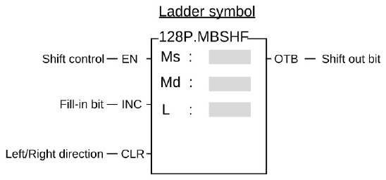
|
FUN128 P MBSHF |
(MATRIX BIT SHIFT) |
FUN128 P MBSHF |
||
|
||||

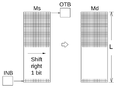
|
FUN128 P MBSHF |
(MATRIX BIT SHIFT) |
FUN128 P MBSHF |
||||||||||||||||||||||||||||||||||||||||||||||||||||||||||||||||||||||||||||||||||||||||||||||||||||||||||||||||||||||||||||||||||||||||||||||||||||||||||||||||||||||||||||||||||||||||||||||||||||||||||||||||||||||||||||||||||||||||||||||||||||||||||||||||||||||||||||||||||
|
Example |
||||||||||||||||||||||||||||||||||||||||||||||||||||||||||||||||||||||||||||||||||||||||||||||||||||||||||||||||||||||||||||||||||||||||||||||||||||||||||||||||||||||||||||||||||||||||||||||||||||||||||||||||||||||||||||||||||||||||||||||||||||||||||||||||||||||||||||||||||||
|
||||||||||||||||||||||||||||||||||||||||||||||||||||||||||||||||||||||||||||||||||||||||||||||||||||||||||||||||||||||||||||||||||||||||||||||||||||||||||||||||||||||||||||||||||||||||||||||||||||||||||||||||||||||||||||||||||||||||||||||||||||||||||||||||||||||||||||||||||||
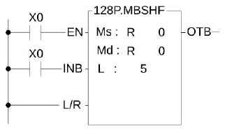
7-15-7 MATRIX BIT ROTATE
|
FUN129 P MBROT |
MATRIX BIT ROTATE |
FUN129 P MBROT |
|||||||||||||||||||||||||||||||||||||||||||||||||||||||||||||||||||||||||||
|
Symbol |
|||||||||||||||||||||||||||||||||||||||||||||||||||||||||||||||||||||||||||||
|
|
Ms : Starting register of source matrix Md : Starting register of destination matrix L : Length of matrix (Ms and Md) Ms, Md may combine with V, Z, P0~P9 to serve indirect address application |
||||||||||||||||||||||||||||||||||||||||||||||||||||||||||||||||||||||||||||
|
|||||||||||||||||||||||||||||||||||||||||||||||||||||||||||||||||||||||||||||
|
Description |
|||||||||||||||||||||||||||||||||||||||||||||||||||||||||||||||||||||||||||||
|
|||||||||||||||||||||||||||||||||||||||||||||||||||||||||||||||||||||||||||||
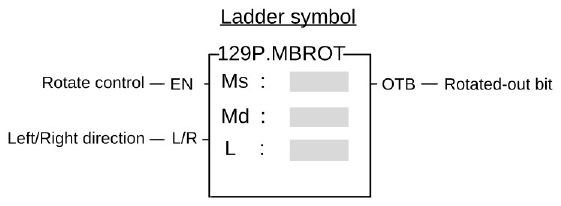
|
FUN129 P MBROT |
MATRIX BIT ROTATE |
FUN129 P MBROT |
|
|
||
|
|
||
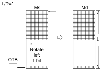
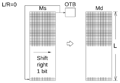
|
FUN129 P MBROT |
MATRIX BIT ROTATE |
FUN129 P MBROT |
||||||||||||||||||||||||||||||||||||||||||||||||||||||||||||||||||||||||||||||||||||||||||||||||||||||||||||||||||||||||||||||||||||||||||||||||||||||||||||||||||||||||||||||||||||||||||||||||||||||||||||||||||||||||||||||||||||||||||||||||||||||||||||||||||||||||||||||||||
|
Example |
||||||||||||||||||||||||||||||||||||||||||||||||||||||||||||||||||||||||||||||||||||||||||||||||||||||||||||||||||||||||||||||||||||||||||||||||||||||||||||||||||||||||||||||||||||||||||||||||||||||||||||||||||||||||||||||||||||||||||||||||||||||||||||||||||||||||||||||||||||
|
||||||||||||||||||||||||||||||||||||||||||||||||||||||||||||||||||||||||||||||||||||||||||||||||||||||||||||||||||||||||||||||||||||||||||||||||||||||||||||||||||||||||||||||||||||||||||||||||||||||||||||||||||||||||||||||||||||||||||||||||||||||||||||||||||||||||||||||||||||
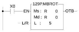

7-15-8 MATRIX BIT STATUS COUNT(MBCNT)
|
FUN130 P MBCNT |
MATRIX BIT STATUS COUNT |
FUN130 P MBCNT |
|||||||||||||||||||||||||||||||||||||||||||||||||||||||||||||||||||||||||||
|
Symbol |
|||||||||||||||||||||||||||||||||||||||||||||||||||||||||||||||||||||||||||||
|
|
Ms : Starting register of matrix L : Matrix length D : Register storing count results Ms may combine with V, Z, P0~P9 to serve indirect address application |
||||||||||||||||||||||||||||||||||||||||||||||||||||||||||||||||||||||||||||
|
|||||||||||||||||||||||||||||||||||||||||||||||||||||||||||||||||||||||||||||
|
Description |
|||||||||||||||||||||||||||||||||||||||||||||||||||||||||||||||||||||||||||||
|
|||||||||||||||||||||||||||||||||||||||||||||||||||||||||||||||||||||||||||||

|
FUN130 P MBCNT |
MATRIX BIT STATUS COUNT |
FUN130 P MBCNT |
||||
|
Example |
||||||
|
||||||


7-16 NC Positioning Instruction (FUN137~143)
7-16-1 ICA
|
FUN137 ICA |
ICA |
FUN137 ICA |
|||||||||||||||||||||||||||||||||||||||||||||||||||||||||||||||||||||||||||
|
Symbol |
|||||||||||||||||||||||||||||||||||||||||||||||||||||||||||||||||||||||||||||
|
|
Ps:The set number of Pulse Output (0~7) 0:Y0 & Y1 1:Y2 & Y3 2:Y4 & Y5 3:Y6 & Y7 4:MQ Y16 & Y17, Y8 & Y9 otherwise 5:MQ Y18 & Y19, Y10 & Y11 otherwise 6:MQ Y20 & Y21, Y12 & Y13 otherwise 7:MQ Y22 & Y23, Y14 & Y15 otherwise Is:MQ: X0~X23 or Y0~Y23 MA: X0~X23 or Y0~Y23 ME, MS, MU: X0~X7 or Y0~Y7 Fo:Target Working Speed (1~2147483647) Ag:Fixed angle during interrupt (0~36000) |
||||||||||||||||||||||||||||||||||||||||||||||||||||||||||||||||||||||||||||
|
|||||||||||||||||||||||||||||||||||||||||||||||||||||||||||||||||||||||||||||

|
FUN137 ICA |
ICA |
FUN137 ICA |
||||||||||||||||||||
|
||||||||||||||||||||||
|
Description |
||||||||||||||||||||||
|
||||||||||||||||||||||
7-16-2 ICF
|
FUN138 ICF |
ICF |
FUN138 ICF |
|||||||||||||||||||||||||||||||||||||||||||||||||||||||||||||||||||||||||||
|
Symbol |
|||||||||||||||||||||||||||||||||||||||||||||||||||||||||||||||||||||||||||||
|
|
Ps:The set number of Pulse Output (0~7) 0:Y0 & Y1 1:Y2 & Y3 2:Y4 & Y5 3:Y6 & Y7 4:MQ Y16 & Y17, Y8 & Y9 otherwise 5:MQ Y18 & Y19, Y10 & Y11 otherwise 6:MQ Y20 & Y21, Y12 & Y13 otherwise 7:MQ Y22 & Y23 ME, MS, MA: Y14 & Y15 Ls:MQ: X0~X23 or Y0~Y23 MA: X0~X23 or Y0~Y23 ME, MS: X0~X7 or Y0~Y7 Fo:Target Working Speed (1~2147483647) Fd:Amount of pulse wave movement after interrupt capture |
||||||||||||||||||||||||||||||||||||||||||||||||||||||||||||||||||||||||||||
|
|||||||||||||||||||||||||||||||||||||||||||||||||||||||||||||||||||||||||||||

|
FUN138 ICF |
ICF |
FUN138 ICF |
||||||||||||||||||||
|
||||||||||||||||||||||
|
Description |
||||||||||||||||||||||
|
||||||||||||||||||||||
7-16-3 HSPWM
|
FUN139 HSPWM |
HIGH SPEED PULSE WIDTH MODULATION |
FUN139 HSPWM |
||||||||||||||||||||||||||||||||||||||||||||||||||||||||||||||||||||||||||||||||||||||||||||||||||||||||||||||||||||||||
|
Symbol |
||||||||||||||||||||||||||||||||||||||||||||||||||||||||||||||||||||||||||||||||||||||||||||||||||||||||||||||||||||||||||
|
|
Pw: Output of High-Speed Pulse Width Modulation 0 : Y0 1 : Y2 2 : Y4 3 : Y6 4 : MQ Y16, Y8 otherwise 5 : MQ Y18, Y10 otherwise 6 : MQ Y20, Y12 otherwise 7 : MQ Y22, Y14 otherwise Op: Output polarity; 0=Output non-reversed phase 1=Output reversed phase Rs: Resolution; 0=1/100 (1%) 1=1/1000 (0.1%) Pn: Setting of output frequency parameter (0~255) OR: PWM Output Width Setting Register 0~100 or 0~1000 WR: Instruction operation work register, other programs cannot be reused. |
|||||||||||||||||||||||||||||||||||||||||||||||||||||||||||||||||||||||||||||||||||||||||||||||||||||||||||||||||||||||||
|
||||||||||||||||||||||||||||||||||||||||||||||||||||||||||||||||||||||||||||||||||||||||||||||||||||||||||||||||||||||||||
|
FUN139 HSPWM |
HIGH SPEED PULSE WIDTH MODULATION |
FUN139 HSPWM |
||||||||||||||||||||||||||||||||||||||||||||||||||||||||||||||||||||||||||||||||||||||||||||||||||||||||||||||||||||||||
|
Description |
||||||||||||||||||||||||||||||||||||||||||||||||||||||||||||||||||||||||||||||||||||||||||||||||||||||||||||||||||||||||||
1. 2.
|
||||||||||||||||||||||||||||||||||||||||||||||||||||||||||||||||||||||||||||||||||||||||||||||||||||||||||||||||||||||||||
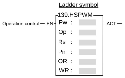
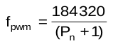 While Rs (Resolution)=1/100
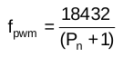 While Rs (Resolution)=1/1000
7-16-4 High Speed Pulse Output Instruction
|
FUN140 HSPSO |
HIGH SPEED PULSE OUTPUT INSTRUCTION |
FUN140 HSPSO |
|||||||||||||||||||||||||
|
Symbol |
|||||||||||||||||||||||||||
|
|
Ps : The set number of Pulse Output (0~7) 0:Y0 & Y1 1:Y2 & Y3 2:Y4 & Y5 3:Y6 & Y7 4:MQ Y16 & Y17, Y8 & Y9 otherwise 5:MQ Y18 & Y19, Y10 & Y11 otherwise 6:MQ Y20 & Y21, Y12 & Y13 otherwise 7:MQ Y22 & Y23, Y14 & Y15 otherwise SR: Starting register for positioning program WR: Starting register for instruction operation controls 7 registers, which the other program cannot repeat in using. |
||||||||||||||||||||||||||
|
|||||||||||||||||||||||||||
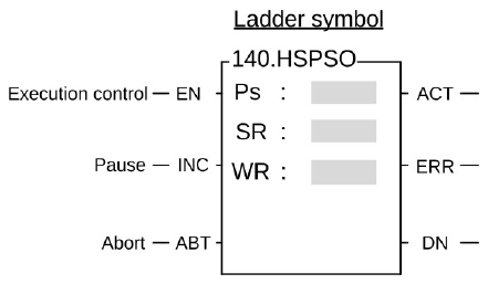
|
FUN140 HSPSO |
HIGH SPEED PULSE OUTPUT INSTRUCTION |
FUN140 HSPSO |
|
Description |
||
|
||
7-16-5 Positioning program parameter setting command (MPARA)
|
FUN141 MPARA |
MPARA |
FUN141 MPARA |
||||||||||||||||||||||||||||
|
Symbol |
||||||||||||||||||||||||||||||
|
|
Ps: Group of Pulse output (0~7) SR: Parameter table starting register, 18 parameters in total, occupying 24 registers |
|||||||||||||||||||||||||||||
|
||||||||||||||||||||||||||||||
|
Description |
||||||||||||||||||||||||||||||
|
||||||||||||||||||||||||||||||
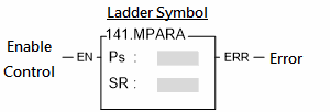
|
FUN141 MPARA |
MPARA |
FUN141 MPARA |
||||||||||||||||||||||||||||||||||||||||||||||||||||||||||||||||||||||||||||||||||||||||||||
|
||||||||||||||||||||||||||||||||||||||||||||||||||||||||||||||||||||||||||||||||||||||||||||||
|
FUN141 MPARA |
MPARA |
FUN141 MPARA |
|
Use UperLogic to edit the servo parameter table In the project window, click the servo parameter table: Project Name Table Edit Servo Parameter Table After right-clicking, click "Add Servo Parameter Table".
|
||

|
Parameter Description
□When the setting value is 0, the travel and speed setting values used in the program are specified in mm, Deg, Inch as the unit, which is called the mechanical unit. □When the setting value is 1, the travel and speed setting values used in the program are all specified in the unit of Pulse, which is called the motor unit. □When the setting value is 2, the stroke setting values used in the program are all specified in mm, Deg, Inch as the unit, and the speed setting is all specified in Pulse as the unit, which is called compound unit.
|
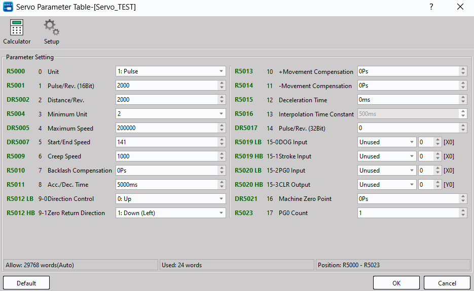
|
FUN141 MPARA |
MPARA |
FUN141 MPARA |
||||||||||||||||||||||||||||
The number of pulses required for one revolution of the motor (A) A=1~65535 (when it is above 32767, set it as a decimal positive number) Ps/Rev When parameter 14 = 0, take parameter 1 as pulse number/1 revolution. When parameter 14 ≠ 0, take parameter 14 as pulse number/1 revolution.
B=1~999999 M/Rev 1~999999 mDeg/Rev 1~999999×0.1 mInch/Rev
|
||||||||||||||||||||||||||||||
|
FUN141 MPARA |
MPARA |
FUN141 MPARA |
□Motor and compound unit: 1~200000 Ps/Sec □Mechanical unit: 1~153000 (cm/Min, x10 Deg/Min, Inch/Min) But the highest frequency can not be greater than 200000 Ps/Sec f_max =(V_max x 1000 x A)/(6 x B)200000 Ps/Sec f_min 1 Ps/Sec Note: A=parameter 1, B=parameter 2
□Motor and compound unit: 1~200000 Ps/Sec □Mechanical unit: 1~15300(cm/Min,10 Deg/Min,Inch/Min) But the highest frequency cannot be greater than 200000 Ps/Sec。
Motor and compound unit: 1~65535 Ps/Sec Mechanical unit: 1~15300 (Cm/Min, x10 Deg/Min, Inch/Min)
Note: Multi-axis linear interpolation command is invalid Setting range: 0~32767 Ps。 When walking in reverse, the walking distance will automatically add this value. |
||
|
FUN141 MPARA |
MPARA |
FUN141 MPARA |
|||||||||
Note: Multi-axis linear interpolation command is invalid Setting range: 0~30000 mS. This time represents the time required to accelerate from rest to maximum speed (parameter 4), or decelerate from maximum speed to rest. The acceleration and deceleration of this system is equal slope control. When parameter 12=0, this parameter is used as the deceleration time. The acceleration and deceleration control of this system will automatically move in a triangle wave or trapezoid wave according to the actual action stroke.
Note: Multi-axis linear interpolation command is invalid
When the set value = 0, the forward rotation pulse output, the current Ps value will increase Reverse the pulse output, the current Ps value will decrease When the set value = 1, the forward rotation pulse output, the current Ps value will decrease Reverse the pulse output, and increase the current Ps value
When the set value is 0, the homing direction is the current Ps value plus the upward direction (the origin is on the right) When the set value = 1, the direction of homing is the direction of decreasing the current Ps value (the origin is on the left)
Note: Multi-axis linear interpolation command is invalid Setting range: 32768~32767 Ps
Setting range:-32768~32767 Ps
|
|||||||||||
Note: The multi-axis linear interpolation command is invalid
Note: Multi-axis line tweening command is dedicated
b6~b0 : Proximity DOG input contact number (0~15, namely X0~X15) b7 = 0: Near-point DOG input is a normally open contact (A or NO contact) = 1: The near-point DOG input is a normally closed contact (B or NC contact) b7~b0=FFH, no near-point DOG input
b14~b8 : Travel limit input contact number (0~125, namely X0~X125) b15 = 0: Travel limit input is a normally open contact (A or NO contact) = 1: Travel limit input is a normally closed contact (B or NC contact) b15~b8=FFH : No stroke limit input |
|||||||||||
|
FUN141 MPARA |
MPARA |
FUN141 MPARA |
|||||||||
b6~b0 : Zero signal PG0 input contact number (0~15, namely X0~X15) b7 = 0 : The leading edge of near point DOG starts to count the zero point signal = 1 : The trailing edge of the near point DOG starts to count the zero signal b7~b0 = FFH : No zero signal PG0 input
b15~b8 : Output contact number of zero reset signal CLR (0~23, that is, Y0~Y23) b15~b8=FFH : CLR output without reset signal
-999999~999999 Ps
|
|||||||||||
 0~255 Count
7-16-6 STOP THE HSPSO PULSE OUTPUT (PSOFF)
|
FUN142 P PSOFF |
STOP THE HSPSO PULSE OUTPUT |
FUN142 P PSOFF |
|||||||
|
Symbol |
|||||||||
|
|
N: 0~7 Enforce the Pulse Output PSOn (n= Ps) to stop |
|
|||||||
|
Description |
|||||||||
|
|||||||||
|
Example |
|||||||||
|
|||||||||

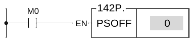
7-16-7 Convert The Current Pulse Value to Display Value(PSCNV)
|
FUN143 P PSCNV |
CONVERT THE CURRENT PULSE VALUE TO DISPLAY VALUE (mm, Deg, Inch, PS) |
FUN143 P PSCNV |
||||||||||||||||||||
|
Symbol |
||||||||||||||||||||||
|
|
Ps : 0~3; it converts the number of the pulse position to be the mm (Deg, Inch, PS) that has same unit as the set value, so as to make current position displayed. D : Register that stores the current position after conversion. It uses 2 registers, e.g. if D = D10, which means D10 is Low Word and D11 is High Word. |
|||||||||||||||||||||
|
||||||||||||||||||||||
|
Description |
||||||||||||||||||||||
|
||||||||||||||||||||||
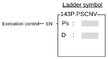
|
FUN143 P PSCNV |
CONVERT THE CURRENT PULSE VALUE TO DISPLAY VALUE (mm, Deg, Inch, PS) |
FUN143 P PSCNV |
||||
|
Example |
||||||
When M0 changes from 0 to 1, convert the current pulse wave position of Ps0 (DR4088) into mm (or Deg or Inch or PS) with the same unit as the set value, and store it in DD10 as the current position display. |
||||||
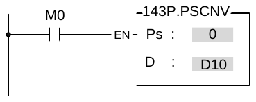
7-16-8 HIGH SPEED PULSE WIDTH MODULATION 2
|
FUN144 HSPWM2 |
HIGH SPEED PULSE WIDTH MODULATION 2 |
FUN144 HSPWM2 |
||||||||||||||||||||||||||||||||||||||||||||||||||||||||||||||||||||||||||||||||||||||||||
|
Symbol |
||||||||||||||||||||||||||||||||||||||||||||||||||||||||||||||||||||||||||||||||||||||||||||
|
|
PW:Output of pulse width modulation 0:Y0 & Y1 1:Y2 & Y3 2:Y4 & Y5 3:Y6 & Y7 4:MQ Y16 & Y17, Y8 & Y9 otherwise 5:MQ Y18 & Y19, Y10 & Y11 otherwise 6:MQ Y20 & Y21, Y12 & Y13 otherwise 7:MQ Y22 & Y23, Y14 & Y15 otherwise Op:Output polarity (0=positive phase, 1=negative phase) Hz:Output frequency (1~100000000 or 1~200000000, unit: 0.001Hz) OR:Width of output pulse (0~100, unit: %) |
|||||||||||||||||||||||||||||||||||||||||||||||||||||||||||||||||||||||||||||||||||||||||||
|
||||||||||||||||||||||||||||||||||||||||||||||||||||||||||||||||||||||||||||||||||||||||||||

|
FUN144 HSPWM2 |
HIGH SPEED PULSE WIDTH MODULATION 2 |
FUN144 HSPWM2 |
|
Description |
||
|
||
7-17 Enable/Disable (FUN145~146)
7-17-1 ENABLE CONTROL OF THE INTERRUPT AND PERIPHERAL
|
FUN145 P EN |
ENABLE CONTROL OF THE INTERRUPT AND PERIPHERAL |
FUN145 P EN |
||||||||||||||||||||||||||||||
|
Symbol |
||||||||||||||||||||||||||||||||
|
|
LBL : External input or peripheral label name that to be enabled. |
|||||||||||||||||||||||||||||||
|
||||||||||||||||||||||||||||||||
|
Description |
||||||||||||||||||||||||||||||||
|
||||||||||||||||||||||||||||||||
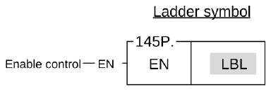
|
FUN145 P EN |
ENABLE CONTROL OF THE INTERRUPT AND PERIPHERAL |
FUN145 P EN |
||||||||||||||||||||||||||||||||||||||||||||||||||||||||||||||||||||||||||||||||||||
|
Description |
||||||||||||||||||||||||||||||||||||||||||||||||||||||||||||||||||||||||||||||||||||||
|
||||||||||||||||||||||||||||||||||||||||||||||||||||||||||||||||||||||||||||||||||||||
|
FUN145 P EN |
ENABLE CONTROL OF THE INTERRUPT AND PERIPHERAL |
FUN145 P EN |
||||||||||||||||||||||||||||||||||||||||||||||||||||||||||||||||||||||||||||||||||||
|
Description |
||||||||||||||||||||||||||||||||||||||||||||||||||||||||||||||||||||||||||||||||||||||
|
||||||||||||||||||||||||||||||||||||||||||||||||||||||||||||||||||||||||||||||||||||||
|
FUN145 P EN |
ENABLE CONTROL OF THE INTERRUPT AND PERIPHERAL |
FUN145 P EN |
||||||||||||||||||||||||||||||||||||||||||||||||||||||||||||||||||||||||||||||||||||
|
||||||||||||||||||||||||||||||||||||||||||||||||||||||||||||||||||||||||||||||||||||||
|
Example |
||||||||||||||||||||||||||||||||||||||||||||||||||||||||||||||||||||||||||||||||||||||
|
||||||||||||||||||||||||||||||||||||||||||||||||||||||||||||||||||||||||||||||||||||||
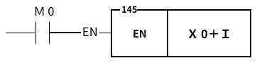
7-17-2 DISABLE CONTROL OF THE INTERRUPT AND PERIPHERAL
|
FUN146 P DIS |
DISABLE CONTROL OF THE INTERRUPT AND PERIPHERAL |
FUN146 P DIS |
||||||||||||||||||||||||||||||
|
Symbol |
||||||||||||||||||||||||||||||||
|
|
LBL : Interrupt label intended to disable or peripheral name to be disabled. |
|||||||||||||||||||||||||||||||
|
||||||||||||||||||||||||||||||||
|
Description |
||||||||||||||||||||||||||||||||
|
||||||||||||||||||||||||||||||||
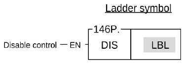
|
FUN146 P DIS |
DISABLE CONTROL OF THE INTERRUPT AND PERIPHERAL |
FUN146 P DIS |
||||
|
||||||
|
Example |
||||||
|
||||||

7-18 NC Positioning Instructions II (FUN147~149)
7-18-1 Multi-Axis High Speed Pulse Output
|
FUN147 MHSPO |
Multi-Axis High Speed Pulse Output |
FUN147 MHSPO |
|||||||||||||||||||||||||||||||||||
|
Symbol |
|||||||||||||||||||||||||||||||||||||
|
Ladder symbol
|
Gp: Group number (0~3) SR: Starting register for positioning program (example explanation) WR: Starting register for instruction operation (example explanation). It controls 9 registers, which the other program cannot repeat in using. |
||||||||||||||||||||||||||||||||||||
|
|||||||||||||||||||||||||||||||||||||
|
Description |
|||||||||||||||||||||||||||||||||||||
|
|||||||||||||||||||||||||||||||||||||
|
|||||||||||||||||||||||||||||||||||||
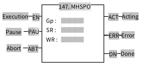
7-18-2 MANUAL PULSE GENERATOR FOR POSITIONING
|
FUN148 MPG |
MANUAL PULSE GENERATOR FOR POSITIONING |
FUN148 MPG |
|||||||||||||||||||||||||||||||||||
|
Symbol |
|||||||||||||||||||||||||||||||||||||
|
|
Sc: Source of high-speed counter; 0~7 Ps: Axis of pulse output; 0~3 Fo: Setting of output speed (2 registers) Mr: Setting of multipliers (2 registers) Mr+0: Multiplicand (Fa) Mr+1: Dividend (Fb) WR: Starting address of working registers, it needs 4 registers |
||||||||||||||||||||||||||||||||||||
|
|||||||||||||||||||||||||||||||||||||
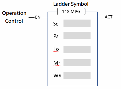
|
FUN148 MPG |
MANUAL PULSE GENERATOR FOR POSITIONING |
FUN148 MPG |
|
Description |
||
… |
||

|
FUN148 MPG |
MANUAL PULSE GENERATOR FOR POSITIONING |
FUN148 MPG |
||||
|
Example 1 |
||||||
|
||||||
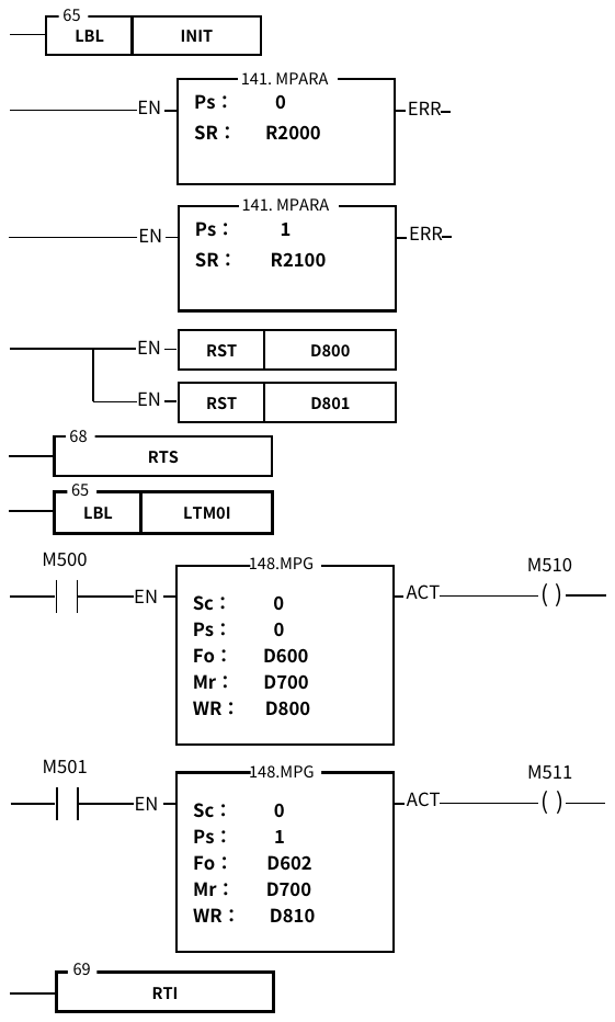
|
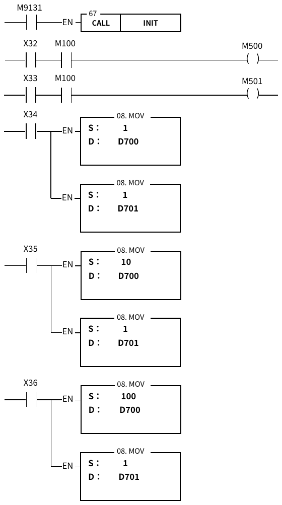
|
FUN148 MPG |
MANUAL PULSE GENERATOR FOR POSITIONING |
FUN148 MPG |
|
X32: Select the 0st axis (Ps0) X33: Select the 1st axis (Ps1) X34: output magnification is 1 X35: output magnification is 10 X36: output magnification is 100 M100: Manual wheel action selection DR2005: Maximum output frequency of axis 0 (parameter 4 of FUN141 command); 200K Hz R2011: Acceleration and deceleration time of the 0th axis (parameter 8 of the FUN141 instruction); 30mS DD600: 0th axis manual wheel actuation output frequency; 200K Hz DR2105: The maximum output frequency of the first axis (parameter 4 of the FUN141 command); 200K Hz R2111: Acceleration and deceleration time of the first axis (parameter 8 of FUN141 instruction); 30mS DD602: 1st axis manual wheel actuation output frequency; 200K Hz Example description: Put the manual wheel positioning processing instructions of Ps0 and Ps1 in the 50MSI timing interrupt processing program. When X32=1 and M100=1, start Ps0 hand wheel positioning processing; each interval (50mS) will sample the hand wheel input pulse (from HSC0); if no pulse input is sampled, FUN148 The command will not output; if there is a sampled pulse wave input, the output pulse number will be calculated according to the multiplier setting (D700 and D701), and then the calculated output pulse number will be output at the output frequency set by DD600. Output pulse number = (HSC0 input pulse number in interval time×D700)/D701 |
||
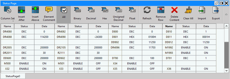
|
FUN148 MPG |
MANUAL PULSE GENERATOR FOR POSITIONING |
FUN148 MPG |
||||
|
Example 2 |
||||||
|
||||||
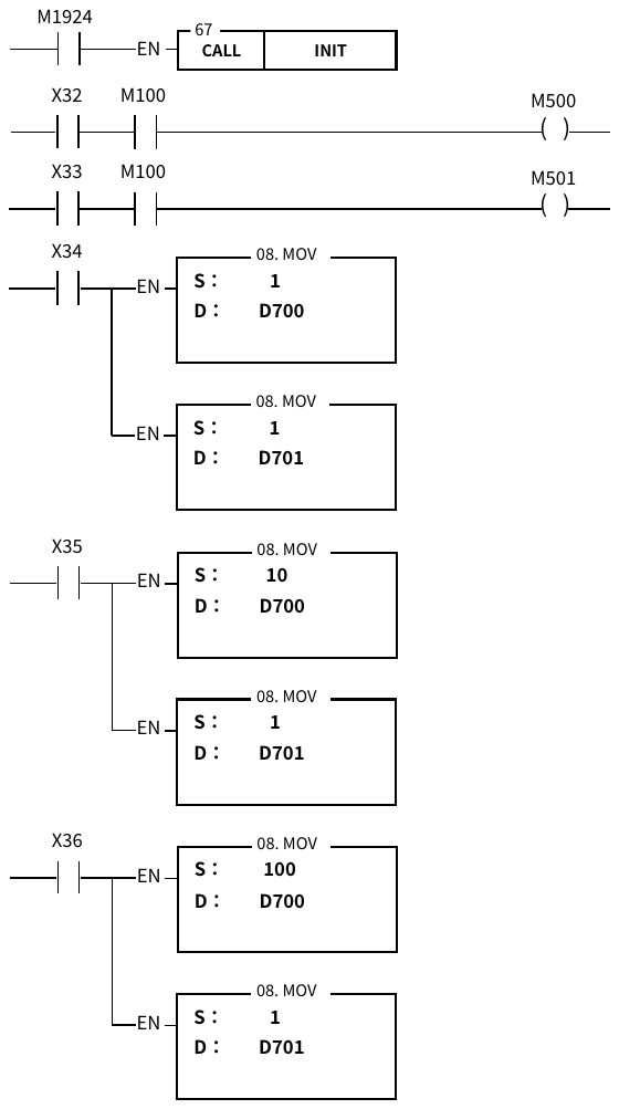
|

|
FUN148 MPG |
MANUAL PULSE GENERATOR FOR POSITIONING |
FUN148 MPG |
|
X33: Select the 1st axis (Ps1) X34: output magnification is 1 X35: output magnification is 10 X36: output magnification is 100 M100: Manual wheel action selection DR2005: Maximum output frequency of axis 0 (parameter 4 of FUN141 command); 200K Hz R2011: Acceleration and deceleration time of the 0th axis (parameter 8 of the FUN141 instruction); 30mS DD600: 0th axis manual wheel actuation output frequency; 200K Hz DR2105: The maximum output frequency of the first axis (parameter 4 of the FUN141 command); 200K Hz R2111: Acceleration and deceleration time of the first axis (parameter 8 of FUN141 instruction); 30mS DD602: 1st axis manual wheel actuation output frequency; 200K Hz Example description: Set the 0.1mS high-speed timer (HSTA) as a 50mS timer interrupt, and put the manual wheel positioning processing instructions of Ps0 and Ps1 in the HSTAI interrupt processing program. When X33=1 and M100=1, start Ps1 hand wheel positioning processing; each interval (50mS) will sample the hand wheel input pulse (from HSC0); if no pulse input is sampled, FUN148 There will be no output for the command; if there is a sampled pulse wave input, the output pulse number will be calculated according to the multiplier setting (D700 and D701), and then the calculated output pulse number will be output at the output frequency set by DD602. Output pulse number = (HSC0 input pulse number in interval time×D700)/D701 |
||
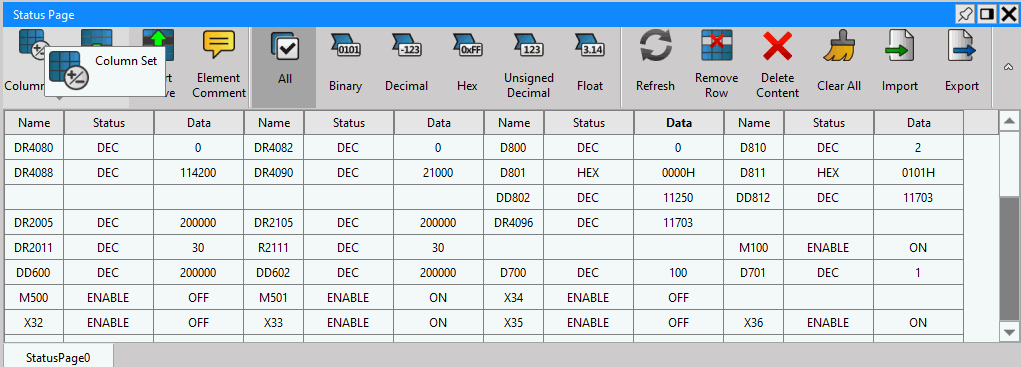
7-18-3 Arc High Speed Pulse Output
|
FUN149 AHSPO |
Arc High Speed Pulse Output |
FUN149 AHSPO |
||||||||||||||||||||||||||||||||||||||||||||||||||||||||
|
Symbol |
||||||||||||||||||||||||||||||||||||||||||||||||||||||||||
|
Ladder symbol
|
SR: Start Address of Register for Positioning Process. WR: Working Address of Register for Operating. |
|||||||||||||||||||||||||||||||||||||||||||||||||||||||||
|
||||||||||||||||||||||||||||||||||||||||||||||||||||||||||
|
Description |
||||||||||||||||||||||||||||||||||||||||||||||||||||||||||
|
||||||||||||||||||||||||||||||||||||||||||||||||||||||||||
|
||||||||||||||||||||||||||||||||||||||||||||||||||||||||||
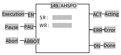
7-19 Communication Instruction (FUN150~156)
7-19-1 MODBUS MASTER INSTRUCTION(M-BUS)
|
FUN150 M-BUS |
MODBUS MASTER INSTRUCTION (WHICH MAKES PLC AS THE MODBUS MASTER THROUGH PORT 1~2) |
FUN150 M-BUS |
|||||||||||||||||||||||||||||||||||
|
Symbol |
|||||||||||||||||||||||||||||||||||||
|
|
Pt :1~4, specify the communication port being acted as the Modbus master SR:Starting register of communication program WR : Starting register for instruction operation. It controls 8 registers, the other programs can not repeat in using. |
||||||||||||||||||||||||||||||||||||
|
|||||||||||||||||||||||||||||||||||||
|
Description |
|||||||||||||||||||||||||||||||||||||
|
|||||||||||||||||||||||||||||||||||||
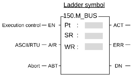
|
FUN150 M-BUS |
MODBUS MASTER INSTRUCTION (WHICH MAKES PLC AS THE MODBUS MASTER THROUGH PORT 1~2) |
FUN150 M-BUS |
|
Description |
||
|
7-19-2 COMMUNICATION LINK INSTRUCTION (CLINK)
|
FUN151 CLINK |
COMMUNICATION LINK INSTRUCTION (WHICH MAKES PLC ACT AS THE MASTER STATION IN CPU LINK NETWORK THROUGH PORT 1~4) |
FUN151 CLINK |
||||||||||||||||||||||||||||||||||||||||||
|
Symbol |
||||||||||||||||||||||||||||||||||||||||||||
|
|
Pt: Assign the port, 1~4 MD: Communication mode, MD0~MD5 #MD3 is only for Port2. SR: Starting register of communication table WR: Starting register for instruction operation. It controls 8 register, the other programs can not repeat in using. |
|||||||||||||||||||||||||||||||||||||||||||
|
||||||||||||||||||||||||||||||||||||||||||||
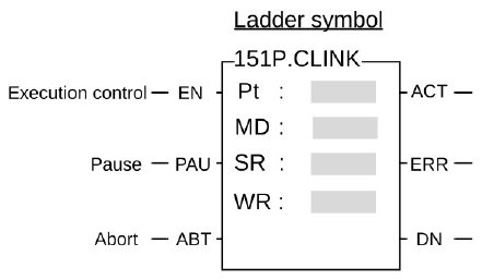
|
FUN151 CLINK |
COMMUNICATION LINK INSTRUCTION (WHICH MAKES PLC ACT AS THE MASTER STATION IN CPU LINK NETWORK THROUGH PORT 1~4) |
FUN151 CLINK |
|
Description |
||
|
||
7-19-3 Network Active Communication (NCR)
|
FUN152 NCR |
Network Active Communication |
FUN152 NCR |
||||||||||||||||||||||||||||||||||||||||||||||||||||||||||||||||||||||
|
Symbol |
||||||||||||||||||||||||||||||||||||||||||||||||||||||||||||||||||||||||
|
|
SR: Table starting register address MD: Modbus TCP active communication (=1,2) WR: Working register |
|||||||||||||||||||||||||||||||||||||||||||||||||||||||||||||||||||||||
|
||||||||||||||||||||||||||||||||||||||||||||||||||||||||||||||||||||||||
|
Description |
||||||||||||||||||||||||||||||||||||||||||||||||||||||||||||||||||||||||
|
||||||||||||||||||||||||||||||||||||||||||||||||||||||||||||||||||||||||
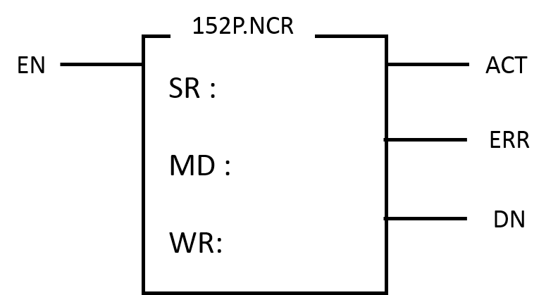
|
FUN152 NCR |
Network active communication |
FUN152 NCR |
||||
|
Example |
Slave Station (IP: 192.168.0.151) 400101~ 400105 -> Master Station (IP: 192.168.0.150) R100~R104 |
|||||
|
||||||
|
Description |
|
7-19-4 CMCTL
|
FUN156P CMCTL |
CMCTL |
FUN156P CMCTL |
||||||||||||||||||||||||||||||||||||||||||||||||||||||||
|
Symbol |
||||||||||||||||||||||||||||||||||||||||||||||||||||||||||
|
|
ID : Used module number Pt : Appointed COMA/COMB (A= 0;B=1) Ts : Communication table mask Bit 1 : Table 1 Bit 2 : Table 2 | Bit 15 : Table 15 Bit 16~Bit 31 : Reserved. Do not use. MD : Set mode 0 : RUN ONCE 1 : RUN CYCLING 2 : STOP WR : Saving operations state Bit0~Bit1 : Table 0 state Bit2~Bit3 : Table 1 state Bit30~Bit31 : Table 15 state = 0 : RUN_ONCE = 1 : RUN_CYCLING = 2 : STOP, |
|||||||||||||||||||||||||||||||||||||||||||||||||||||||||
|
||||||||||||||||||||||||||||||||||||||||||||||||||||||||||

|
FUN156P CMCTL |
CMCTL |
FUN156P CMCTL |
|||||||||||||||||||||||
|
Description |
|||||||||||||||||||||||||
|
Such command should be used with the CM25 and CM55 communication modules. Before each use, it is required to set up the communication module data.
FUN156:WR Description
Reserved after Bit32 |
|||||||||||||||||||||||||
|
FUN156P CMCTL |
CMCTL |
FUN156P CMCTL |
|||||
|
Example |
|||||||
As indicated in the figure above, when M0 becomes 1, the command will open Port 0 of the No. #0 module and then start the communication according to Table 1 and Table 2 (0001b+0010b=0011b and then 3(10) is obtained). Next, select RUN CYCLING Mode and then RO for use as the working register. |
|||||||
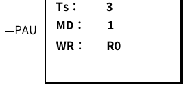
7-20 Data Movement Instructions (FUN160~162)
7-20-1 Read/Write File Register
|
FUN160D P RWFR |
Read/Write File Register |
FUN160D P RWFR |
||||||||||||||||||||||||||||||||||||||||||||||||||||||||||||||||||||||||||||||||||||||||||||||||||||||
|
Symbol |
||||||||||||||||||||||||||||||||||||||||||||||||||||||||||||||||||||||||||||||||||||||||||||||||||||||||
|
|
Sa : Starting address of data register Sb : Starting address of file register Pr : Record pointer register L : Quantity of register to form a record, 1~511 Sa operand can combine V、Z、P0~P9 for index addressing. |
|||||||||||||||||||||||||||||||||||||||||||||||||||||||||||||||||||||||||||||||||||||||||||||||||||||||
|
||||||||||||||||||||||||||||||||||||||||||||||||||||||||||||||||||||||||||||||||||||||||||||||||||||||||
|
Description |
||||||||||||||||||||||||||||||||||||||||||||||||||||||||||||||||||||||||||||||||||||||||||||||||||||||||
|
||||||||||||||||||||||||||||||||||||||||||||||||||||||||||||||||||||||||||||||||||||||||||||||||||||||||
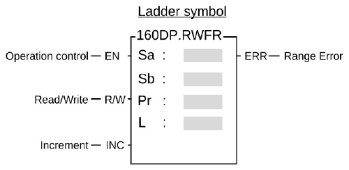
|
FUN160D P RWFR |
Read/Write File Register |
FUN160D P RWFR |
||||
|
|
||||||
|
Example 1 |
||||||
|
||||||
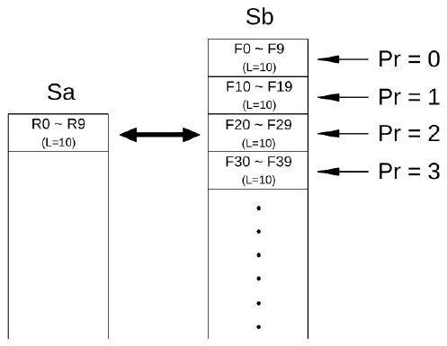
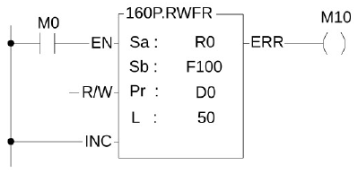
|
FUN160D P RWFR |
Read/Write File Register |
FUN160D P RWFR |
||||
|
Example 2 |
||||||
|
||||||
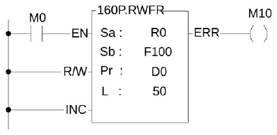
7-20-2 Write SD Card (WR-MP)
|
FUN161P WR-MP |
Write Data Record into the MEMORY_PACK (Write memory pack) |
FUN161P WR-MP |
||||||||||||||||||||||||||||||||||||||||||||||||||||||||||||||||||||||||
|
Symbol |
||||||||||||||||||||||||||||||||||||||||||||||||||||||||||||||||||||||||||
|
|
S:Starting address of the source data BK:Block number of the MEMORY_PACK,0~1 Os:Offset of the block Pr:Address of the pointer L:Quantity of writing,1~128 WR:Starting address of working registers, it takes 2 registers S may combine with V、Z、P0~P9 for indirect addressing application. |
|||||||||||||||||||||||||||||||||||||||||||||||||||||||||||||||||||||||||
|
||||||||||||||||||||||||||||||||||||||||||||||||||||||||||||||||||||||||||
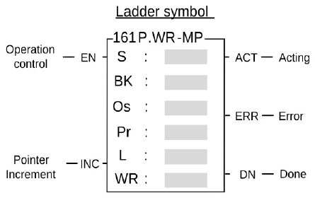
|
FUN161P WR-MP |
Write Data Record into the MEMORY_PACK (Write memory pack) |
FUN161 P WR-MP |
|
Description |
||
|
||

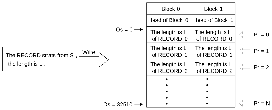
|
FUN161P WR-MP |
Write Data Record into the MEMORY_PACK (Write memory pack) |
FUN161P WR-MP |
||||
|
||||||
|
Example |
Writing the record into block 1 with the different length |
|||||
|
||||||
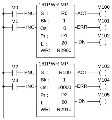
|
FUN161P WR-MP |
Write Data Record into the MEMORY_PACK (Write memory pack) |
FUN161P WR-MP |
|
|
||
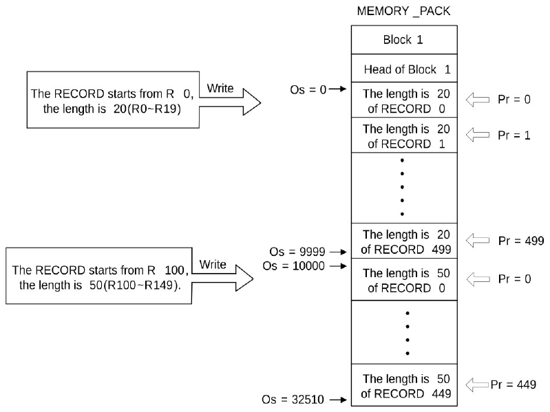
7-20-3 Read SD Card (RD-MP)
|
FUN162 P RD-MP |
Read Data Record from the MEMORY_PACK (Read memory pack) |
FUN162 P RD-MP |
|||||||||||||||||||||||||||||||||||||||||||||||||||||||||||||||
|
Symbol |
|||||||||||||||||||||||||||||||||||||||||||||||||||||||||||||||||
|
|
BK:Block number of the MEMORY_PACK,0~1 Os:Offset of the block Pr:Address of the pointer L:Quantity of reading,1~128 D:Starting address to store the reading record |
||||||||||||||||||||||||||||||||||||||||||||||||||||||||||||||||
|
|||||||||||||||||||||||||||||||||||||||||||||||||||||||||||||||||
|
Description |
|||||||||||||||||||||||||||||||||||||||||||||||||||||||||||||||||
The working diagram as shown below : |
|||||||||||||||||||||||||||||||||||||||||||||||||||||||||||||||||
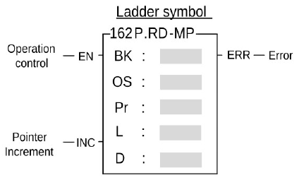
|
FUN162 P RD-MP |
Read Data Record from the MEMORY_PACK (Read memory pack) |
FUN162 P RD-MP |
|
|
||
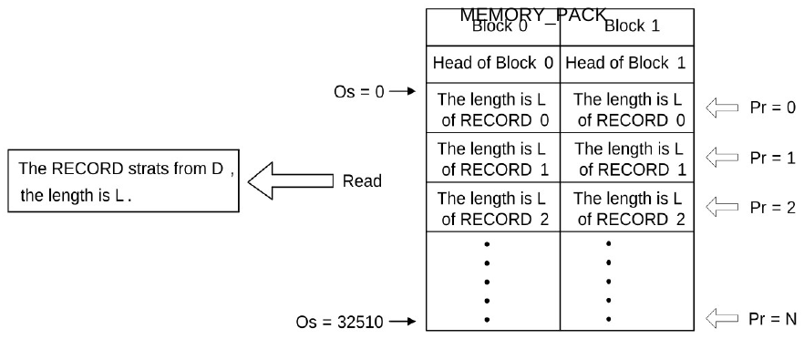
|
FUN162 P RD-MP |
Read Data Record from the MEMORY_PACK (Read memory pack) |
FUN162 P RD-MP |
||||
|
Example |
Reading the record from block 1 with the different length |
|||||
|
※ It is necessary that correct data in MEMORY_PACK or this example can’t execute correctly.
|
||||||
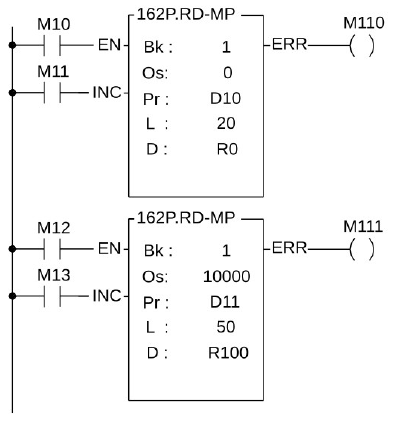
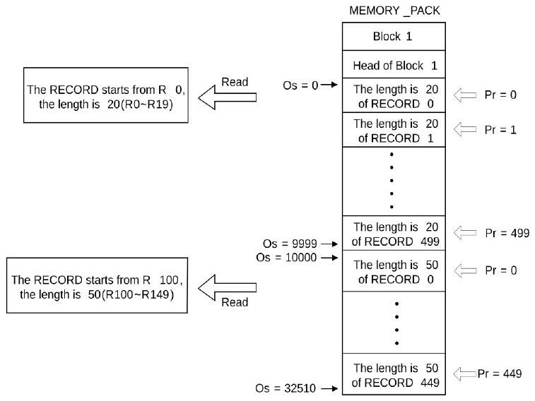
7-21 In Line Comparison Instruction (FUN170~175)
7-21-1 Equal To Compare
|
FUN170 D = |
EQUAL TO COMPARE (Compare whether Sa is equal to Sb) |
FUN170 D = |
|||||||||||||||||||||||||||||||||||||||||||||||||||||||||||||||||
|
Symbol |
|||||||||||||||||||||||||||||||||||||||||||||||||||||||||||||||||||
|
|
Sa:Operand A or the starting address of Sa Sb:Operand B or the starting address of Sb Sa、Sb may combine with V、Z、P0~P9 for indirect addressing application |
||||||||||||||||||||||||||||||||||||||||||||||||||||||||||||||||||
|
|||||||||||||||||||||||||||||||||||||||||||||||||||||||||||||||||||
|
Description |
|||||||||||||||||||||||||||||||||||||||||||||||||||||||||||||||||||
|
|||||||||||||||||||||||||||||||||||||||||||||||||||||||||||||||||||
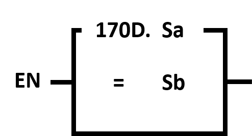
|
FUN170 D = |
EQUAL TO COMPARE (Compare whether Sa is equal to Sb) |
FUN170 D = |
||||
|
Example 1 |
||||||
Description: When R0=R2、R4=R6 and M0=1, the output status of Y0 is 1; otherwise it is 0. R0=R2、R8=R10 and M1=1, the output status of Y1 is 1; otherwise it is 0. |
||||||
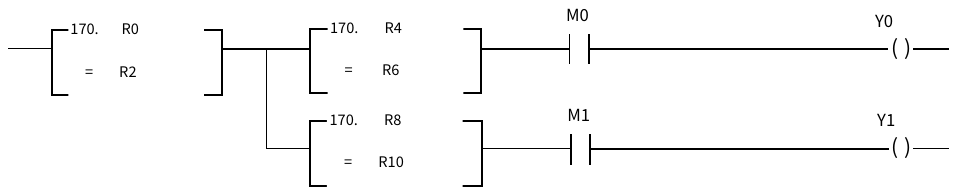
|
FUN170 D = |
EQUAL TO COMPARE (Compare whether Sa is equal to Sb) |
FUN170 D = |
||||
|
Example 2 |
||||||
Description: When DR600=DR602 or DR604>DR606, after them DR608<DR610 and DR616≧DR618, or DR612≠DR614 and DR620≦DR622, or M200=1and M201=1, and then M100=1, the output status of Y10 is 1; otherwise it is 0. |
||||||
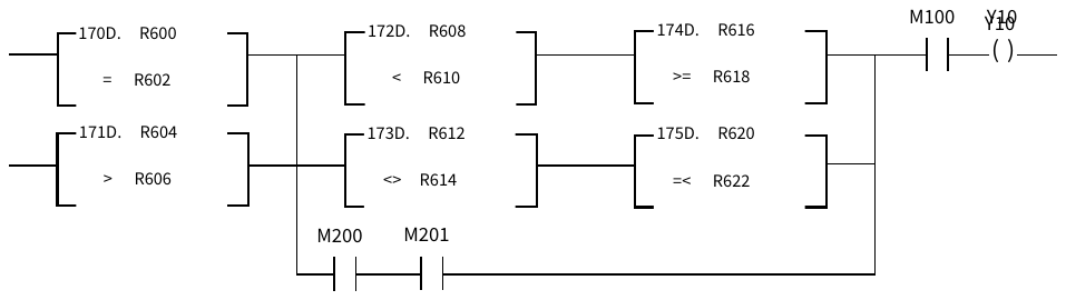
7-21-2 GREATER THAN COMPARE
|
FUN171 D > |
GREATER THAN COMPARE (Compare whether Sa is greater than Sb) |
FUN171 D > |
||||||||||||||||||||||||||||||||||||||||||||||||||||||||||||||||
|
Symbol |
||||||||||||||||||||||||||||||||||||||||||||||||||||||||||||||||||
|
|
Sa:Operand A or the starting address of Sa Sb:Operand B or the starting address of Sb Sa、Sb may combine with V、Z、P0~P9 for indirect addressing application |
|||||||||||||||||||||||||||||||||||||||||||||||||||||||||||||||||
|
||||||||||||||||||||||||||||||||||||||||||||||||||||||||||||||||||
|
Description |
||||||||||||||||||||||||||||||||||||||||||||||||||||||||||||||||||
|
||||||||||||||||||||||||||||||||||||||||||||||||||||||||||||||||||
|
Example 1 |
||||||||||||||||||||||||||||||||||||||||||||||||||||||||||||||||||
Description: When M10=1、R20 > R22 or M11=1, the output status of Y2 is 1; otherwise it is 0. |
||||||||||||||||||||||||||||||||||||||||||||||||||||||||||||||||||
|
FUN171 D > |
GREATER THAN COMPARE (Compare whether Sa is greater than Sb) |
FUN171 D > |
||||||||||||||||||||||||||||||||||||||||||||||||||||||||||||||||
|
Example 2 |
||||||||||||||||||||||||||||||||||||||||||||||||||||||||||||||||||
Description: When DR600=DR602 or DR604>DR606, after them DR608<DR610 and DR616≧DR618, or DR612≠DR614 and DR620≦DR622, or M200=1and M201=1, and then M100=1, the output status of Y10 is 1; otherwise it is 0. |
||||||||||||||||||||||||||||||||||||||||||||||||||||||||||||||||||
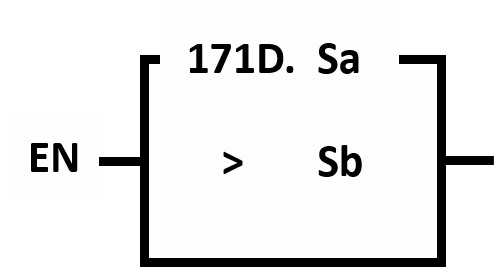

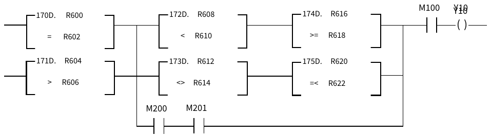
7-21-3 LESS THAN COMPARE
|
FUN172 D < |
LESS THAN COMPARE (Compare whether Sa is less than Sb) |
FUN172 D < |
||||||||||||||||||||||||||||||||||||||||||||||||||||||||||||||||
|
Symbol |
||||||||||||||||||||||||||||||||||||||||||||||||||||||||||||||||||
|
|
Sa:Operand A or the starting address of Sa Sb:Operand B or the starting address of Sb Sa、Sb may combine with V、Z、P0~P9 for indirect addressing application |
|||||||||||||||||||||||||||||||||||||||||||||||||||||||||||||||||
|
||||||||||||||||||||||||||||||||||||||||||||||||||||||||||||||||||
|
Description |
||||||||||||||||||||||||||||||||||||||||||||||||||||||||||||||||||
|
||||||||||||||||||||||||||||||||||||||||||||||||||||||||||||||||||

|
FUN172 D < |
LESS THAN COMPARE (Compare whether Sa is less than Sb) |
FUN172 D < |
||||
|
Example 1 |
||||||
Description: When M10=1、R20 < R22 or M11=1, the output status of Y2 is 1; otherwise it is 0. |
||||||

|
FUN172 D < |
LESS THAN COMPARE (Compare whether Sa is less than Sb) |
FUN172 D < |
||||
|
Example 2 |
||||||
Description: When DR600=DR602 or DR604>DR606, after them DR608<DR610 and DR616≧DR618, or DR612≠DR614 and DR620≦DR622, or M200=1and M201=1, and then M100=1, the output status of Y10 is 1; otherwise it is 0. |
||||||
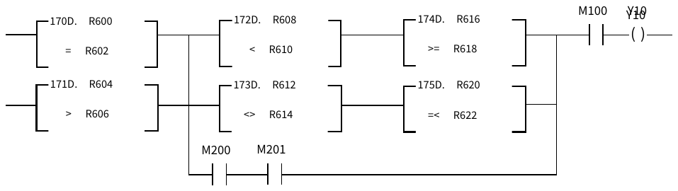
7-21-4 Not Equal To Compare
|
FUN173 D <> |
NOT EQUAL TO COMPARE (Compare whether Sa is not equal to Sb) |
FUN173 D <> |
|||||||||||||||||||||||||||||||||||||||||||||||||||||||||||||||||
|
Symbol |
|||||||||||||||||||||||||||||||||||||||||||||||||||||||||||||||||||
|
|
Sa:Operand A or the starting address of Sa Sb:Operand B or the starting address of Sb Sa、Sb may combine with V、Z、P0~P9 for indirect addressing application |
||||||||||||||||||||||||||||||||||||||||||||||||||||||||||||||||||
|
|||||||||||||||||||||||||||||||||||||||||||||||||||||||||||||||||||
|
Description |
|||||||||||||||||||||||||||||||||||||||||||||||||||||||||||||||||||
|
|||||||||||||||||||||||||||||||||||||||||||||||||||||||||||||||||||
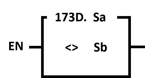
|
FUN173 D <> |
NOT EQUAL TO COMPARE (Compare whether Sa is not equal to Sb) |
FUN173 D <> |
||||
|
Example 1 |
When M10=1 and R20≠R22 or M11=1, the output Y2 is 1; otherwise it is 0. |
|||||
|
||||||

|
FUN173 D <> |
NOT EQUAL TO COMPARE (Compare whether Sa is not equal to Sb) |
FUN173 D <> |
||||
|
Example 2 |
||||||
Description: When DR600=DR602 or DR604>DR606, after them DR608<DR610 and DR616≧DR618, or DR612≠DR614 and DR620≦DR622, or M200=1and M201=1, and then M100=1, the output status of Y10 is 1; otherwise it is 0. |
||||||

7-21-5 GREATER THAN OR EQUAL TO COMPARE
|
FUN174 D >= |
GREATER THAN OR EQUAL TO COMPARE |
FUN174 D >= |
||||||||||||||||||||||||||||||||||||||||||||||||||||||||||||||||
|
Symbol |
||||||||||||||||||||||||||||||||||||||||||||||||||||||||||||||||||
|
|
Sa:Operand A or the starting address of Sa Sb:Operand B or the starting address of Sb Sa、Sb may combine with V、Z、P0~P9 for indirect addressing application. |
|||||||||||||||||||||||||||||||||||||||||||||||||||||||||||||||||
|
||||||||||||||||||||||||||||||||||||||||||||||||||||||||||||||||||
|
Description |
||||||||||||||||||||||||||||||||||||||||||||||||||||||||||||||||||
|
||||||||||||||||||||||||||||||||||||||||||||||||||||||||||||||||||
|
Example 1 |
When M10=1 and R20≧R22 or M11=1, the output Y2 is 1; otherwise it is 0. |
|||||||||||||||||||||||||||||||||||||||||||||||||||||||||||||||||
|
||||||||||||||||||||||||||||||||||||||||||||||||||||||||||||||||||
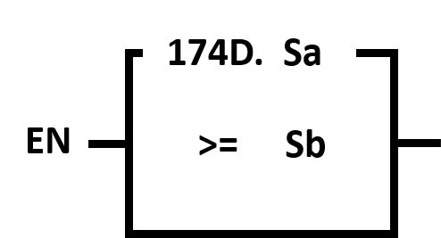

|
FUN174 D >= |
GREATER THAN OR EQUAL TO COMPARE |
FUN174 D >= |
||||
|
Example 2 |
||||||
Description: When DR600=DR602 or DR604>DR606, after them DR608<DR610 and DR616≧DR618, or DR612≠DR614 and DR620≦DR622, or M200=1and M201=1, and then M100=1, the output status of Y10 is 1; otherwise it is 0. |
||||||

7-21-6 LESS THAN OR EQUAL TO COMPARE
|
FUN175 D =< |
LESS THAN OR EQUAL TO COMPARE |
FUN175 D =< |
||||||||||||||||||||||||||||||||||||||||||||||||||||||||||||||||
|
Symbol |
||||||||||||||||||||||||||||||||||||||||||||||||||||||||||||||||||
|
|
Sa:Operand A or the starting address of Sa Sb:Operand B or the starting address of Sb Sa、Sb may combine with V、Z、P0~P9 for indirect addressing application. |
|||||||||||||||||||||||||||||||||||||||||||||||||||||||||||||||||
|
||||||||||||||||||||||||||||||||||||||||||||||||||||||||||||||||||
|
Description |
||||||||||||||||||||||||||||||||||||||||||||||||||||||||||||||||||
|
||||||||||||||||||||||||||||||||||||||||||||||||||||||||||||||||||

|
FUN175 D =< |
LESS THAN OR EQUAL TO COMPARE |
FUN175 D =< |
||||
|
Example 1 |
When M10=1 and R20≦R22 or M11=1, the output Y2 is 1; otherwise it is 0. |
|||||
|
||||||

|
FUN175 D =< |
LESS THAN OR EQUAL TO COMPARE |
FUN175 D =< |
|||||
|
Example 2 |
|||||||
Description: When DR600=DR602 or DR604>DR606, after them DR608<DR610 and DR616≧DR618, or DR612≠DR614 and DR620≦DR622, or M200=1and M201=1, and then M100=1, the output status of Y10 is 1; otherwise it is 0. |
|||||||
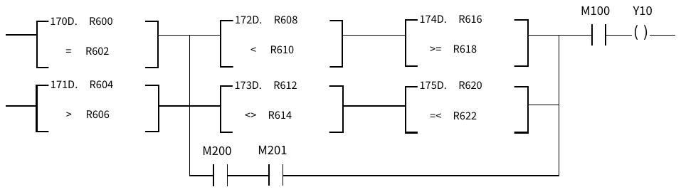
7-22 Motion Control Instructions
7-22-1 Running motion process (MFFlowStart)
|
FUN176 MFFlowStart |
Start motion process |
FUN176 MFFlowStart |
||||||||||||||||||||||||||||||||||||||||||||||
|
Symbol |
If different axes should be activated at the same time, do not use the ID repeatedly. |
|||||||||||||||||||||||||||||||||||||||||||||||
|
|
ID: The ID number of the motion process to be started. EN: = 1. Means the motion process defined by the command will be started. ACT: = 1. Means the system is running the defined motion process. ERR: = 1. Means error is found in the motion process. DN: =1. Means the motion process is completed. |
|||||||||||||||||||||||||||||||||||||||||||||||
|
||||||||||||||||||||||||||||||||||||||||||||||||
|
Example |
||||||||||||||||||||||||||||||||||||||||||||||||
|
||||||||||||||||||||||||||||||||||||||||||||||||
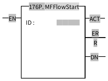

7-22-2 Stop all motion processes (MFSysStop)
|
FUN177 MFSysStop |
Stop all motion processes |
FUN177 MFSysStop |
|||||
|
Symbol |
|||||||
|
|
No operands |
||||||
|
Description |
|||||||
|
|||||||
|
Example |
|||||||
|
|||||||
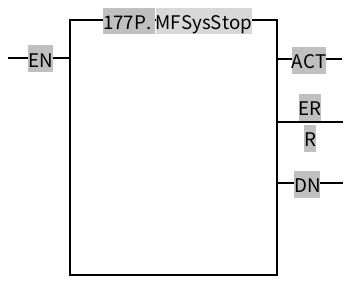
7-22-3 Home re-set (MFHome)
|
FUN178 MFHome |
Home re-set (MFHome) |
FUN178 MFHome |
||||||||||||||||
|
Symbol |
||||||||||||||||||
|
|
AX: Means the axis where the Home re-setting will be executed. |
|||||||||||||||||
|
Relay and Register
|
||||||||||||||||||
|
Description |
||||||||||||||||||
|
Specify the motion axis to perform homing.
Special register Axis 1: In return-to-origin operation M10621 Axis 1: Return to origin completed M10622 For the modes and details of the HOME command, please refer to Chapter 10. |
||||||||||||||||||
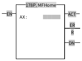
|
FUN178 MFHome |
Home re-set (MFHome) |
FUN178 MFHome |
||||
|
Example |
||||||
|
||||||
7-22-4 Position Control (MFPointMov)
|
Fun179 P MFPointMov |
Position Control (MFPointMov) |
Fun179 P MFPointMov |
|||||||||||||||||||||||||||||||||||||||||||||||||||||||||||||
|
Symbol |
|||||||||||||||||||||||||||||||||||||||||||||||||||||||||||||||
|
|
PT: Command number of motion point table AX: Motion control axis number |
||||||||||||||||||||||||||||||||||||||||||||||||||||||||||||||
|
Relay and Register
|
|||||||||||||||||||||||||||||||||||||||||||||||||||||||||||||||
|
Description |
|||||||||||||||||||||||||||||||||||||||||||||||||||||||||||||||
|
Execute the point table position control instruction.
Special registers:
|
|||||||||||||||||||||||||||||||||||||||||||||||||||||||||||||||
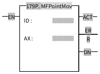
|
Fun179 P MFPointMov |
Position Control (MFPointMov) |
Fun179 P MFPointMov |
||||||||||||
|
Example |
||||||||||||||
However, if PT=2 and AX=1 was set, it will fail due to the difference from the point table setting, and ERR will be triggered.
|
||||||||||||||
7-22-5 JOG (MFJog)
|
Fun180 MFJog |
JOG (MFJog) |
Fun180 MFJog |
|||||||||||||||||||||||||||||||||||||||||||||||||||||||||||||
|
Symbol |
|||||||||||||||||||||||||||||||||||||||||||||||||||||||||||||||
|
|
AX: Means the axis where JOG action will be executed. MD: Mode of execution |
||||||||||||||||||||||||||||||||||||||||||||||||||||||||||||||
|
Relay and Register
|
|||||||||||||||||||||||||||||||||||||||||||||||||||||||||||||||
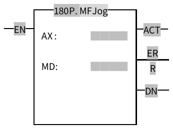
|
Fun180 MFJog |
JOG (MFJog) |
Fun180 MFJog |
|
Description |
||
|
According to the JOG parameter and mode setting, the specified motion axis executes the JOG function.
Mode 0: Continue to advance at the JOG start speed. Mode 1: Advance at JOG start speed, advance the jogging distance and then stop. Mode 2: Start at the JOG start speed, accelerate to the JOG speed with the JOG acceleration and continue moving forward. Mode 3: Start at the JOG start speed, accelerate to the JOG speed with the JOG acceleration, and stop after moving forward. Special registers
Please refer to Chapter 11 for JOG instruction modes and details. |
||
|
Fun180 MFJog |
JOG (MFJog) |
Fun180 MFJog |
||||||||||||||||
|
Example |
||||||||||||||||||
|
||||||||||||||||||
7-22-6 Change motion control parameters (MFChgTbPrm)
|
FUN181 MFChgTbPrm |
Change block parameters (MFChgTbPrm) |
FUN181 MFChgTbPrm |
||||||||||||||||||||||||||||||
|
Symbol |
||||||||||||||||||||||||||||||||
|
|
TM: Flow Block Table PN: The number of blocks S: Item Number PV: Written value |
|||||||||||||||||||||||||||||||
|
||||||||||||||||||||||||||||||||
|
Description |
||||||||||||||||||||||||||||||||
PN point number: Correspond to different types of numbers according to the table to be modified by TM, point table number, axis number, process block number. S item number: please refer to the table below PV write value: the value to be written, fixed Double Word.
|
||||||||||||||||||||||||||||||||
|
FUN181 MFChgTbPrm |
Change block parameters (MFChgTbPrm) |
FUN181 MFChgTbPrm |
||||||||||||||||||||||||||||||
|
Example |
||||||||||||||||||||||||||||||||
|
||||||||||||||||||||||||||||||||
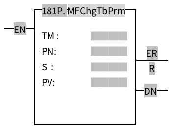
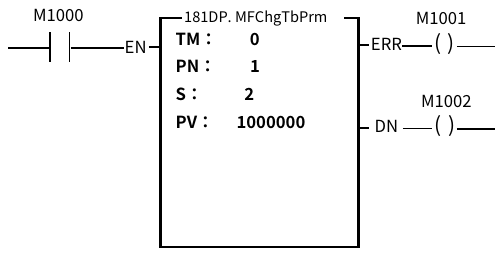
7-22-7 Pause Motion Flow (MFFlowPause)
|
FUN182 P MFFlowPause |
Pause Motion Flow (MFFlowPause) |
FUN182 P MFFlowPause |
||||||||||||||||||||||||||||||||||||||||||||||
|
Symbol |
||||||||||||||||||||||||||||||||||||||||||||||||
|
|
ID: The motion process to be paused. |
|||||||||||||||||||||||||||||||||||||||||||||||
|
Relay and Register
|
||||||||||||||||||||||||||||||||||||||||||||||||
|
Description |
||||||||||||||||||||||||||||||||||||||||||||||||
|
Pause the motion process of the specified ID, and stop after executing the current process block, To resume a paused motion process, you can use Fun183 MFFlowResume to resume execution.
|
||||||||||||||||||||||||||||||||||||||||||||||||
|
FUN182 P MFFlowPause |
Pause Motion Cycle (MFFlowPause) |
FUN182 P MFFlowPause |
||||||||||||||||||||||||||||||||||||||||||||||
|
Example |
||||||||||||||||||||||||||||||||||||||||||||||||
|
||||||||||||||||||||||||||||||||||||||||||||||||
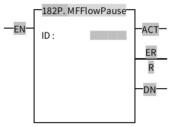
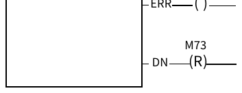
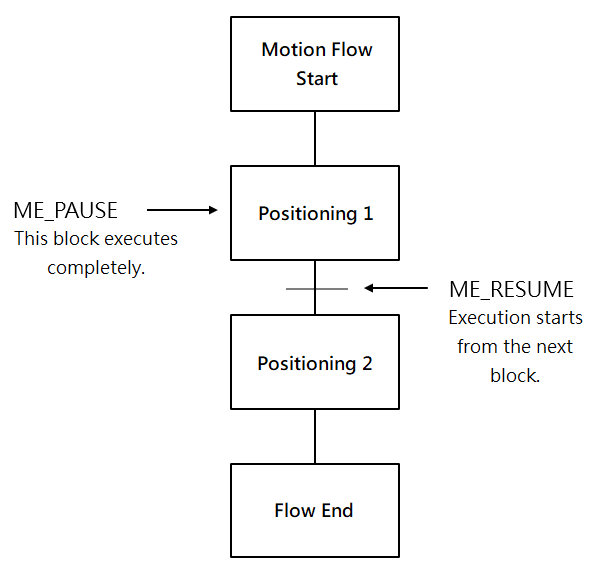
7-22-8 Resume Motion Process (MFFlowResume)
|
FUN183 P MFFlowResume |
Resume Motion Process (MFFlowResume) |
FUN183 P MFFlowResume |
||||||||||||||||||||||||||||||||||||||||||||||
|
Symbol |
||||||||||||||||||||||||||||||||||||||||||||||||
|
|
ID: Means the motion process to be resumed. |
|||||||||||||||||||||||||||||||||||||||||||||||
|
Relay and Register
|
||||||||||||||||||||||||||||||||||||||||||||||||
|
Description |
||||||||||||||||||||||||||||||||||||||||||||||||
|
Resume the paused or interrupted motion process and continue execution.
|
||||||||||||||||||||||||||||||||||||||||||||||||

|
FUN183 P MFFlowResume |
Resume Motion Process (MFFlowResume) |
FUN183 P MFFlowResume |
||||
|
Example |
||||||
|
||||||

7-22-9 Motion Process Halt (MFFlowHalt)
|
FUN184 P MFFlowHalt |
Motion Process Halt (MFFlowHalt) |
FUN184 P MFFlowHalt |
||||||||||||||||||||||||||||||||||||||||||||||
|
Symbol |
||||||||||||||||||||||||||||||||||||||||||||||||
|
|
ID: Means the motion process to be suspended. |
|||||||||||||||||||||||||||||||||||||||||||||||
|
Relay and Register
|
||||||||||||||||||||||||||||||||||||||||||||||||
|
Description |
||||||||||||||||||||||||||||||||||||||||||||||||
|
Immediately stops the currently executing process block, If you want to continue the stopped motion process, you can use Fun183 MFFlowResume to resume execution.
|
||||||||||||||||||||||||||||||||||||||||||||||||

|
FUN184 P MFFlowHalt |
Suspend Motion Process (MFFlowHalt) |
FUN184 P MFFlowHalt |
||||
|
Example |
||||||
|
||||||

7-22-10 Reset Motion Alarm (MFSysRstAlm)
|
FUN185 P MFSysRstAlm |
Reset Motion Alarm (MFSysRstAlm) |
FUN185 P MFSysRstAlm |
|
|
Symbol |
|||
|
|
|||
|
Description |
|||
|
Clears all motion sequences and driver error alerts; however, the communication alarm of the drive cannot be cleared by this command and needs to be powered on again.
|
|||
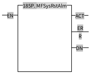
|
FUN185 P MFSysRstAlm |
Reset Motion Alarm (MFSysRstAlm) |
FUN185 P MFSysRstAlm |
||||
|
Example |
||||||
|
||||||
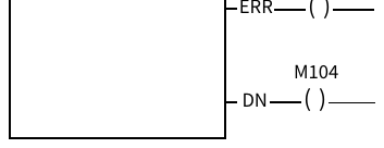
7-22-11 Motion Process Terminate (MFFlowStop)
|
FUN186 P MFFlowStop |
Stop Motion Process (MFFlowStop) |
FUN186 P MFFlowStop |
||||||||||||||||||||||||||||||||||||||||||||||
|
Symbol |
||||||||||||||||||||||||||||||||||||||||||||||||
|
Ladder
|
ID: ID number for the motion process to be finished. |
|||||||||||||||||||||||||||||||||||||||||||||||
|
Relay and Register
|
||||||||||||||||||||||||||||||||||||||||||||||||
|
Description |
||||||||||||||||||||||||||||||||||||||||||||||||
|
Immediately end the motion process of the specified ID. When execution of this instruction is complete, MFFlowResume cannot be used to resume execution. Need to use MFFlowStart to restart the process.
|
||||||||||||||||||||||||||||||||||||||||||||||||
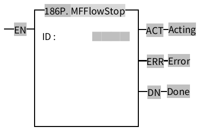
|
FUN186 P MFFlowStop |
Stop Motion Process (MFFlowStop) |
FUN186 P MFFlowStop |
||||
|
Example |
||||||
|
||||||
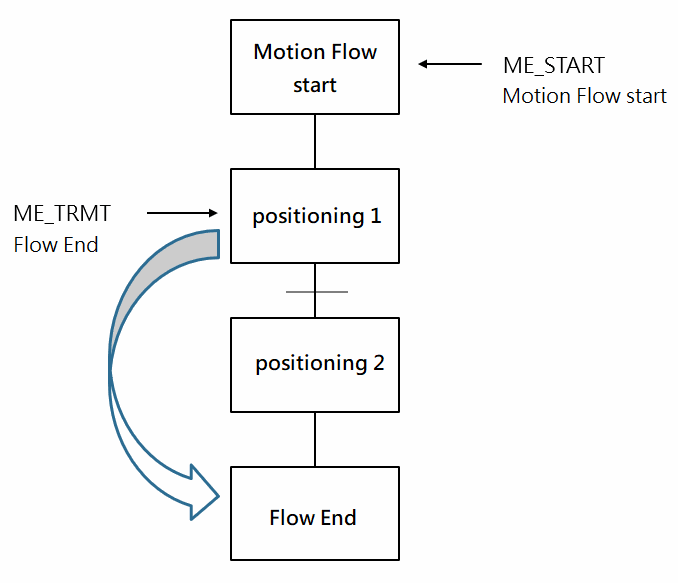
7-22-12 Servo Initialization (MFSysInit)
|
FUN187 P MFSysInit |
Servo Initialization |
FUN187 P MFSysInit |
|
|
Symbol |
|||
|
|
No operands |
||
|
Description |
|||
|
|||
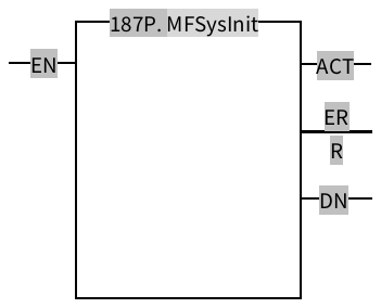
|
FUN187 P MFSysInit |
Servo Initialization |
FUN187 P MFSysInit |
||||
|
Example |
||||||
|
||||||
7-22-13 Recipe Reading (MFSysRCPR)
|
FUN188 P MFSysRCPR |
Recipe Reading (MFSysRCPR) |
FUN188 P MFSysRCPR |
||||||||||||||||||||||||||||||||||||||||||||||||||||||||||||||||||||||||||||
|
Symbol |
||||||||||||||||||||||||||||||||||||||||||||||||||||||||||||||||||||||||||||||
|
|
Md: 0, read parameters from PLC D: The starting position of the data register for moving into the mapping table GP: Recipe tables number, starting from 1 |
|||||||||||||||||||||||||||||||||||||||||||||||||||||||||||||||||||||||||||||
|
||||||||||||||||||||||||||||||||||||||||||||||||||||||||||||||||||||||||||||||
|
Description |
||||||||||||||||||||||||||||||||||||||||||||||||||||||||||||||||||||||||||||||
|
||||||||||||||||||||||||||||||||||||||||||||||||||||||||||||||||||||||||||||||
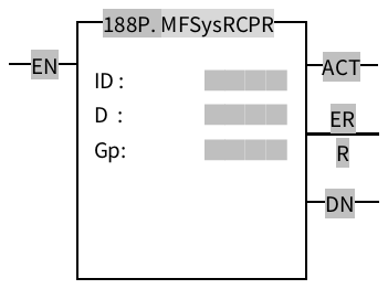
|
Recipe Table 【Project Management】>【Motion Control】>【Motion Recipe】
Tables: Point table, Axis table, Synchronization table Index: Point table (number of points), Axis table (number of axes), Synchronization table (number of axes) Length: Continuous point table or continuous axis Start address: The start address of the register for reading and writing recipes
Recipe Point Table
|
||||||||||||||||||||||||||||||||||||||||||||||||||||||||||||||||||||||||||||||||||||||||||||||||||||||||||||||||||||||||||||||||||||||||||||||||||||||||||||||||||||||||||||||||||||||||||||||||||||||||||||||||||||||||||||||||||||||||||||||||||||||||||||||||||||||||||||||||||||||||||||||||||||||||||||||||||||||||||||||||||||||||||||||||||||||||||||||||||||||||||||||||||||||||||||||||||||||||||||||||||||||||||||||||||||||||||||||||||||||||||||||||||||||||||||||||||||||||||||||||||||||||||||||||||||||||||||||||||||||||||||||||||||||||||||||||||||||||||||||||||||
|
Recipe Axis Table
|
||||||||||||||||||||||||||||||||||||||||||||||||||||||||||||||||||||||||||||||||||||||||||||||||||||||||||||||||||||||||||||||||||||||||||||||||||||||||||||||||||||||||||||||||||||||||||||||||||||||||||||||||||||||||||||||||||||||||||||||||||||||||||||||||||||||||||||||||||||||||||||||||||||||||||||||||||||||||||||||||||||||||||||||||||||||||||||||||||||||||||||||||||||||||||||||||||||||||||||||||||||||||||||||||||||||||||||||||||||||||||||||||||||||||||||||||||||||||||||||||||||||||||||||||||||||||||||||||||||||||||||||||||||||||||||||||||||||||||||||||||||
|
Recipe Synchronous Table
|
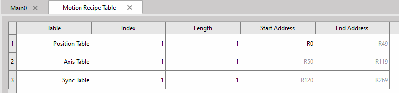
|
Example |
|||||
|
|||||
|
Motion Recipe Table
|
|||||
|
|||||
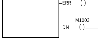

|
FUN188 P MFSysRCPR |
Motion Control Recipe Writing (MFSysRCPR) |
FUN188 P MFSysRCPR |
|
Example |
||
|
Find in “Project”-> “Motion recipe”
Take the target position of the point table as an example for mapping; the following figure is the setting page: The following is a sample program using the point table as an example: |
||

|
FUN188 P MFSysRCPR |
Motion Control Recipe Writing (BSysRCPR) |
FUN188 P MFSysRCPR |
||||
|
||||||
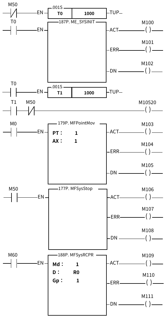
|
In this example, the motion control system will be initialized one second after the first execution, and the other axes will be Servo On after one second. When M60 is on, all contents of the midpoint table will be moved into recipe 1. Because R0 is the start register to be moved into the point table, then turn M0 ON to execute the point table, and its setting will follow the position of DR6. If you need to restore the recipe table before use, you can turn on the M50 and turn it off to restart the Motion control system. |
7-22-14 Motion Control Recipe Writing (MFSysRCPW)
|
FUN189 P MFSysRCPW |
Motion Control Recipe Writing (MFSysRCPW) |
FUN189 P MFSysRCPW |
||||||||||||||||||||||||||||||||||||||||||||||||||||||||||||||||||||||||||||
|
Symbol |
||||||||||||||||||||||||||||||||||||||||||||||||||||||||||||||||||||||||||||||
|
|
Md: 0, write parameters to PLC D: The starting position of the register for reading the mapping table data GP: Number of the recipe table, starting from 1 |
|||||||||||||||||||||||||||||||||||||||||||||||||||||||||||||||||||||||||||||
|
||||||||||||||||||||||||||||||||||||||||||||||||||||||||||||||||||||||||||||||
|
Description |
||||||||||||||||||||||||||||||||||||||||||||||||||||||||||||||||||||||||||||||
Md mode: 0 use PLC register D recipe starting register: the starting address of the register to be written into the recipe table Gp writes the column of the formula table: writes the column of the recipe table, 0 writes all
When the execution control [EN] is triggered by the lower differential, all output indications are reset
|
||||||||||||||||||||||||||||||||||||||||||||||||||||||||||||||||||||||||||||||

|
Recipe Table 【Project Management】>【Motion Control】>【Motion Recipe】
Tables: Point table, Axis table, Synchronization table Index: Point table (number of points), Axis table (number of axes), Synchronization table (number of axes) Length: continuous point table or continuous axis Start address: The start address of the register for reading and writing recipes
Recipe Point Table
|
||||||||||||||||||||||||||||||||||||||||||||||||||||||||||||||||||||||||||||||||||||||||||||||||||||||||||||||||||||||||||||||||||||||||||||||||||||||||||||||||||||||||||||||||||||||||||||||||||||||||||||||||||||||||||||||||||||||||||||||||||||||||||||||||||||||||||||||||||||||||||||||||||||||||||||||||||||||||||||||||||||||||||||||||||||||||||||||||||||||||||||||||||||||||||||||||||||||||||||||||||||||||||||||||||||||||||||||||||||||||||||||||||||||||||||||||||||||||||||||||||||||||||||||||||||||||||||||||||||||||||||||||||||||||||||||||||||||||||||||||||||
|
Recipe Axis Table
|
||||||||||||||||||||||||||||||||||||||||||||||||||||||||||||||||||||||||||||||||||||||||||||||||||||||||||||||||||||||||||||||||||||||||||||||||||||||||||||||||||||||||||||||||||||||||||||||||||||||||||||||||||||||||||||||||||||||||||||||||||||||||||||||||||||||||||||||||||||||||||||||||||||||||||||||||||||||||||||||||||||||||||||||||||||||||||||||||||||||||||||||||||||||||||||||||||||||||||||||||||||||||||||||||||||||||||||||||||||||||||||||||||||||||||||||||||||||||||||||||||||||||||||||||||||||||||||||||||||||||||||||||||||||||||||||||||||||||||||||||||||
|
Recipe Synchronous Table
|

|
FUN189 P MFSysRCPW |
Motion Control Recipe Writing (MFSysRCPW) |
FUN189 P MFSysRCPW |
||||
|
Example |
||||||
|
||||||

7-22-15 Cam Read (MFSysCAMR)
|
FUN191 P MFSysCAMR |
Motion Control Cam Read |
FUN191 P MFSysCAMR |
||||||||||||||||||||||||||||||||||||||||||||||||||||||||||||||||||||||||||||||||||||||||||
|
Symbol |
||||||||||||||||||||||||||||||||||||||||||||||||||||||||||||||||||||||||||||||||||||||||||||
|
|
Md: Mode D: Cam initial register ID: Cam number L: Cam resolution |
|||||||||||||||||||||||||||||||||||||||||||||||||||||||||||||||||||||||||||||||||||||||||||
|
||||||||||||||||||||||||||||||||||||||||||||||||||||||||||||||||||||||||||||||||||||||||||||
|
Description |
||||||||||||||||||||||||||||||||||||||||||||||||||||||||||||||||||||||||||||||||||||||||||||
|
Operands Md mode: 0 use PLC register D cam start register: The start address of the register to be stored after reading the cam ID cam number: Cam number L cam resolution: The length of the temporary register to be stored after reading the cam
When the execution control [EN] is triggered by the lower differential, all output indications are reset.
|
||||||||||||||||||||||||||||||||||||||||||||||||||||||||||||||||||||||||||||||||||||||||||||

|
Example |
|||||
CAM
Data Table
When M1000 is from OFF→ON, read the cam ID: 1 data table and store 2048 in DR1000~DR5094. |
|||||
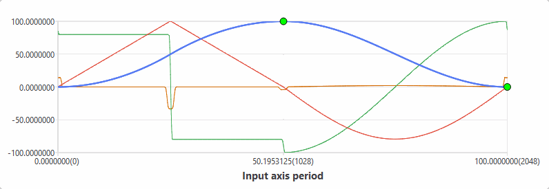
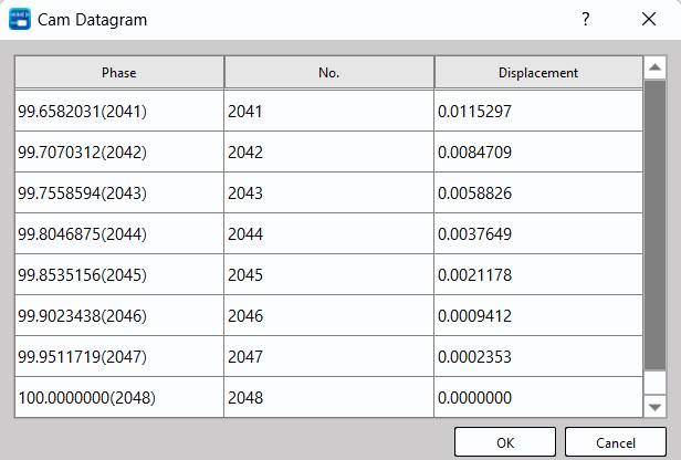
7-22-16 Cam Write (MFSysCAMW)
|
FUN192 P MFSysCAMW |
Motion Control Cam Write (MFSysCAMW) |
FUN192 P MFSysCAMW |
||||||||||||||||||||||||||||||||||||||||||||||||||||||||||||||||||||||||||||||||||||||||||
|
Symbol |
||||||||||||||||||||||||||||||||||||||||||||||||||||||||||||||||||||||||||||||||||||||||||||
|
|
Md: Mode D: Cam initial register ID: Cam number L: Cam resolution |
|||||||||||||||||||||||||||||||||||||||||||||||||||||||||||||||||||||||||||||||||||||||||||
|
Relay and Register
|
||||||||||||||||||||||||||||||||||||||||||||||||||||||||||||||||||||||||||||||||||||||||||||
|
Description |
||||||||||||||||||||||||||||||||||||||||||||||||||||||||||||||||||||||||||||||||||||||||||||
|
Operands Md mode: 0 use PLC register D cam start register: The start address of the register to be stored after reading the cam ID cam number: Cam number L cam resolution: The length of the temporary register to be stored after reading the cam
When the execution control [EN] is triggered by the lower differential, all output indications are reset.
|
||||||||||||||||||||||||||||||||||||||||||||||||||||||||||||||||||||||||||||||||||||||||||||
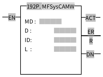
|
Example |
|||||||||
|
|||||||||
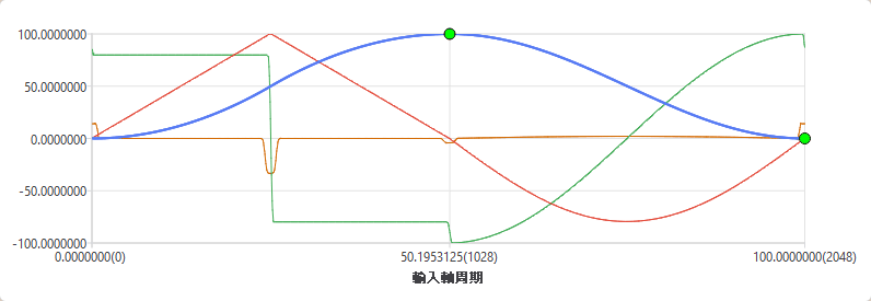
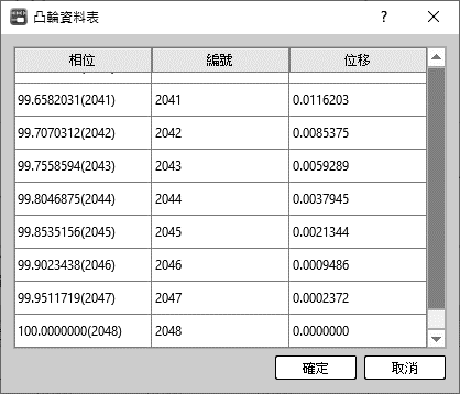
7-22-17 Handwheel (MFGearMPG)
|
FUN193 D P MFGearMPG |
Handwheel (MFGearMPG ) |
FUN193 D P MFGearMPG |
|||||||||||||||||||||||||||||||||||||||||||||||||||||||||||||||||||||||||||||||||||||||||||||||||||||||||
|
Symbol |
|||||||||||||||||||||||||||||||||||||||||||||||||||||||||||||||||||||||||||||||||||||||||||||||||||||||||||
|
|
Operand M: EtherCat spindle number S: EtherCat auxiliary shaft number N: Gear ratio numerator D: Gear ratio denominator T: Conversion time (in ms) |
||||||||||||||||||||||||||||||||||||||||||||||||||||||||||||||||||||||||||||||||||||||||||||||||||||||||||
|
Relay and Register
|
|||||||||||||||||||||||||||||||||||||||||||||||||||||||||||||||||||||||||||||||||||||||||||||||||||||||||||
|
Description |
|||||||||||||||||||||||||||||||||||||||||||||||||||||||||||||||||||||||||||||||||||||||||||||||||||||||||||
M spindle input source: EtherCAT_axis number 1~1 : Encoder_Gray code 100 (X8~X15) : Encoder_hardware high-speed counter number 101 ~ 104 (HSC4~HSC7 ) S slave axis output target: EtherCAT_axis number 1~16 ([M spindle input source] cannot be the same as [S slave axis output target]) |
|||||||||||||||||||||||||||||||||||||||||||||||||||||||||||||||||||||||||||||||||||||||||||||||||||||||||||

|
FUN193 D P MFGearMPG |
Handwheel (MFGearMPG ) |
FUN193 D P MFGearMPG |
N Variable gear ratio numerator: positive and negative numbers, including the [decimal point position] of the [motion axis setting] in the [motion control] ([Axis unit] set mm, [Decimal point position] set 0.001, N: DR0 = 1000 is equal to 1.000mm) D Variable gear ratio denominator: positive number (a real number greater than zero), including the [decimal point position] of [motion axis setting] in [motion control] T conversion time (ms): positive number (real number greater than zero), the unit is ms
When the execution control [EN] is triggered by the lower differential, Fun193 stops the synchronous control of the handwheel position and resets all output indicators.
|
||
|
FUN193 D P MFGearMPG |
Handwheel (MFGearMPG ) |
FUN193 D P MFGearMPG |
||||
|
Example |
||||||
Axis Parameter Setting
When M1000 is from OFF→ON, start the manual wheel synchronization according to the current Fun193 parameters (M: EtherCAT axis 1, N: EtherCAT axis 2, N: variable gear ratio numerator 0.001, D variable gear ratio denominator 0.001, T: 1ms). |
||||||
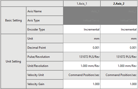
After changing the parameters (D variable gear ratio denominator 0.002), when M1005 is from OFF→ON, update the hand wheel according to the changed parameters. After the parameter update is completed, the output indication [UPD] is ON, and the stroke of the slave axis of the hand wheel is halved. |
7-22-18 Velocity Control Mode (MFVelCtl)
|
FUN194 D P MFVelCtl |
Velocity Control Mode (MFVelCtl) |
FUN194 D P MFVelCtl |
||||||||||||||||||||||||||||||||||||||||||||||||||||||||||||||||||||||||||||
|
Symbol |
||||||||||||||||||||||||||||||||||||||||||||||||||||||||||||||||||||||||||||||
|
|
S: Axis number V: Speed command MX: Maximum torque |
|||||||||||||||||||||||||||||||||||||||||||||||||||||||||||||||||||||||||||||
|
||||||||||||||||||||||||||||||||||||||||||||||||||||||||||||||||||||||||||||||
|
Description |
||||||||||||||||||||||||||||||||||||||||||||||||||||||||||||||||||||||||||||||
S speed control axis: EtherCAT_ axis number 1~16 V speed: speed setting value, unit Pulses/s MX maximum torque limit: when the speed cannot reach the speed setting value, the maximum torque limit, 0 equals no limit, unit 0.0%
When the execution control [EN] is triggered by the lower differential, Fun194 stops the axis speed control and resets all output indications
|
||||||||||||||||||||||||||||||||||||||||||||||||||||||||||||||||||||||||||||||
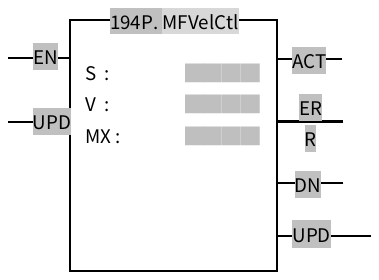
|
FUN194 D P MFVelCtl |
Velocity Control Mode (MFVelCtl) |
FUN194 D P MFVelCtl |
||||||||
|
Example |
||||||||||
|
||||||||||
7-22-19 Torque Control Mode (MFTorqCtl)
|
FUN195 D P MFTorqCtl |
Torque Control Mode (MFTorqCtl) |
FUN195 D P MFTorqCtl |
||||||||||||||||||||||||||||||||||||||||||||||||||||||||||||||||||||||||||||
|
Symbol |
||||||||||||||||||||||||||||||||||||||||||||||||||||||||||||||||||||||||||||||
|
|
S: Axis number V: Speed command MX: Maximum torque |
|||||||||||||||||||||||||||||||||||||||||||||||||||||||||||||||||||||||||||||
|
||||||||||||||||||||||||||||||||||||||||||||||||||||||||||||||||||||||||||||||
|
Description |
||||||||||||||||||||||||||||||||||||||||||||||||||||||||||||||||||||||||||||||
S torque control axis: EtherCAT_ axis number 1~16 T torque: Torque setting value, unit 0.0% MX Maximum speed limit: When the torque cannot reach the torque setting value, the maximum speed limit, 0 equals no limit, unit rpm
When the execution control [EN] is triggered by the lower differential, Fun195 stops the shaft torque control and resets all output indications
|
||||||||||||||||||||||||||||||||||||||||||||||||||||||||||||||||||||||||||||||
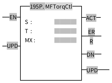
|
FUN195 D P MFTorqCtl |
Torque Control Mode (MFTorqCtl) |
FUN195 D P MFTorqCtl |
||||||||
|
Example |
||||||||||
|
||||||||||
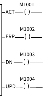
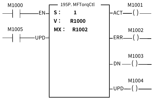
7-22-20 Cam Generate (MFSysCAMGen)
|
FUN196 P MFSysCAMGen |
Cam Generate (MFSysCAMGen) |
FUN196 P MFSysCAMGen |
||||||||||||||||||||||||||||||||||||||||||||||||||||||||||||||||||||||||||||||||||||||||||
|
Symbol |
||||||||||||||||||||||||||||||||||||||||||||||||||||||||||||||||||||||||||||||||||||||||||||
|
|
ID: Axis number Md: Mode D: Start address of scratchpad L: Length |
|||||||||||||||||||||||||||||||||||||||||||||||||||||||||||||||||||||||||||||||||||||||||||
|
||||||||||||||||||||||||||||||||||||||||||||||||||||||||||||||||||||||||||||||||||||||||||||
|
Description |
||||||||||||||||||||||||||||||||||||||||||||||||||||||||||||||||||||||||||||||||||||||||||||
ID cam number: 1~16 Md cam generation mode: 0 is the same as cam table, 1 is chasing shear curve D register start bit: set the start register of the cam L The number of cam curve segments: Mode 0 only has the setting of each segment of the cam, and other modes do not need to be set
When the execution control [EN] is triggered by the lower differential, all output indications are reset.
|
||||||||||||||||||||||||||||||||||||||||||||||||||||||||||||||||||||||||||||||||||||||||||||

|
FUN196 P MFSysCAMGen |
Cam generate (MFSysCAMGen) |
FUN196 P MFSysCAMGen |
|
Mode 0
|
||
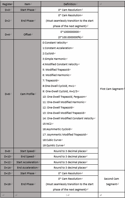
|
Example |
|||||||||||
|
|||||||||||
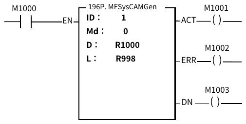
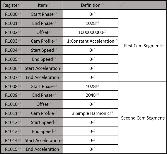
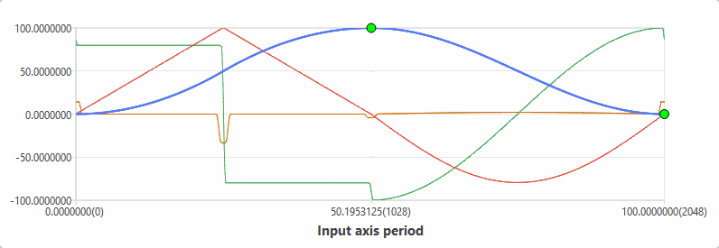

7-22-21 Axis Movement (MFAxMov)
|
FUN197 D P MFAxMov |
Axis Movement |
FUN197 D P MFAxMov |
||||||||||||||||||||||||||||||||||||||||||||||||||||||||||||||||||||||||||||||||||||||||||||||||||||||||||||||||||||||||||||||||||||||||||||||||||||||||||||||||||||||||||||||||||||
|
Symbol |
||||||||||||||||||||||||||||||||||||||||||||||||||||||||||||||||||||||||||||||||||||||||||||||||||||||||||||||||||||||||||||||||||||||||||||||||||||||||||||||||||||||||||||||||||||||
|
|
S: EtherCAT control axis MD: Operating mode PS: Target position V: Speed A: Acceleration D: Deceleration SA: S acceleration curve % SD: S deceleration curve% DR: Direction BF: Speed continuous mode |
|||||||||||||||||||||||||||||||||||||||||||||||||||||||||||||||||||||||||||||||||||||||||||||||||||||||||||||||||||||||||||||||||||||||||||||||||||||||||||||||||||||||||||||||||||||
|
Relay and Register
|
||||||||||||||||||||||||||||||||||||||||||||||||||||||||||||||||||||||||||||||||||||||||||||||||||||||||||||||||||||||||||||||||||||||||||||||||||||||||||||||||||||||||||||||||||||||
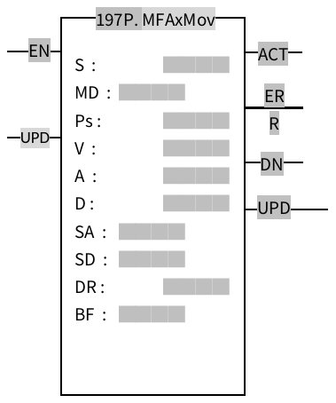
|
FUN197 D P MFAxMov |
Axis Movement |
FUN197 D P MFAxMov |
|
Description |
||
S EtherCAT control axis: EtherCAT_ axis number 1~16 MD operation mode: 0 absolute, 1 relative PS target position: positive and negative numbers, including the [decimal point position] of the [motion axis setting] in the [motion control] ([Axis unit] set mm, [Decimal point position] set 0.001, PS: DR0 = 1000 is equal to 1.000mm) V speed: positive number (a real number greater than zero), including the [decimal point position] of the [motion axis setting] in the [motion control] A Acceleration: positive number (a real number greater than zero), including the [decimal point position] of the [motion axis setting] in the [motion control] D Deceleration: positive number (a real number greater than zero), including the [decimal point position] of the [motion axis setting] in the [motion control] SA S acceleration curve %: positive integer, 0~1000 ‰ SD S deceleration curve %: positive integer, 0~1000 ‰ DR direction: 1 positive direction, 2 negative direction BF: Speed continuous mode: 0 executes the current command immediately, 1 waits for the end of the previous command, 2 selects the lower speed continuous, 3 selects the previous command speed continuous, 4 selects the current command speed continuous, 5 selects the higher speed continuous
When the execution control [EN] is triggered by the lower differential, Fun197 stops the axis position control and resets all output indications.
|
||
|
Example |
|||||||
|
|||||||
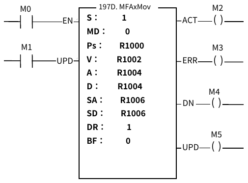
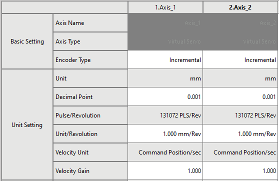
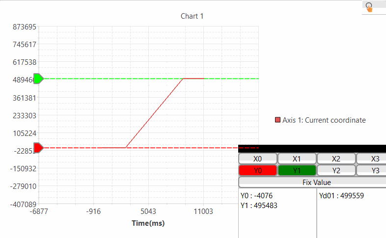
|
The cursor range is set to the interrupt constant feed distance in PS(register R1008). |
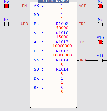 Interrupt Constant Feed
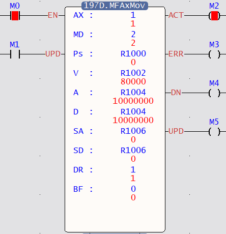
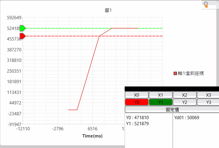
7-22-22 Mapping Table Setting (MFMapTbPrm)
|
FUN198 P MFMapTbPrm |
Mapping Table Setting (MFMapTbPrm) |
FUN198 P MFMapTbPrm |
|||||||||||||||||||||||||||||||||||||||||||||||||||||||||||||||||||||||||||
|
Symbol |
|||||||||||||||||||||||||||||||||||||||||||||||||||||||||||||||||||||||||||||
|
|
Gp: Mapping table group number N: Mapping start table number L: Mapping continuous length |
||||||||||||||||||||||||||||||||||||||||||||||||||||||||||||||||||||||||||||
|
|||||||||||||||||||||||||||||||||||||||||||||||||||||||||||||||||||||||||||||
|
Description |
|||||||||||||||||||||||||||||||||||||||||||||||||||||||||||||||||||||||||||||
Gp mapping table group number: group number 1~16, 0 means all groups. N Mapping table start table number: mapping table number 1~1024, 0 means the entire mapping table L Map Consecutive Length: Number of Consecutive Map Items
When the execution control [EN] is triggered by the lower differential, all output indications are reset.
|
|||||||||||||||||||||||||||||||||||||||||||||||||||||||||||||||||||||||||||||
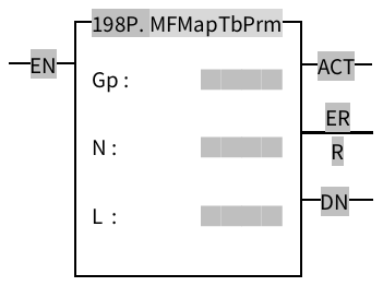
|
FUN198 P MFMapTbPrm |
Mapping Table Setting (MFMapTbPrm) |
FUN198 P MFMapTbPrm |
||||
|
Example |
||||||
Mapping Table
Motion Axis Setting Table
|
||||||

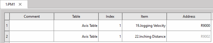
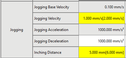
7-22-23 Real Axis to Virtual Axis (MFSysSetVirt)
|
FUN235 P MFSysSetVirt |
Real Axis to Virtual Axis |
FUN235 P MFSysSetVirt |
|||||||||||||||||||||||||||||||||||||||||||||
|
Symbol |
|||||||||||||||||||||||||||||||||||||||||||||||
|
Ladder
|
Operand AX: Axis number to be converted EN: Trigger command ACT: Acting ERR: Conversion error DN: Execution complete |
||||||||||||||||||||||||||||||||||||||||||||||
|
Relay and Register
|
|||||||||||||||||||||||||||||||||||||||||||||||
|
Description |
|||||||||||||||||||||||||||||||||||||||||||||||
|
|||||||||||||||||||||||||||||||||||||||||||||||
|
Example |
|||||||||||||||||||||||||||||||||||||||||||||||
|
Ladder
|
|||||||||||||||||||||||||||||||||||||||||||||||
|
|||||||||||||||||||||||||||||||||||||||||||||||


7-22-24 EtherCAT SDO Read (MFSDOR)
|
Fun236 P MFSDOR |
EtherCAT SDO Read |
Fun236 P MFSDOR |
|||||||||||||||||||||||||||||||||||||||||||||||||||||||||||||||||||||||||||||||||||||||||||||||||||||||||||||||||
|
Symbol |
|||||||||||||||||||||||||||||||||||||||||||||||||||||||||||||||||||||||||||||||||||||||||||||||||||||||||||||||||||
|
Ladder Symbol
|
Operands S : Slave Number I : Index SI : Sub-index LN : Length EC : Register for error code D : Data Register (DWORD) |
||||||||||||||||||||||||||||||||||||||||||||||||||||||||||||||||||||||||||||||||||||||||||||||||||||||||||||||||||
|
|||||||||||||||||||||||||||||||||||||||||||||||||||||||||||||||||||||||||||||||||||||||||||||||||||||||||||||||||||
|
Description |
|||||||||||||||||||||||||||||||||||||||||||||||||||||||||||||||||||||||||||||||||||||||||||||||||||||||||||||||||||
S : Slave Number in EtherCAT I : Index of parameter in slave memory SI : Sub-index of parameter in slave memory LN : Length of the parameter EC : Register for error code D : Data Register (DWORD)
|
|||||||||||||||||||||||||||||||||||||||||||||||||||||||||||||||||||||||||||||||||||||||||||||||||||||||||||||||||||
|
Fun236 P MFSDOR |
EtherCAT SDO Read |
Fun236 P MFSDOR |
|||||||||||||||||||||||||||||||||||||||||||||||||||||||||||||||||||||||||||||||||||||||||||||||||||||||||||||||||
|
Example |
|||||||||||||||||||||||||||||||||||||||||||||||||||||||||||||||||||||||||||||||||||||||||||||||||||||||||||||||||||
|
Ladder
|
|||||||||||||||||||||||||||||||||||||||||||||||||||||||||||||||||||||||||||||||||||||||||||||||||||||||||||||||||||
|
|||||||||||||||||||||||||||||||||||||||||||||||||||||||||||||||||||||||||||||||||||||||||||||||||||||||||||||||||||
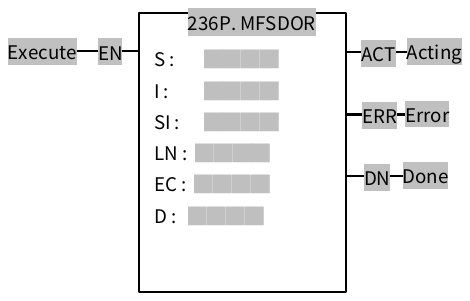
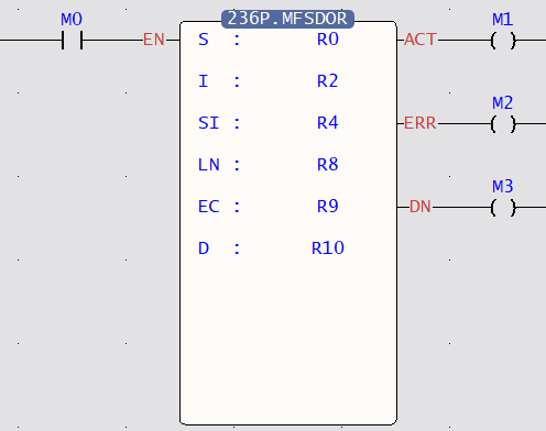
7-22-25 EtherCAT SDO Write (MFSDOW)
|
Fun237 P MFSDOW |
EtherCAT SDO Write |
Fun237 P MFSDOW |
||||||||||||||||||||||||||||||||||||||||||||||||||||||||||||||||||||||||||||||||||||||||||||||||||||||||||||||||
|
Symbol |
||||||||||||||||||||||||||||||||||||||||||||||||||||||||||||||||||||||||||||||||||||||||||||||||||||||||||||||||||
|
Ladder Symbol
|
Operands S : Slave Number I : Index SI : Sub-index LN : Length EC : Register for error code D : Data Register (DWORD) |
|||||||||||||||||||||||||||||||||||||||||||||||||||||||||||||||||||||||||||||||||||||||||||||||||||||||||||||||||
|
||||||||||||||||||||||||||||||||||||||||||||||||||||||||||||||||||||||||||||||||||||||||||||||||||||||||||||||||||
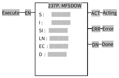
|
Fun237 P MFSDOW |
EtherCAT SDO Write |
Fun237 P MFSDOW |
|
Description |
||
S : Slave Number in EtherCAT I : Index of parameter in slave memory SI : Sub-index of parameter in slave memory LN : Length of the parameter EC : Register for error code D : Data Register (DWORD)
|
||
|
Fun237 P MFSDOW |
EtherCAT SDO Write |
Fun237 P MFSDOW |
|
Example |
||
|
||
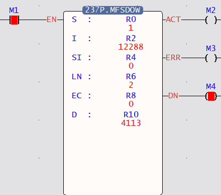
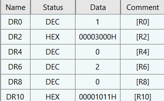
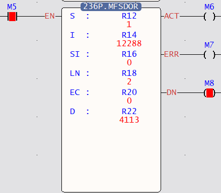

7-22-26 Linear Interpolation (MFAxLMov)
|
Fun238 D P MFAxLMov |
Linear Interpolation |
Fun238 D P MFAxLMov |
||||||||||||||||||||||||||||||||||||||||||||||||||||||||||||||||||||||||||||||||||||||||||||||||||||||||||||||||||||||||
|
Symbol |
||||||||||||||||||||||||||||||||||||||||||||||||||||||||||||||||||||||||||||||||||||||||||||||||||||||||||||||||||||||||||
|
Ladder Symbol
|
Operands TAX : Total Axis Number MD : Operation Mode DR : Direction BF : Continuous Mode D : Parameter Register Start Address EC : Register for Error code |
|||||||||||||||||||||||||||||||||||||||||||||||||||||||||||||||||||||||||||||||||||||||||||||||||||||||||||||||||||||||||
|
Relay and Register
|
||||||||||||||||||||||||||||||||||||||||||||||||||||||||||||||||||||||||||||||||||||||||||||||||||||||||||||||||||||||||||
|
Description |
||||||||||||||||||||||||||||||||||||||||||||||||||||||||||||||||||||||||||||||||||||||||||||||||||||||||||||||||||||||||||
TAX (Total Axis Number) : Axes number in movement – 1 ~ 4 MD (Operation Mode) : 0 – Absolute Positioning, 1 – Relative Positioning. DR (Direction) : 1 – Positive, 2 – Negative. BF (Continuous Mode) : 0: Stop Current Movement 1: Wait Current Mov Finish 2: Continue with Lower Speed 3: Continue with Current Speed 4: Continue with New Speed 5: Continue with higher Speed D : First Register Address of Data. EC : Register for Error Code.
When execution control (EN) is triggered in lower edge, the Fun238 will be stopped, and all the coils will be reset.
|
||||||||||||||||||||||||||||||||||||||||||||||||||||||||||||||||||||||||||||||||||||||||||||||||||||||||||||||||||||||||||
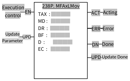
|
Motion data in parameter D:
|
|||||||||||||||||||||||||||||||||||||||||||||||||||||||||||
|
Example |
|||||||||||||||||||||||||||||||||||||||||||||||||||||||||||
|
Ladder
|
|||||||||||||||||||||||||||||||||||||||||||||||||||||||||||
|
|||||||||||||||||||||||||||||||||||||||||||||||||||||||||||

|
Fun238 D P MFAxLMov |
Linear Interpolation |
Fun238 D P MFAxLMov |
||||||||||||||||||||||||||||||||||||||||||
|
Example |
||||||||||||||||||||||||||||||||||||||||||||
|
||||||||||||||||||||||||||||||||||||||||||||
7-22-27 Arc Interpolation (MFAxCirMov)
|
Fun239D P MFAxCirMov |
Arc Interpolation |
Fun239 D P MFAxCirMov |
||||||||||||||||||||||||||||||||||||||||||||||||||||||||||||||||||||||||||||||||||||||||||||||||||||||||||||||||||||||||
|
Symbol |
||||||||||||||||||||||||||||||||||||||||||||||||||||||||||||||||||||||||||||||||||||||||||||||||||||||||||||||||||||||||||
|
Ladder Symbol
|
Operands TAX : Total Axis Number MD : Operation Mode DR : Direction BF : Continuous Mode D : Parameter Register Start Address EC : Register for Error code |
|||||||||||||||||||||||||||||||||||||||||||||||||||||||||||||||||||||||||||||||||||||||||||||||||||||||||||||||||||||||||
|
Relay and Register
|
||||||||||||||||||||||||||||||||||||||||||||||||||||||||||||||||||||||||||||||||||||||||||||||||||||||||||||||||||||||||||

|
Fun239D P MFAxCirMov |
Arc Interpolation |
Fun239 D P MFAxCirMov |
|
Descriotion |
||
TAX (Total Axis Number) : Axes number in movement – 2 ~ 3 MD (Operation Mode) : 0 – Absolute Positioning, 1 – Relative Positioning. DR (Direction) : 1 – Positive, 2 – Negative. BF (Continuous Mode) : 0: Stop Current Movement 1: Wait Current Mov Finish 2: Continue with Lower Speed 3: Continue with Current Speed 4: Continue with New Speed 5: Continue with higher Speed D : First Register Address of Data. EC : Register for Error Code.
When execution control (EN) is triggered in lower edge, the Fun239 will be stopped, and all the coils will be reset.
|
||
|
Fun239D P MFAxCirMov |
Arc Interpolation |
Fun239 D P MFAxCirMov |
||||||||||||||||||||||||||||||||||||||||||||||||||||||||||||||||
|
Motion data in parameter D:
|
||||||||||||||||||||||||||||||||||||||||||||||||||||||||||||||||||
|
Fun239D P MFAxCirMov |
Arc Interpolation |
Fun239 D P MFAxCirMov |
|||||||||||||||||||||||||||||||||||||||||||||||||
|
Example |
|||||||||||||||||||||||||||||||||||||||||||||||||||
|
Ladder
|
|||||||||||||||||||||||||||||||||||||||||||||||||||
|
|||||||||||||||||||||||||||||||||||||||||||||||||||

|
Fun239D P MFAxCirMov |
Arc Interpolation |
Fun239 D P MFAxCirMov |
|
||
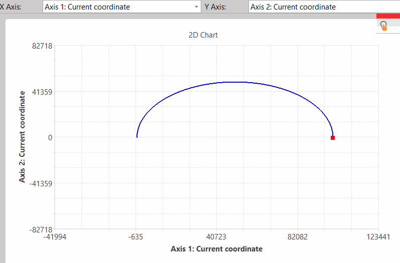
|
Fun239D P MFAxCirMov |
Arc Interpolation |
Fun239 D P MFAxCirMov |
||||||||||||||||||||||||||||||||||||||||||
|
Combining the use of Fun238 and Fun239
|
||||||||||||||||||||||||||||||||||||||||||||
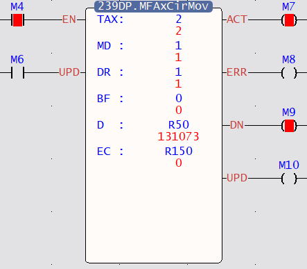
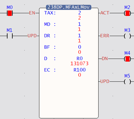
|
Fun239D P MFAxCirMov |
Arc Interpolation |
Fun239 D P MFAxCirMov |
||||||||||||||||||||||||||||||||||||||||||||||||
|
||||||||||||||||||||||||||||||||||||||||||||||||||

7-22-28 Path Movement (MFPathMov)
|
Fun240 D P MFPathMov |
Path Movement( in development ) |
Fun240 D P MFPathMov |
||||||||||||||||||||||||||||||||||||||||||||||||||||||||||||||||||||||||||||||||||||||||||||||||||||||||||||||||||||||||||||||||||||||||||||||||||||||||||||||||||||||||||||||||||||
|
Symbol |
||||||||||||||||||||||||||||||||||||||||||||||||||||||||||||||||||||||||||||||||||||||||||||||||||||||||||||||||||||||||||||||||||||||||||||||||||||||||||||||||||||||||||||||||||||||
|
Ladder Symbol
|
Operands AX1 : Axis 1 Number AX2 : Axis 2 Number AX3 : Axis 3 Number PT : Path Number V : Velocity TA : Acceleration Time TD : Deceleration Time SA : Acceleration S Curve Percentage SD : Deceleration S Curve Percentage EC : Register for Error Code |
|||||||||||||||||||||||||||||||||||||||||||||||||||||||||||||||||||||||||||||||||||||||||||||||||||||||||||||||||||||||||||||||||||||||||||||||||||||||||||||||||||||||||||||||||||||
|
Relay and Register
|
||||||||||||||||||||||||||||||||||||||||||||||||||||||||||||||||||||||||||||||||||||||||||||||||||||||||||||||||||||||||||||||||||||||||||||||||||||||||||||||||||||||||||||||||||||||
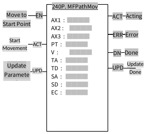
|
Fun240 D P MFPathMov |
Path Movement( in development ) |
Fun240 D P MFPathMov |
|
Description |
||
AX1: EtherCAT axis number range 1~16 AX2: EtherCAT axis number range 1~16 AX3: EtherCAT axis number range 1~16r PT: Path Number range 1~10 V: Velocity is positive integer and include the decimal point in the axis table of the main axis (AX1). TA: Acceleration time of the interpolation. The unit is milli-second. TD: Deceleration time of the interpolation. The unit is milli-second. SA: The percentage of the S curve in acceleration. The range is 0~1000‰. SD: The percentage of the S curve in acceleration. The range is 0~1000‰. EC: Register for Error Code.
When execution control (EN) is triggered in lower edge, the Fun240 will be stopped, and all the coils will be reset.
When start movement (ACT) is triggered in lower edge, the Fun240 will be halt. And the function will be resumed when ACT is back to high level.
|
||
|
Fun240 D P MFPathMov |
Path Movement( in development ) |
Fun240 D P MFPathMov |
|
|
Example |
Requires HMI( in development ) |
||
|
Ladder
|
|||
|
|||
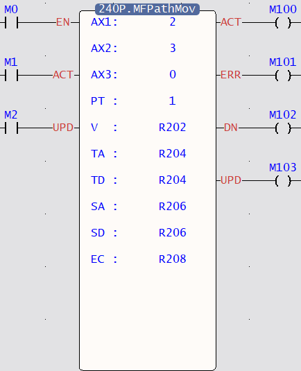
7-23 Other Instructions (FUN115, FUN258)
7-23-1 Data Buffering (DBUF)
|
FUN115P DBUF |
Data Buffering |
FUN115P DBUF |
||||||||||||||||||||||||||||||||||||||||||||||
|
Symbol |
||||||||||||||||||||||||||||||||||||||||||||||||
|
|
ID: Expansion module ID CH: The channel designated for expansion module (0~3) D: Starting position where the data will be saved. |
|||||||||||||||||||||||||||||||||||||||||||||||
|
||||||||||||||||||||||||||||||||||||||||||||||||
|
Description |
||||||||||||||||||||||||||||||||||||||||||||||||
|
It is used to obtain the data buffered on the module, which is suitable for expansion modules that have analog input and support data buffering function. The buffered data collected through this command will not be limited by the program scan cycle, but will be collected based on the sampling cycle set by the module. |
||||||||||||||||||||||||||||||||||||||||||||||||
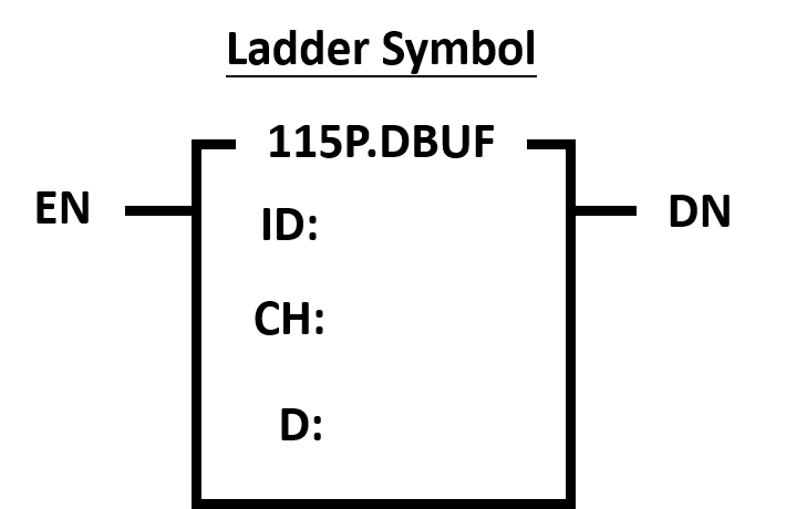
|
FUN115P DBUF |
Data Buffering |
FUN115P DBUF |
||||||
|
Example |
||||||||
|
The data buffer function can be controlled through the relay, and the digital operation value can be stored in the data buffer area to observe the change of the digital operation value. Use methods and instructions Each buffer point updates the digital operation value to the data buffer area according to the processing time of the A/D conversion mode. Each channel can store up to 600 points/ch. Example: When the cache points are set to 600 and the pre-trigger data points are set to 50:
Fig. 137: Example diagram of the data buffering function Setting and preset value
Table 65: Setting of data buffering function |
||||||||

|
FUN115P DBUF |
Data Buffering |
FUN115P DBUF |
||||||||||||
|
The following table shows how to use the data buffer function: Run-time Relay Control
Table 66: Steps to use the data buffering function After the data buffering is completed, use Fun115 DBUF to read the buffered data stored in the module to the address of the PLC designated register. |
||||||||||||||
7-23-2 Tare Weight Deduction Command
|
FUN258P MODCONF |
Tare Weight Deduction Command |
FUN258P MODCONF |
||||||||||||||||||||||||||||||||||||||||||||||||||||||||||||||||||||||||||||||||||||||||||||||||
|
Symbol |
||||||||||||||||||||||||||||||||||||||||||||||||||||||||||||||||||||||||||||||||||||||||||||||||||
|
|
OP: TARESUB ID: Expansion module ID number (0~N) CH: The channel position to be deducted (0~N) SB: The 32BIT value of the tare weight to be deducted |
|||||||||||||||||||||||||||||||||||||||||||||||||||||||||||||||||||||||||||||||||||||||||||||||||
|
||||||||||||||||||||||||||||||||||||||||||||||||||||||||||||||||||||||||||||||||||||||||||||||||||
|
FUN258P MODCONF |
Tare Weight Deduction Command |
FUN258P MODCONF |
|
Description |
||
|
||
7-23-3 Tare Weight Offset Command
|
FUN258P MODCONF |
Tare Weight Offset Command |
FUN258P MODCONF |
||||||||||||||||||||||||||||||||||||||||||||||||||||||||||||||||||||||||||||||||||||||||||||||||
|
Symbol |
||||||||||||||||||||||||||||||||||||||||||||||||||||||||||||||||||||||||||||||||||||||||||||||||||
|
|
OP: TAREZROFFSET ID: Expansion module ID number (0~N) CH: The channel position to be deducted (0~N) WR: Starting register for offset command setting |
|||||||||||||||||||||||||||||||||||||||||||||||||||||||||||||||||||||||||||||||||||||||||||||||||
|
||||||||||||||||||||||||||||||||||||||||||||||||||||||||||||||||||||||||||||||||||||||||||||||||||
|
Description |
||||||||||||||||||||||||||||||||||||||||||||||||||||||||||||||||||||||||||||||||||||||||||||||||||
|
WR list:
|
||||||||||||||||||||||||||||||||||||||||||||||||||||||||||||||||||||||||||||||||||||||||||||||||||
|
FUN258P MODCONF |
Tare Weight Offset Command |
FUN258P MODCONF |
|
Description |
||
*The tare weight offset command is only supported by the LCR module, not by the LC. |
||


7-24 Floating Point Instructions (FUN200~220)
7-24-1 CONVERSION OF INTEGER TO FLOATING POINT NUMBER
|
FUN200D P I🡪F |
CONVERSION OF INTEGER TO FLOATING POINT NUMBER |
FUN200D P I🡪F |
||||||||||||||||||||||||||||||||
|
Symbol |
※Because floating-point numbers occupy two registers, when using indirect addressing, it should be noted that odd-numbered registers cannot be used. |
|||||||||||||||||||||||||||||||||
|
|
S: Starting register of Integer to be converted D: Starting register to store the result of conversion The register used by the operand must be an even address. For example, R8 is legal, but R7 is not. S and D operands can be combined with V, Z, P0~P9 indicators for indirect addressing applications |
|||||||||||||||||||||||||||||||||
|
||||||||||||||||||||||||||||||||||
|
Description |
||||||||||||||||||||||||||||||||||
|
||||||||||||||||||||||||||||||||||
|
FUN200D P I🡪F |
CONVERSION OF INTEGER TO FLOATING POINT NUMBER |
FUN200D P I🡪F |
||||
|
Example |
||||||
|
||||||


7-24-2 CONVERSION OF FLOATING POINT NUMBER TO INTEGER
|
FUN201D P F🡪I |
CONVERSION OF FLOATING POINT NUMBER TO INTEGER |
FUN201D P F🡪I |
||||||||||||||||||||||||||||
|
Symbol |
※Because floating-point numbers occupy two registers, when using indirect addressing, it should be noted that odd-numbered registers cannot be used. |
|||||||||||||||||||||||||||||
|
|
S: Starting register of Integer to be converted D: Starting register to store the result of conversion The register used by the operand must be an even address. For example, R8 is legal, but R7 is not. S and D operands can be combined with V, Z, P0~P9 indicators for indirect addressing applications |
|||||||||||||||||||||||||||||
|
||||||||||||||||||||||||||||||
|
Description |
||||||||||||||||||||||||||||||
|
||||||||||||||||||||||||||||||
|
FUN201D P F🡪I |
CONVERSION OF FLOATING POINT NUMBER TO INTEGER |
FUN201D P F🡪I |
||||
|
Example |
||||||
|
||||||
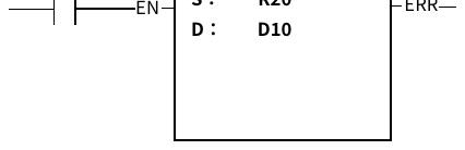

7-24-3 FLOATING POINT NUMBER ADDITION
|
FUN202 P FADD |
FLOATING POINT NUMBER ADDITION |
FUN202 P FADD |
|||||||||||||||||||||||||||||||||||||||||
|
Symbol |
※Because floating-point numbers occupy two registers, when using indirect addressing, it should be noted that odd-numbered registers cannot be used. |
||||||||||||||||||||||||||||||||||||||||||
|
|
Sa: Augend Sb: Addend D: Destination register to store the results of the addition The register used by the operand must be an even address. For example, R8 is legal, but R7 is not. Sa, Sb, D may combine with V, Z, P0~P9 to serve indirect addressing |
||||||||||||||||||||||||||||||||||||||||||
|
|||||||||||||||||||||||||||||||||||||||||||
|
Description |
|||||||||||||||||||||||||||||||||||||||||||
|
|||||||||||||||||||||||||||||||||||||||||||
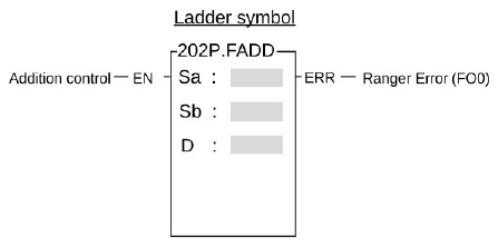
|
FUN202 P FADD |
FLOATING POINT NUMBER ADDITION |
FUN202 P FADD |
||||
|
Example |
||||||
|
||||||
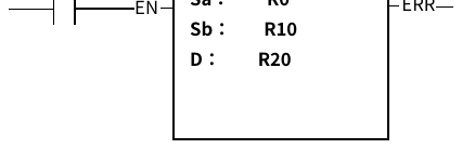
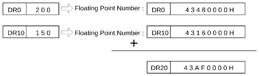
7-24-4 FLOATING POINT NUMBER SUBTRACTION
|
FUN203 P FSUB |
FLOATING POINT NUMBER SUBTRACTION |
FUN203 P FSUB |
|||||||||||||||||||||||||||||||||||||||||
|
Symbol |
※Because floating-point numbers occupy two registers, when using indirect addressing, it should be noted that odd-numbered registers cannot be used. |
||||||||||||||||||||||||||||||||||||||||||
|
|
Sa: Minuend Sb: Subtrahend D: Destination register to store the results of the subtraction The register used by the operand must be an even address. For example, R8 is legal, but R7 is not. Sa, Sb, D may combine with V, Z, P0~P9 to serve indirect addressing. |
||||||||||||||||||||||||||||||||||||||||||
|
|||||||||||||||||||||||||||||||||||||||||||
|
Description |
|||||||||||||||||||||||||||||||||||||||||||
|
|||||||||||||||||||||||||||||||||||||||||||
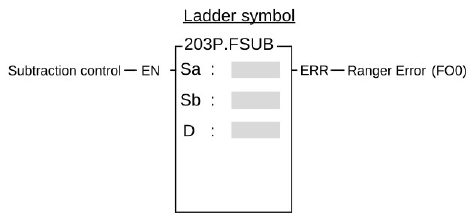
|
FUN203 P FSUB |
FLOATING POINT NUMBER SUBTRACTION |
FUN203 P FSUB |
||||
|
Example |
||||||
|
||||||
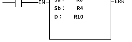

7-24-5 FLOATING POINT NUMBER MULTIPLICATION
|
FUN204 P FMUL |
FLOATING POINT NUMBER MULTIPLICATION |
FUN204 P FMUL |
||||||||||||||||||||||||||||||||||||||||
|
Symbol |
※Because floating-point numbers occupy two registers, when using indirect addressing, it should be noted that odd-numbered registers cannot be used. |
|||||||||||||||||||||||||||||||||||||||||
|
|
Sa: Multiplicand Sb: Multiplier D: Destination register to store the results of the multiplication The register used by the operand must be an even address. For example, R8 is legal, but R7 is not. Sa, Sb, D may combine with V, Z, P0~P9 to serve indirect addressing |
|||||||||||||||||||||||||||||||||||||||||
|
||||||||||||||||||||||||||||||||||||||||||
|
Description |
||||||||||||||||||||||||||||||||||||||||||
|
||||||||||||||||||||||||||||||||||||||||||

|
FUN204 P FMUL |
FLOATING POINT NUMBER MULTIPLICATION |
FUN204 P FMUL |
||||
|
Example |
||||||
When M10= Performs the multiplication of the data specified at Sa and Sb :
|
||||||
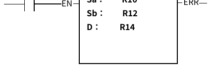
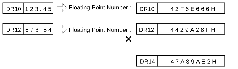
7-24-6 FLOATING POINT NUMBER DIVISION
|
FUN205 P FDIV |
FLOATING POINT NUMBER DIVISION |
FUN205 P FDIV |
||||||||||||||||||||||||||||||||||||||||
|
Symbol |
※Because floating-point numbers occupy two registers, when using indirect addressing, it should be noted that odd-numbered registers cannot be used. |
|||||||||||||||||||||||||||||||||||||||||
|
|
Sa: Dividend Sb: Divisor D: Destination register to store the results of the division The register used by the operand must be an even address. For example, R8 is legal, but R7 is not. Sa, Sb, D may combine with V, Z, P0~P9 to serve indirect addressing |
|||||||||||||||||||||||||||||||||||||||||
|
||||||||||||||||||||||||||||||||||||||||||
|
Description |
||||||||||||||||||||||||||||||||||||||||||
|
||||||||||||||||||||||||||||||||||||||||||
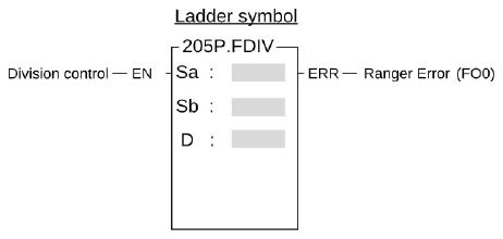
|
FUN205 P FDIV |
FLOATING POINT NUMBER DIVIDION |
FUN205 P FDIV |
||||
|
Example |
||||||
|
||||||
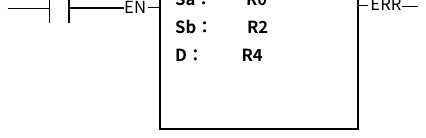

7-24-7 FLOATING POINT NUMBER COMPARE
|
FUN206 P FCMP |
FLOATING POINT NUMBER COMPARE |
FUN206 P FCMP |
||||||||||||||||||||||||||||||||
|
Symbol |
※Because floating-point numbers occupy two registers, when using indirect addressing, it should be noted that odd-numbered registers cannot be used. |
|||||||||||||||||||||||||||||||||
|
|
Sa: The register to be compared Sb: The register to be compared The register used by the operand must be an even address. For example, R8 is legal, but R7 is not. Sa, Sb may combine with V, Z, P0~P9 to serve indirect addressing. |
|||||||||||||||||||||||||||||||||
|
||||||||||||||||||||||||||||||||||
|
Description |
||||||||||||||||||||||||||||||||||
|
||||||||||||||||||||||||||||||||||
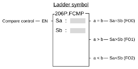
|
FUN206 P FCMP |
FLOATING POINT NUMBER COMPARE |
FUN206 P FCMP |
|||||
|
Example |
|||||||
|
|||||||

7-24-8 FLOATING POINT NUMBER ZONE COMPARE
|
FUN207 P FZCP |
FLOATING POINT NUMBER ZONE COMPARE |
FUN207 P FZCP |
||||||||||||||||||||||||||||||||||||||||
|
Symbol |
※Because floating-point numbers occupy two registers, when using indirect addressing, it should be noted that odd-numbered registers cannot be used. |
|||||||||||||||||||||||||||||||||||||||||
|
|
S: Register for zone comparison SU: The upper limit value SL: The lower limit value The register used by the operand must be an even address. For example, R8 is legal, but R7 is not. S, SU, SL may combine with V, Z, P0~P9 to serve indirect address application |
|||||||||||||||||||||||||||||||||||||||||
|
||||||||||||||||||||||||||||||||||||||||||
|
Description |
||||||||||||||||||||||||||||||||||||||||||
|
||||||||||||||||||||||||||||||||||||||||||

|
FUN207 P FZCP |
FLOATING POINT NUMBER ZONE COMPARE |
FUN207 P FZCP |
||||
|
Example |
||||||
X0= 🡪 FLOATING ZONE COMPARE 🡪 Y0 = 1 Results of execution |
||||||
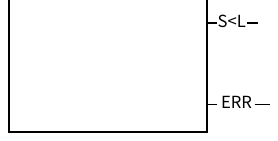
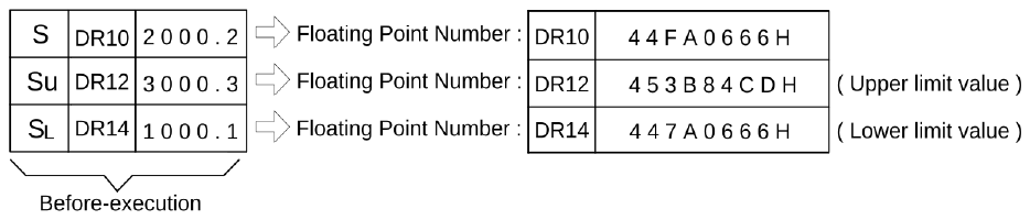
7-24-9 FLOATING POINT NUMBER SQUARE ROOT
|
FUN208 P FSQR |
FLOATING POINT NUMBER SQUARE ROOT |
FUN208 P FSQR |
||||||||||||||||||||||||||||||||
|
Symbol |
※Because floating-point numbers occupy two registers, when using indirect addressing, it should be noted that odd-numbered registers cannot be used. |
|||||||||||||||||||||||||||||||||
|
|
S: Source register to be taken square root D: Register for storing result (Square root value) The register used by the operand must be an even address. For example, R8 is legal, but R7 is not. S, D may combine with V, Z, P0~P9 to serve indirect address application |
|||||||||||||||||||||||||||||||||
|
||||||||||||||||||||||||||||||||||
|
Description |
||||||||||||||||||||||||||||||||||
|
||||||||||||||||||||||||||||||||||
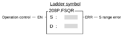
|
FUN208 P FSQR |
FLOATING POINT NUMBER SQUARE ROOT |
FUN208 P FSQR |
||||
|
Example |
||||||
When X0= ,take the square root of S :
|
||||||
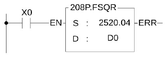
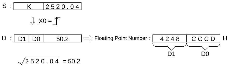
7-24-10 SIN TRIGONOMETRIC INSTRUCTION
|
FUN209 P FSIN |
SIN TRIGONOMETRIC INSTRUCTION |
FUN209 P FSIN |
||||||||||||||||||||||||||||||||
|
Symbol |
※Because floating-point numbers occupy two registers, when using indirect addressing, it should be noted that odd-numbered registers cannot be used. |
|||||||||||||||||||||||||||||||||
|
|
S: Source register to be taken SIN D: Register for storing result (SIN value) The register used by the operand must be an even address. For example, R8 is legal, but R7 is not. S, D may combine with V, Z, P0~P9 to serve indirect address application. |
|||||||||||||||||||||||||||||||||
|
||||||||||||||||||||||||||||||||||
|
Description |
||||||||||||||||||||||||||||||||||
|
||||||||||||||||||||||||||||||||||
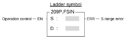
|
FUN209 P FSIN |
SIN TRIGONOMETRIC INSTRUCTION |
FUN209 P FSIN |
||||
|
Example |
||||||
|
||||||
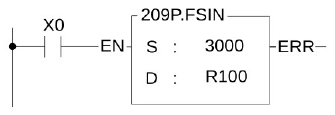
 in DR100.

7-24-11 COS TRIGONOMETRIC INSTRUCTION
|
FUN210 P FCOS |
COS TRIGONOMETRIC INSTRUCTION |
FUN210 P FCOS |
||||||||||||||||||||||||||||||||
|
Symbol |
※Because floating-point numbers occupy two registers, when using indirect addressing, it should be noted that odd-numbered registers cannot be used. |
|||||||||||||||||||||||||||||||||
|
|
S: Source register to be taken COS D: Register for storing result (COS value) The register used by the operand must be an even address. For example, R8 is legal, but R7 is not. S, D may combine with V, Z, P0~P9 to serve indirect address application |
|||||||||||||||||||||||||||||||||
|
||||||||||||||||||||||||||||||||||
|
Description |
||||||||||||||||||||||||||||||||||
|
||||||||||||||||||||||||||||||||||
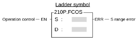
|
FUN210 P FCOS |
COS TRIGONOMETRIC INSTRUCTION |
FUN210 P FCOS |
||||
|
Example |
||||||
|
||||||

 in DR200.
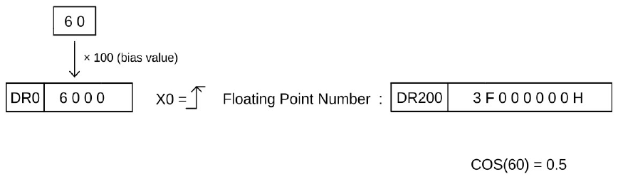
7-24-12 TAN TRIGONOMETRIC INSTRUCTION
|
FUN211 P FTAN |
TAN TRIGONOMETRIC INSTRUCTION |
FUN211 P FTAN |
||||||||||||||||||||||||||||||||
|
Symbol |
※Because floating-point numbers occupy two registers, when using indirect addressing, it should be noted that odd-numbered registers cannot be used. |
|||||||||||||||||||||||||||||||||
|
|
S: Source register to be taken TAN D: Register for storing result (TAN value) The register used by the operand must be an even address. For example, R8 is legal, but R7 is not. S, D may combine with V, Z, P0~P9 to serve indirect address application |
|||||||||||||||||||||||||||||||||
|
||||||||||||||||||||||||||||||||||
|
Description |
||||||||||||||||||||||||||||||||||
|
||||||||||||||||||||||||||||||||||
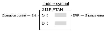
|
FUN211 P FTAN |
TAN TRIGONOMETRIC INSTRUCTION |
FUN211 P FTAN |
||||
|
Example |
||||||
|
||||||
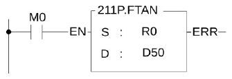

7-24-13 CHANGE SIGN OF THE FLOATING POINT NUMBER
|
FUN212 P FNEG |
CHANGE SIGN OF THE FLOATING POINT NUMBER |
FUN212 P FNEG |
|||||||||||||||||||||
|
Symbol |
※Because floating-point numbers occupy two registers, when using indirect addressing, it should be noted that odd-numbered registers cannot be used. |
||||||||||||||||||||||
|
|
D: Register to be changed sign The register used by the operand must be an even address. For example, R8 is legal, but R7 is not. D may combine with V, Z, P0~P9 to serve indirect address application |
||||||||||||||||||||||
|
|||||||||||||||||||||||
|
Description |
|||||||||||||||||||||||
|
|||||||||||||||||||||||
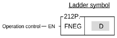
|
FUN212 P FNEG |
CHANGE SIGN OF THE FLOATING POINT NUMBER |
FUN212 P FNEG |
||||
|
Example |
||||||
The instruction at left negates the value of the DR0 register, and stores it back to DR0.
|
||||||
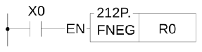
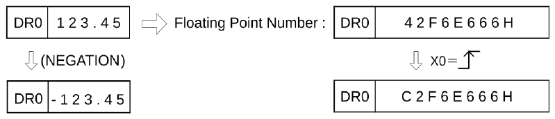
7-24-14 FLOATING POINT NUMBER ABSOLUTE VALUE
|
FUN213 P FABS |
FLOATING POINT NUMBER ABSOLUTE VALUE |
FUN213 P FABS |
|||||||||||||||||||||
|
Symbol |
※Because floating-point numbers occupy two registers, when using indirect addressing, it should be noted that odd-numbered registers cannot be used. |
||||||||||||||||||||||
|
|
D: Register to be taken absolute value The register used by the operand must be an even address. For example, R8 is legal, but R7 is not. D may combine with V, Z, P0~P9 to serve indirect address application |
||||||||||||||||||||||
|
|||||||||||||||||||||||
|
Description |
|||||||||||||||||||||||
|
|||||||||||||||||||||||
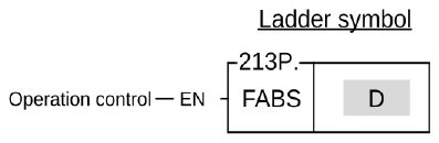
|
FUN213 P FABS |
FLOATING POINT NUMBER ABSOLUTE VALUE |
FUN213 P FABS |
||||
|
Example |
||||||
|
||||||

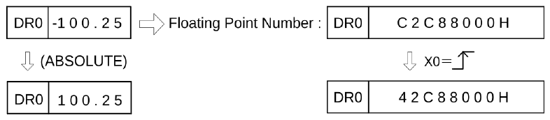
7-24-15 FLOATING POINT ARC SINE FUNCTION
|
FUN218 P FASIN |
FLOATING POINT ARC SINE FUNCTION |
FUN218 P FASIN |
||||||||||||||||||||||||||||||||||||||||
|
Symbol |
※Because floating-point numbers occupy two registers, when using indirect addressing, it should be noted that odd-numbered registers cannot be used. |
|||||||||||||||||||||||||||||||||||||||||
|
|
S: Source data or register to be calculated the arc sine value. The register used by the operand must be an even address. For example, R8 is legal, but R7 is not. D: Register for storing the result. S, D may combine with V, Z, P0~P9 to serve indirect address application. MD: In order to make the user more intuitive in use, MD can choose the output mode: MD is 0: the output value is the radius, and the output is a floating point number (32bit). MD is 1: the output value is an angle, and the output is a positive integer (16bit). |
|||||||||||||||||||||||||||||||||||||||||
|
||||||||||||||||||||||||||||||||||||||||||
|
Description |
||||||||||||||||||||||||||||||||||||||||||
|
||||||||||||||||||||||||||||||||||||||||||
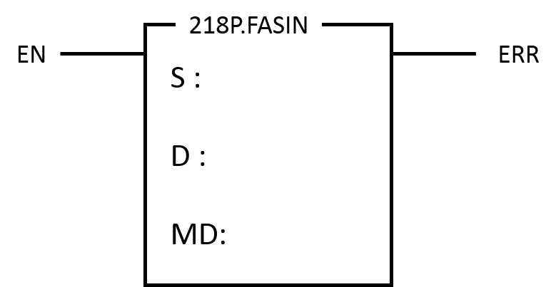
|
FUN218 P FASIN |
FLOATING POINT ARC SINE FUNCTION, sin-1 |
FUN218 P FASIN |
||||
|
Example |
||||||
|
||||||

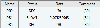
7-24-16 FLOATING POINT ARC COSINE FUNCTION
|
FUN219 P FACOS |
FLOATING POINT ARC COSINE FUNCTION |
FUN219 P FACOS |
|||||||||||||||||||||||||||||||||||||||||
|
Symbol |
※Because floating-point numbers occupy two temporary registers, when using indirect addressing, it should be noted that odd-numbered temporary registers cannot be used. |
||||||||||||||||||||||||||||||||||||||||||
|
|
S: Source data or register to be calculated the arc cosine value. The register used by the operand must be an even address. For example, R8 is legal, but R7 is not. D: Register for storing the result. S, D may combine with V, Z, P0~P9 to serve indirect address application. MD: In order to make the user more intuitive in use, MD can choose the output mode: MD is 0: the output value is the radius, and the output is a floating point number (32bit). MD is 1: the output value is an angle, and the output is a positive integer (16bit). |
||||||||||||||||||||||||||||||||||||||||||
|
|||||||||||||||||||||||||||||||||||||||||||
|
Description |
|||||||||||||||||||||||||||||||||||||||||||
|
|||||||||||||||||||||||||||||||||||||||||||
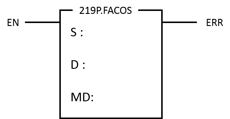
|
FUN219 P FACOS |
FLOATING POINT ARC COSINE FUNCTION |
FUN219 P FACOS |
||||
|
Example |
||||||
|
||||||
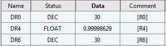
Tip: press ← → to switch chapters, Ctrl+K to search