Click on the setting option in【System】and the related setting window will be displayed at the work space of the window.
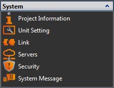
Figure 42 System
3.1 Project Information
3.1.1 Project File
Information on the project files including the name of the project, creator, and the last save time.
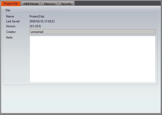
Figure 43 Project File
3.1.2 HMI Model
Detailed information on the HMI can be seen here, including the series, name, screen information and other information.
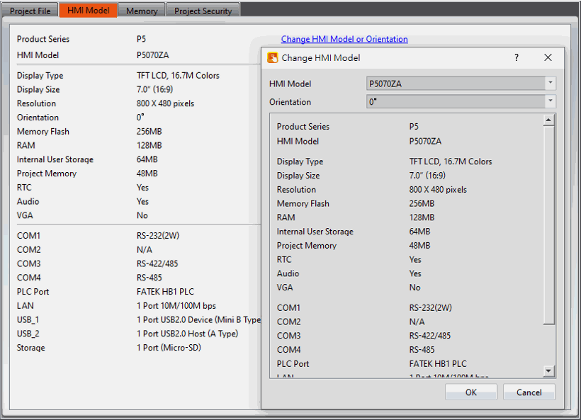
Figure 44 HMI Model
3.1.3 Memory
The information of the memory configuration, users can set the size of the register and the type of backup memory used in the project. (For more details , please refer to chapter23.1-Internal Address Register Range)
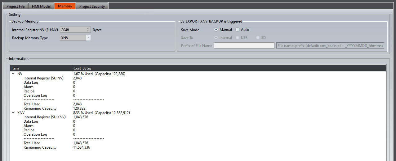
Figure 45 Memory
【SS_EXPORT_XNV_BACKUPis triggered】
When this System Tags is on, it will save XNV, XNVA and other Preservation Memory Registers UPS memory as files.
If user choose【Manual】, it will pop up a window to let users choose the project to open and check asks for the path and file name to be saved.
If user choose【Auto】, It will follow the settings of【Save To】and【File name prefix】generate files at the destination.
If you want to import the exported file into another HMI, you need to use【SS_IMPORT_XNV_BACKUP】in【System Tags】or【Import XNV Backup】in【Function Switch】. Human machine interface will restart after the import is successful.
3.1.4 Project Security
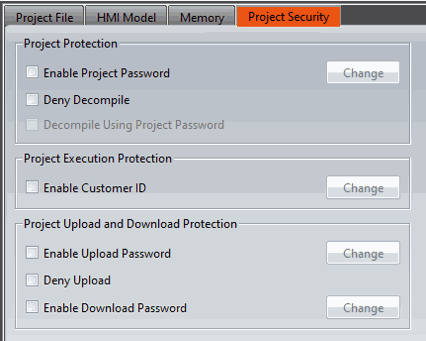
Figure 46 Project Security
Table 14 Project Security
|
Item |
Description |
|||||||||
|
【Project Protection】 |
【Enable Project Password】 After checking, the next time you open this project, you need to enter a password to open it. You can set the password of the project in the【Change】at the back. If this item is set, after the project is uploaded from HMI and decompiled, a password is required to open the project. 【Deny Decompile】 When checked, decompilation will be prohibited for this project. After uploading from the HMI, if you want to decompile, there will be a prompt message that you are not allowed. 【Decompile Use Project Password】 This option needs to be checked【Enter project password】to select. After checking, when the project is to be decompiled, it will be required to enter the password of【Project Protection】. |
|||||||||
|
【Project Execution Protection】 |
When the project is executed, it will compare whether the password set here is the same as the password of the【Customer ID】in the【System Settings】of the HMI. The following are the rules for judging whether to enter the project.
【Enable Customer ID】 After checking, you can set the password of the customer ID code in【Change】at the back. For setting the customer identification code on the HMI, please refer to section 24.2.10.2-【Security】 【Security】 |
|||||||||
|
【Project Upload and Download Protection】 |
【Enable Upload Password】 After downloading to the HMI, you will need to enter the password the next time you want to upload it; if you make the project into a USB flash drive to update the file, and then update it to the HMI, you will need to enter the upload password when using the software to upload at this time. 【Deny Upload】 After enabling, the project will not be able to upload from the HMI to the computer. 【Enable Download Password】 If you choose to use the【Download】function in【Tools (T)】, you will need to enter the download password when you want to download to the HMI protected by the download password. ※If you use【Download Current Project】in【Project (P)】, you will not be asked to enter the download password. |
3.2 Unit Setting
3.2.1 Basic
The basic setting includes the Startup, Idle State, and Object.
It is recommended to enable【Screen Saver】and【Backlight Saver】functions and set them within 60 minutes to avoid image afterimages caused by the HMI displaying the same screen for a long time.
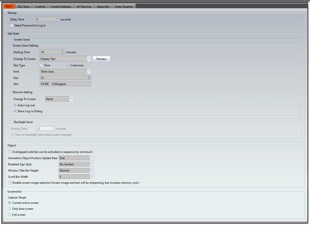
Figure 47 Unit Setting-Basic
Table 15 Unit Setting-Basic
|
Item |
Description |
||||
|
【Startup】 |
The startup delay time can be set up to 255 seconds, and the project will not enter until the end of the countdown. 【Need Password to Log In】 Power on the HMI before enter the project, you need to enter a valid password in【Security】to log in. Notice to the following points when using this function:
|
||||
|
【Idle State】 |
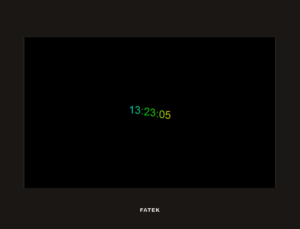
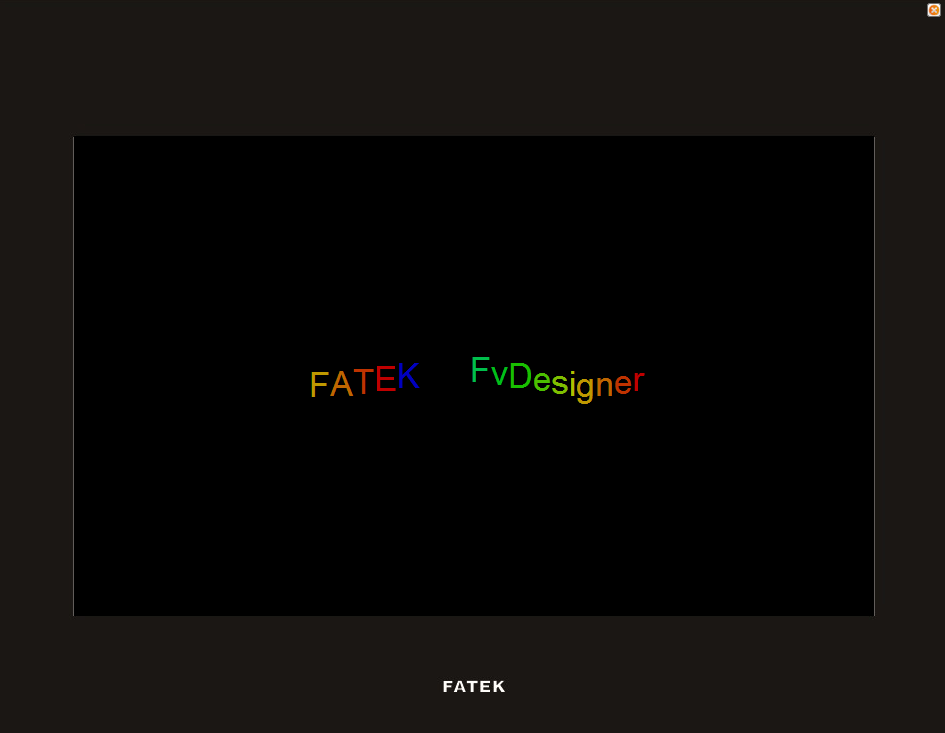
In the idle state, the screen saver and backlight saver can be set. When the operation is idle for a period of time, the screen saver can be switched to the preset window or the backlight saver can be turned on to achieve the power saving effect. 【Screen Saver】 In addition to switching to the user-defined basic screen, the screen saver also provides a default screen saver screen, which has two modes of displaying【Time】and【Custom Text】, which is convenient for users to use without configuring any screen .
【Font】 Set the screen saver time or customize text font. 【Size】 Set the screen saver time or customize text size. 【Text】 Set the screen saver time or customize text. |
||||
|
【Resume Settings】 |
Settings for actions the HMI takes when exiting the Idle State are set here. 【Change to Screen】 Allows the user to control which screen the HMI is at upon exiting from the screen saver.【None】means stay in the screen which was before entering the screen saver. For example, if choose【None】, if it is idle for more than the waiting time set by the screen saver, then enter the screen saver. When the screen saver is restored, the HMI will display on screen 5. 【Auto Log-out】 When the【Security】function is used and the login level is greater than 0 before entering the screen saver, the HMI will log out the password to level 0 when this option is checked and the screen saver is restored. 【Show Log-in Dialog】 When the【Security】function is used and the login level is greater than 0 before entering the screen saver, the HMI will automatically display the login dialog when this option is checked and the screen saver is restored. This option is valid only if the【Auto Log-out】option is checked. |
||||
|
【Backlight Saver】 |
Check whether to enable the backlight energy saving function. 【Waiting Time】 Set the waiting time of no operation to turn off the HMI backlight. 【Turn on backlight when base screen changed】 If checked, when the screen enters the backlight energy saving mode, if the HMI has a page change action (such as using an alarm or change screen by register), the screen will be forced to light up. |
||||
|
【Object】 |
【Overlapped switches can be activated in sequence by one touch】If there are multiple buttons overlapped in the same position, when this position is touched, the overlapped buttons will be triggered at the same time. If 4 buttons (M0, M1, M2, M3) were overlapped, then they will be triggered. 【Animation Object Position Update Rate】 Update rate for the object. 【Disabled Sign Style】 There are 4 styles to satisfy the different requirements and the setting will be applied in the whole project.
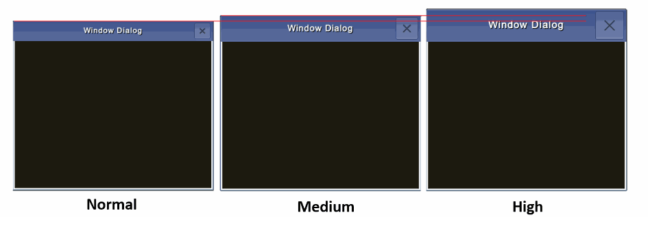
【Window Title Bar Height】 After enabling this function, you can adjust the height of the title bar above the pop-up window, pop-up keyboard, etc. It should be noted that it will not have an effect when the model is PC and when using simulation.
【Scroll Bar Width】 This is to set the scroll width of all objects with sliders in the project, such as【Alarm Display】. If the scroll width of this component is set by device, the settings here will be read. 【Disable screen image optimize(Screen image and text will be sharpening】 Will optimize the image and words, but the use of memory will increase. |
||||
|
【Screenshot】 |
【Current Active Screen】Captures the topmost window, which may be a popup window or a keyboard. 【Base Screen Only】Captures only the bottom-most base screen of the current display and does not include any pop-up windows above it. 【Full Screen】Captures everything currently displayed on the screen, exactly as seen. |

3.2.2 PLC Sync
Writing to or reading time from PLC.
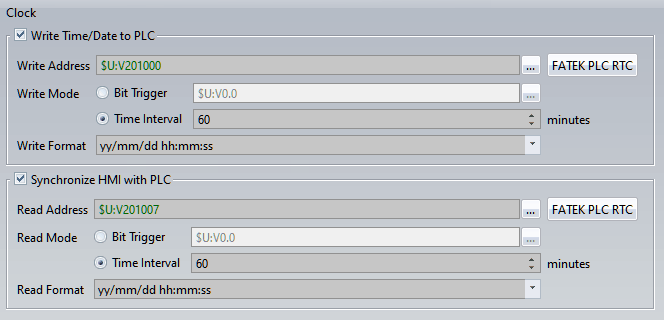
Figure 48 Unit Setting-PLC Sync
Table 16 Unit Setting-PLC Sync
|
Item |
Description |
|||||||||||||||||||||
|
【Clock】 |
HMI has built-in RTC clock. It can be synchronized with PLC RTC by this function. 【Write Time/Date to PLC】 【Write Address】Write the value in Time Register of HMI to the Write Address of PLC. 【Write Mode】Set the execution conditions 【Bit Trigger】when the bit set on, it will sync PLC. Please note that this bit will not be automatically reset. 【Time Interval】Set how long it takes to execute, the range is 1~255 minutes. 【Write Format】Set the format for writing data. 【Synchronize HMI with PLC】 【Read Address】read the value in set address and write to the Time Register of HMI 【Read Mode】Set the execution conditions 【Bit Trigger】when the bit set on, it will sync PLC. Please note that this bit will not be automatically reset. 【Time Interval】Set how long it takes to execute, the range is 1~255 minutes. 【Read Format】Set the format for reading data. Write Address and Read Address data format, 7 consecutive WORDs will be processed every time:
Note: The value of Sunday is 0. |
3.2.3 Custom
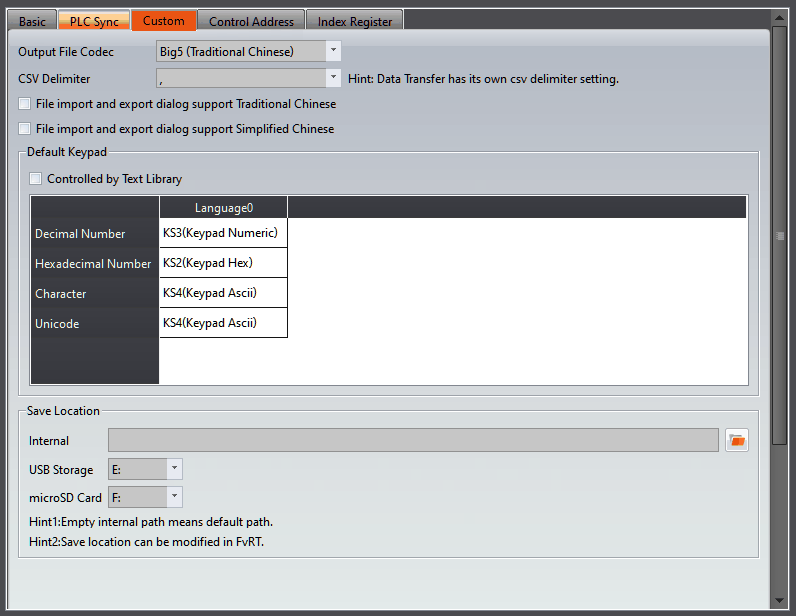
Figure 49 Unit Setting-Custom
Table 17 Unit Setting-Custom
|
Item |
Description |
|
【Output File Codec】 |
When the developer has set the export data(Data Log, Alarm, etc.) to the HMI, micro SD Card, or the USB storage, the data format can be selected. The exported file’s data format [Big5(Traditional Chinese), GB18030(Simplified Chinese), UTF-8 encoding] can be chosen such that it satisfies the user’s computer environment. For example, as the Traditional Chinese Windows environment, open a new project by default as Big5(Traditional Chinese). |
|
【CSV Delimiter】 |
When the developer has set the export data(Data Log, Alarm, etc.) to the HMI, micro SD Card, or the USB storage, they can choose the CSV file format using either a comma ",", semicolon ";", or “tab” as the delimiter. |
|
【File import and export dialog support Traditional Chinese/Simplified Chinese】 |
When this option is selected, the system will support Chinese keyboard input for manually entering the file name during runtime. |
|
【Default Keypad】 |
The developer can configure the preset keypad for the operating interface so that this pre-set keypad will pop up when operating text or numeric input objects. Available settings include Decimal Number, Hexadecimal Number, Character and Unicode. 【Controlled by Text Library】 When the customer has a customized keypad and would like to switch to another keypad when switch to another text library, this function should be checked to enable. |
|
【Save Location】 |
When FvDesigner model choose as PC, will appear【Save Location】setting option, figure as shown below, this option is mainly to set the default location where FvRT is stored 【Internal】 Set when the FvRT is excuted, if setting export the file to【Internal】in the unit setting, the file will be save to the specified location, if this field is empty, then will save to the default location. Is use the default location to store, the system will create a folder the name is same as the project name under the same path. For example: The project save in: C:\Files\Project11.fpj then the system defaults to the【Internal】storage location: C:\Files\Project11\run\storage\ internal. 【USB Storage】 Set when the FvRT is excuted, if setting export the file to【USB Storage】in the unit setting, the file will be save to the specified location. 【microSD Card】 Set when the FvRT is excuted, if setting export the file to【microSD Card】in the unit setting, the file will be save to the specified location. |
3.2.4 Control Address
The following control addresses are read from PLC periodically, and set or trigger specific internal functions.
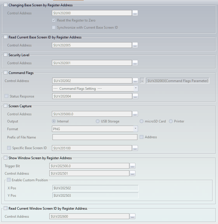
Figure 50 Unit Setting-Control Address
Table 18 Unit Setting-Control Address
|
Item |
Description |
|||||||||||||||
|
【Changing Base Screen by Register Address】 |
【Control Address】 HMI changes the current screen to target screen, according to the value of register address, the address can be set from HMI internal register and PLC address. For example: set $U:V202000 to 3, then the screen will change to BS3. 【Reset the Register to Zero】 The value can be reset to 0 after changing screens. 【Synchronize with the Current Base Screen ID】 The value of the register will sane as the ID of the basic screen. *note: reset to 0 and synchronize features can not use at the same time. |
|||||||||||||||
|
【Read Current Base Screen ID by Register Address】 |
The current screen displayed on the HMI will have its screen ID written to the specified register. For example, if the HMI screen is base screen 3, the value of the specified register will be 3. The screen ID of the current screen can also be read by accessing the value inside the OP_BASE_SCREEN_ID register. |
|||||||||||||||
|
【Security Level】 |
The【security】level can be modified by the value of register address. |
|||||||||||||||
|
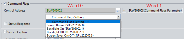
【Command Flags】 |
【Control Address】includes 2 addresses.
【Status Response】 Return Word 0 trigger status to this address. |
|||||||||||||||
|
【Screen Capture】 |
The screenshot file name will be generated based on the date and time, for example : 250102_120526.png 【Control Address】You can assign a Bit address to trigger the screenshot. 【Output】Choose the output destination. 【Format】Select the output file format. 【Prefix of File Name】If you set a prefix such as "AAA", the resulting filename will be AAA_250102_120526.png. If left blank, no prefix will be added. 【Specific Base Screen ID】When checked, writing a value to the address before triggering will capture a screenshot of the specified screen. |
|||||||||||||||
|
【Show Window Screen by Register Address】 |
【Trigger Bit】 This address controls whether to popup window screen. 【Control Address】 This address controls the window screen ID, For example: $U:V202501=2, then display window screen 2 (WS2) 【Enable Custom Position】 After enabling, you can set the position of the window screen through the register |
|||||||||||||||
|
【Read Current Window Screen ID by Register Address】 |
【Control Address】 When checked, this address will display the ID of the topmost window screen |
3.2.5 IoT Service
It provides users to set the connection status of FATEK cloud functions on the HMI and GPS positioning messages of the HMI.
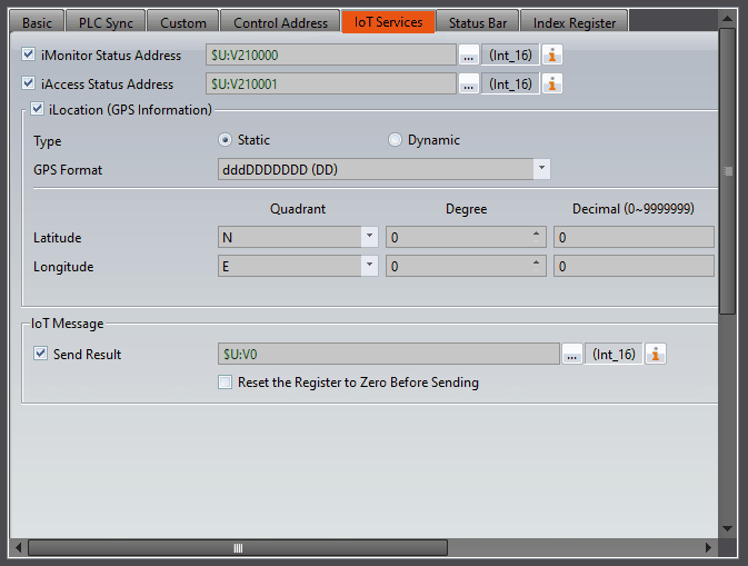
Figure 51 Unit Setting-IoT Service
Table 19 Unit Setting-IoT Service
|
Item |
Description |
||||||||||||||||||||||||||||||||||||||||||||||
|
【iMonitor Status Address】 |
Let user know the current iMonitor connection status through numeric display.
|
||||||||||||||||||||||||||||||||||||||||||||||
|
【iAccess Status Address】 |
Let user know the current iAccess connection status through numeric display.
|
||||||||||||||||||||||||||||||||||||||||||||||
|
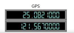
【iLocation (GPS Information)】 |
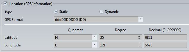
Support static and dynamic two types. GPS format has dddDDDDDDD, dddmmMMMMM, and dddmmssSSS three types. In static mode, users can set the parameter of the latitude and longitude.
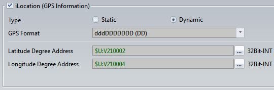
In dynamic mode, users can set the GPS coordinate in the specified address.
When selecting the dynamic range, the range of values that can be entered is North Latitude: N (0~900,000,000), South Latitude: S (0~-900,000,000) East: E (0~1,800,000,000), West longitude: W (0~-1,800,000,000)
Or using script(note: because it is in 32bit-INT, need to use tag)
|
||||||||||||||||||||||||||||||||||||||||||||||
|
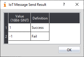
【IoT Message】 |
When using HMI to transmit messages to third -party devices via IoT function, it will display the transmission result here.
|

3.2.6 Status Bar
The status bar can assist the user to quickly confirm the status of the HMI.
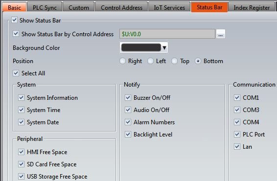
Figure 52 Unit Setting-Status Bar
Table 20 Unit Setting- Status Bar
|
Item |
Description |
||||||||||||||||||
|
【Show Status Bar】 |
Set to display the status bar. When this option is selected, the rest of the options are available to configure. 【Show Status Bar By Control Address】 Set a signal to control the status bar visibility. 【Background Color】 Set the background color of the status bar. 【Position】 Select status bar to position. Positions include: up/down/left/right edges. 【Select all】 Select system, peripheral devices, notification, and communication. |
||||||||||||||||||
|
【System】 |
|
||||||||||||||||||
|
【Peripheral devices】 |
|
||||||||||||||||||
|
【Notify】 |
|
||||||||||||||||||
|
【Communication】 |
|



3.2.7 Index Register
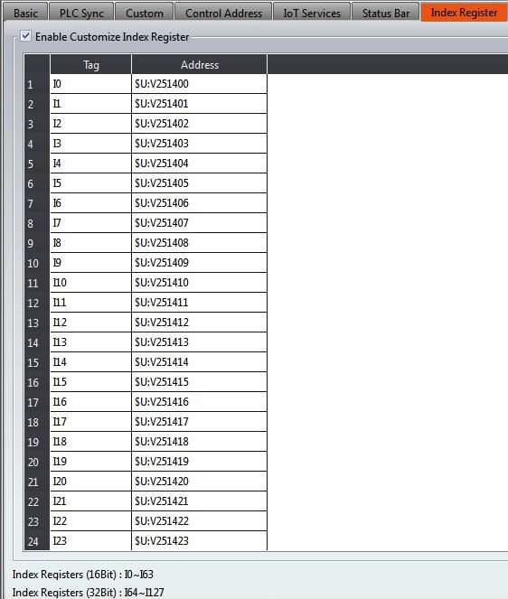
Figure 53 Unit Setting-Index Register
Table 21 Unit Setting- Index Register
|
Item |
Description |
|
【Enable Customize Index Register】 |
Enable index register to use default register or customize, you can define the corresponding address in the address field after enable, it can be HMI internal address or PLC register address, for example, I0 can correspond to PLC R100 address, for designer easy to use, please refer to ch0- Index Register for more details about index register. |
3.3 Link
FATEK HMI can connect to the following types of devices.
Table 22 Device Connection
|
Device |
Description |
|
PLC Device |
Connecting to the various brands of Device/PLC Driver. |
|
Printer |
Connecting to the printer. |
|
Video Input |
Connecting to USB camera. |
|
USB Barcode Scanner |
Connecting to USB Barcode Scanner. |
3.3.1 PLC Device
Setting up the communication device Device/PLC: The connection overview will list the information of all the devices connected to the HMI; use the Add/Edit/Delete functions to configure the connection device.
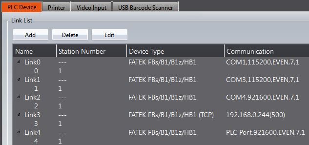
Figure 54 Device Connection Setting–PLC Device
Double click on a device in the list to open the device property setting window directly for editing. The interface of sub-link is as shown below.
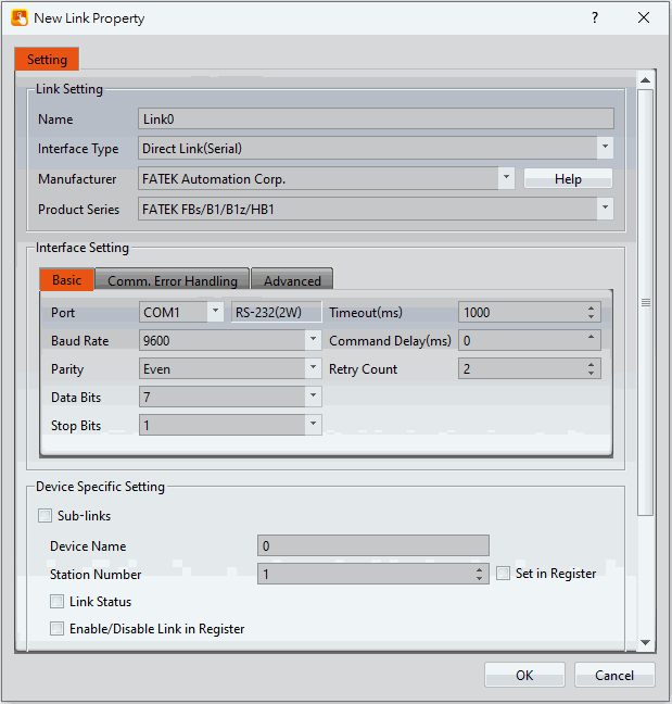
Figure 55 Link Properties
Table 23 Link Property Settings
|
Item |
Description |
||||||||||||||||||||||||||||||||||||
|
【Link Setting】 |
Basic settings for connection.
|
||||||||||||||||||||||||||||||||||||
|
【Interface Setting】 |
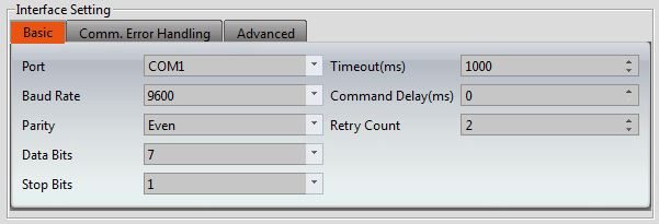
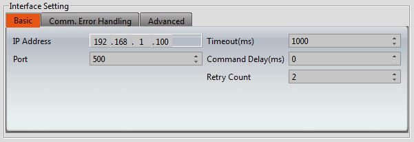
Communication interface setup; the interface will change according to the【Interface Type】in【Link Setting】. When the【Interface Type】is【Direct Link(Serial)】
When【Interface Type】is【Direct Link(Ethernet)】
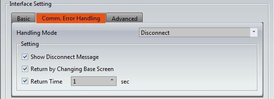
【Comm. Error Handling】 Select an action to handle a communication error.
There are four handling modes as follows:
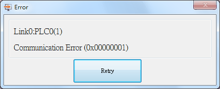
Process each communication data sequentially. If the data cannot be queried this scanning time, system will re-query it again next time. The communication error window shows up when communication has failed. User can close the window and continue to operate the current screen. Show Disconnect Message: Every time a communication error has occurred, an error message window will pop up. Operation may continue once the error message is closed.
When a communication error occurs, the links stop communicating. It resets the condition to re-start communication according to Disconnect Setting. 【Disconnect Setting】 Show Disconnect Message: The communication error window shows up when communication has failed. User can close the window and continue to operate the current screen. Return by Changing Base Screen: The disconnected link restarts communication after changing the base screen. Return Time: The disconnected link re-starts communication when return time is reached.
The communication error window shows up when communication has failed. User can not close the window and has to stop operating the current screen. When communication is restored, the window closes automatically.
The communication error window shows when communication has failed. User can not close the window and has to stop to operating the current screen. Retry switch is available to attempt to reestablish communication. When the communication is restored, the window closes automatically.
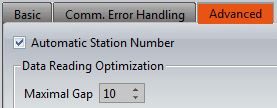
For more info on communication error codes, refer to Chapter 32-Communication Error Codes 【Advanced】
|
||||||||||||||||||||||||||||||||||||
|
【Device Specific Setting】 |
Configuration setting of the equipment.
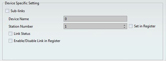
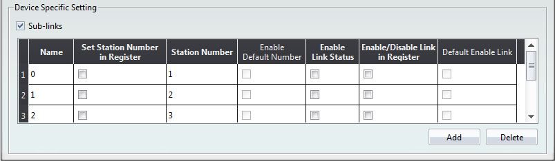
【Sub-links】 When 【Sub-links】 is not selected, the system operates in a 1-to-1 connection mode. When 【Sub-links】 is selected, 1-to-multiple connections are supported.
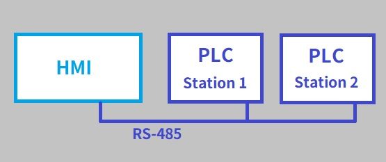
【Sub-links】Architecture Diagram
As shown in the diagram above, the sub-link function allows multiple devices of the same model to be connected using the same communication method. Please note: Set as figure, device name 0 communicate with station no.1 link device, device name 1 , enable【Set Station Number in Register】dynamically decision by $U:V20, for example, $U:V20=5, then it will communicate with station no.5 link device and enable default number as 5, device name 2 communicate with station no.3 link device and enable link status, enable【Link Status】when $U:V40=0 indicates that the connection is normal, when $U:V40=1 indicates that the connection is abnormal. Device name 3 communicate with station no.4, then enable【Enable/Disable Link in Register】, when $U:V51.0 = ON will communicate with this device, when $U:V51.0 = OFF will not communicate with this device |
3.3.1.1 Input Address Configuration Settings
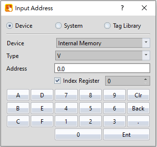
In the 【Input Address】section, you can open the device dropdown menu and select a previously created device from the 【Link】list.
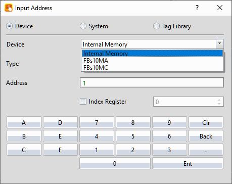
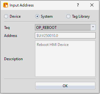
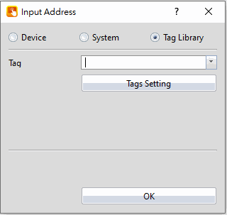
Figure 56 PLC Input Address Setting Dialog
Table 24 Access Address Settings
|
Item |
Description |
||||||||||
|
【Device】 |
Register address inside the HMI/PLC device. After selecting the connection, the address will display the register pattern for the designer to choose from and fill in the address of the pattern. Fill addresses in sequentially and the legal addresses will be displayed in green and illegal ones in red. This ensures correct addresses will always be entered.
|
||||||||||
|
【System】 |
Special register address inside the HMI. The address type displays information on the register function and the corresponding register address of the function.
|
||||||||||
|
【Tag】 |
Use the tags defined in the custom tag library.
|
||||||||||
|
【Use Index Address】 |
Please refer to the section 23.2-Index Register |
3.3.2 Printer
A printer can be connected to the HMI and can print out HMI screen captures or other information. To print, a printer has to be configured through selecting type of printer to connect and the port on the HMI it is connected to. Printing can also be controlled through a control address. See Chapter 19.4.2.4 -【Function Switch】for more details.
The【Printer】settings page is shown below. Each option is explained.
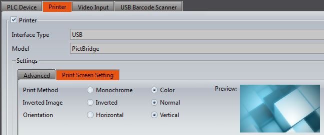
Figure 57【Printer】Settings Screen
Table 25【Printer】Settings
|
Property |
Description |
|
【Printer】 |
Check to enable printer configuration. |
|
【Interface Type】 |
Support USB and serial two types, when the project model is PC , the PC Default Printer can be selected. |
|
【Model】 |
【USB】- PictBridge Use mini-USB to connect to pictbridge printers. The following models are available for reference, but the settings may be slightly different between brands. There is no guarantee that the HMI can support all printer models. http://www.cipa.jp/pictbridge/CertifiedModels/ 【Serial】- Argox PPLB, EPSON ESC/POS, SPRT A Series Argox PPLB- label printer EPSON ESC/POS- Dox matrix/pos printer SPRT A Series- SPRT’s A series printer 【PC Default Printer】 Print through the PC default printer. |
|
【Settings】 |
【Basic】 Set the related port parameter. 【Advanced】 Set the encoding to communicate with the printer (EPSON only needs to be aware of), and print zoom and whether to cut. 【Print Screen Setting】 Set the Print Method, Inverted Image, and Orientation. |
3.3.2.1 Argox PPLB tutorial
By using Argox Company provided software ArgoBar Pro to generate .prn file then import it to FvDesigner, allows FvDesigner and HMI to do tags editing. Currently only support PPLB series tag.
ArgoBar Pro offical download and simple tutorial: https://reurl.cc/D15d0e
- Build project
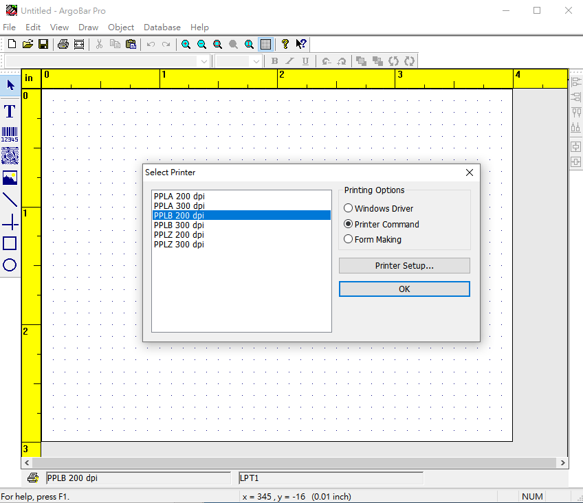
Select PPLB 200dpi, Printing Options select Printer Command, or it may show format error after import tags.
- Set up the tag for replacement
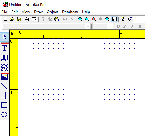
Currently we only support the following three functions:
|
Item |
Description |
|
【Text】 |
Font: Need to select PPLB Font type so when importing the .prn file the FvDesigner will support the label replace function. If the font type is in TrueType, the file will be viewed as an image but not replaceable words. String: The ‘Text String’ field can only text English if text Chinese then the file will be viewed as image and can not be replaced after import to FvDesigner. |
|
【Barcode】 |
Just follow the ArgoBar Pro software attention. |
|
【QR Code】 |
Just follow the ArgoBar Pro software attention. |
- Output file
Click ‘print’ and check the checkbox ‘print to file’ to output the .prn file.
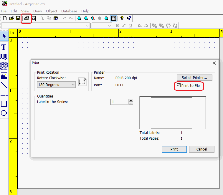
- Import to FvDesigner
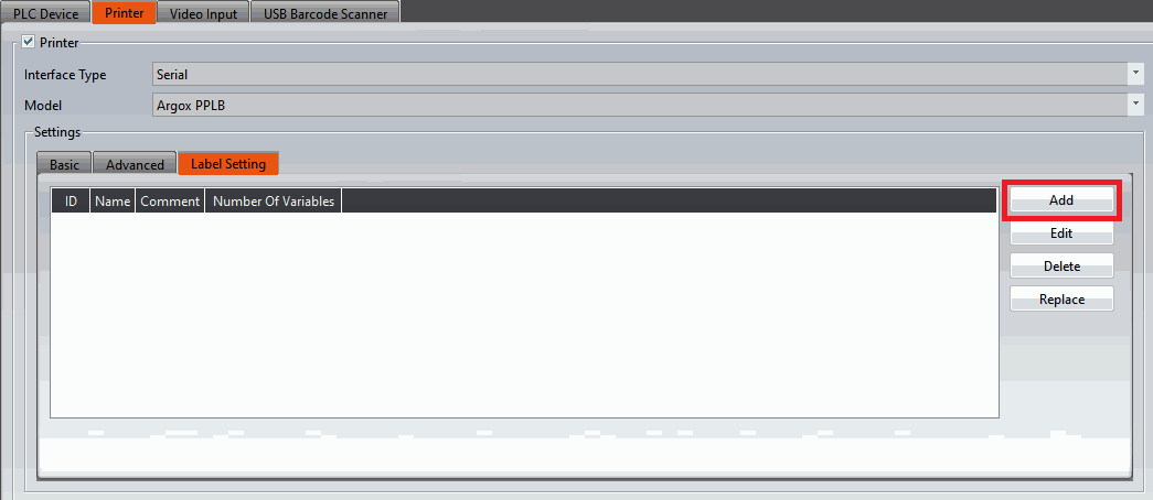
Click add button to import .prn file then the label properties can be set.
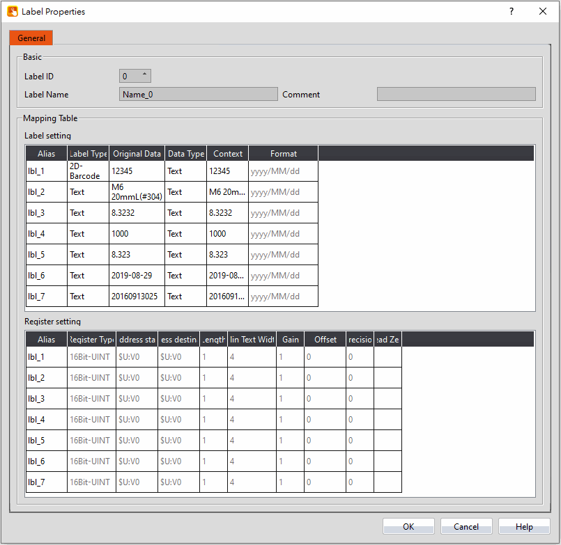
|
Item |
Description |
|
【General】 |
【Label ID】 Set a number to the label for printing. 【Label Name】 Name the label. 【Comment】 Add comment for the label. |
|
【Mapping Table】 |
【Alias】 Name the field. 【Label Type】 Tags set in the ArgoBar Pro. 【Original Data】 Default value to be displayed. 【Data Type】 Text(Static Word), Dataitem(Time), and Register. |
3.3.3 Video Input
3.3.3.1 USB Camera
When the project wants to connect to USB Camera need to set the settings here first so that the video input display can do action, for more detail please refer to ch19.4.35-【Video Input Display】, in addition, when the alarm occurs, photos taken by the camera can also be sent to designated person via email, for more detail please refer to ch8.3-Alarm Application Example, this function only support after OS v1.0.14 or PC version.
If the HMI and the camera disconnected, change to another page and return for retry connection.
Note 1: This function only support in P5 all series HMI.
Note 2: This function only sipport HMI OS version 1.0.14 or later and PC version.
Note 3: This function has been tested it support MJPEG format.
Note 4: Currently has tested successful for supporting the following 3 USB cameras
- Logitech: C270
- Logitech: C922 HD 1080P
- Microsoft: LifeCam HD-3000
The【Video Input】settings page is shown below. Each option is explained.
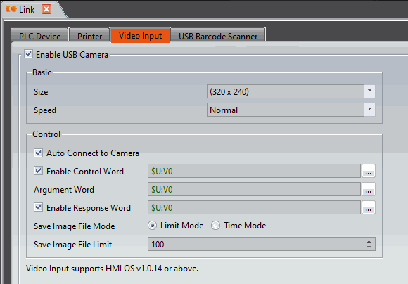
Figure 58【Video Input】Setting Window
Table 26【Video Input】property settings
|
Options |
Description |
|||||||||||||||||||||||||||||||||||||||||||||||||||||||||||||||||||||||||||||||||||||||||||||||||||
|
【Basic】 |
【Enable USB Camera】 Set whether to enable USB camera function. 【Size】 Set the size of the video input display, whether the selected size is available depends on the camera support. 【Speed】 Set the screen update speed, it will take up more HMI system resources if select fast. |
|||||||||||||||||||||||||||||||||||||||||||||||||||||||||||||||||||||||||||||||||||||||||||||||||||
|
【Control】 |
【Auto Connect to Camera】 Set whether to Auto Connect to Camera function. 【Enable Control Word】 Control the video input display through control word, whether the control is available depends on the camera support. 【Argument Word】 When control word is enabled, argument word is the parameter to change the control of camera. When control word or argument word have changed, the setting will be written.
【Enable Response Word】 Display whether the video iuput display was enable success or the result of control word setting.
【Save Image File Mode】
When using the control word to save the file, there is no limit for the numbers of the files, but it can no longer save the file if the storage space is not enough. The file name format would be the current date and time yyMMdd_hhmmss.jpg (For example: 200702_145018.jpg). 【Save Image File Limit】 This option will be displayed under【Limit Mode】, and the range of the saving files is 0~999. |
3.3.3.2 IP Camera
Available after V1.7.20. This feature is supported only on G03 or higher HMI models or when running on FvRT. This section explains how to enable the function. For component details, please refer to
19.4.36 – "Network Camera Player."
- The computer must have DirectX 11 or later installed to use GPU acceleration. (Windows 10 and Windows 11 come with DirectX 12 installed by default. If DirectX is not installed, all image processing will be handled by the CPU, which may result in high CPU usage.)
- The computer must have Microsoft Media Foundation installed.
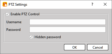
- This feature supports PTZ. PTZ stands for Pan (horizontal rotation), Tilt (vertical rotation), and Zoom. The camera must support the relevant ONVIF certification (Profile S) and be equipped with physical motors (such as a speed dome camera) to allow remote PTZ control and lens direction adjustment. Available PTZ functions may vary depending on the camera model.
- If playback does not work at all, it may indicate that the computer system does not support media playback functionality.

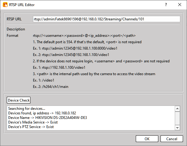
Figure 59【IP Camera】Setting Window
Table 27【IP Camera】property settings
|
Options |
Description |
|
【Name】 |
Item Name, you may enter any name freely. |
|
【RTSP URL】 |
Click the Edit button to open the editing window for input. The RTSP Address Editor provides format guidelines, and after confirmation it will perform a validation check to ensure the device is valid. It can verify whether the RTSP IP address is valid, whether the device is a camera, and whether it supports PTZ.
|
|
【PTZ Control】 |
You can configure whether to enable PTZ control. The user must enter a username and password.
|
|
【Notice】 |
|
3.3.4 USB Barcode Scanner
Scan the barcode and display the information on the numerical input display.
Please note that this function is a mandatory address setting, so after enabling this function, the numeric and text input display cannot use the【USB Barcode Scanner】function.
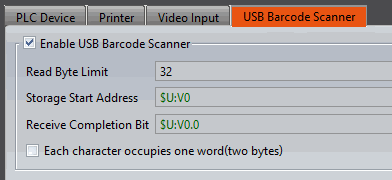
Figure 60【USB Barcode Scanner】Setting Window
Table 28【USB Barcode Scanner】property settings
|
Item |
Description |
|
【Read Byte Limit】 |
Set the maximum data that can be displayed. |
|
【Storage Start Address】 |
Set the storage address. |
|
【Receive Completion Bit】 |
The bit will be true when scanning complete. |
|
【Each character occupies one word(two bytes)】 |
Set whether to enable one character per character. |
3.3.5 RFID Reader
This feature currently only communicates with "HEM-WLC-RFID". Please visit https://www.fatek.com/en/download.php?act=list&cid=28 to view the specifications.
3.3.5.1 Enable RFID Reader
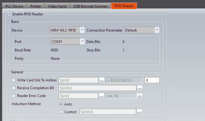
Figure 61【RFID】Setting Window
Table 29【RFID】property settings
|
Item |
Description |
||||||||
|
【Basic】 |
Setting up communication with the RFID device. The connection method for "HEM-WLC-RFID" is RS-485. Parameter is【Baud Rate】: 9600,【Parity】: None,【Data Bits】: 8,【Stop Bits】: 1 |
||||||||
|
【General】 |
【Write Card Uid To Address】The data read from the card will be displayed at the specified address. 【Receive Completion Bit】When the card reader is triggered, this bit will also be triggered, and it will not automatically reset. 【Reader Error Code】If there is an abnormality in the data read by the card reader, an error code will be displayed.
【Induction Method】 【Auto】In automatic mode, the card will be read simply by bringing it close to the card reader. 【Trigger】The card reader will only fetch data when the card is brought close to it and the trigger bit is triggered. |
3.3.5.2 RFID Advance functions
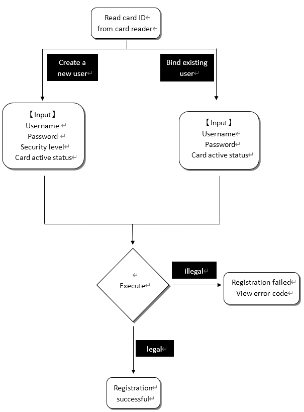
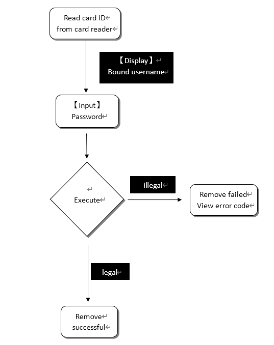
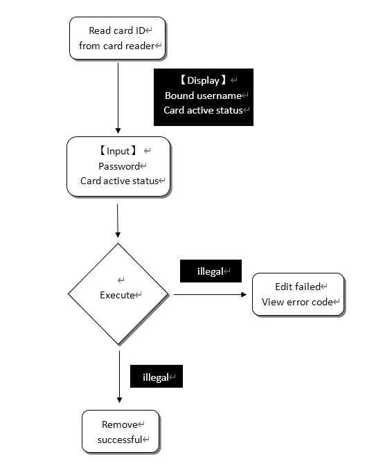
In the advanced functions, users can integrate with the 【Security】 feature. For example, to use the RFID advanced function, the mode in 【Security】must be changed to 【User】. There are a total of 4 operation modes supported in the advanced functions: 【Read Mode】, 【Register Mode】, 【Remove Mode】, and 【Edit Mode】.
【Read Mode】: This is the default mode. When the card reader reads a card number, the status of this card number will be displayed in the 【Read Result】.
【Register Mode】: Binds the card number to a specific username.
【Remove Mode】: Unbinds the card number.
【Edit Mode】: Modifies the active status of the card number.
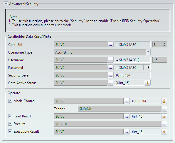
Figure 62 Advanced Setting Screen for【RFID】【Security】
Table 30 Advanced Setting Properties【RFID】【Security】
|
Item |
Description |
||||||||||||||||||||||||||||||||||||||||||||||||||||
|
【Cardholder Data Read/Write】 |
【Card Uid】Specifies the address of the card number to be operated, with a maximum of 16 characters. 【Username Type】Selects the format of the username. 【Username】Sets the username to be operated, which must be the same as the user set in【Security】. 【Password】Sets the password of the user being operated, which must match the【Security】settings for authentication. 【Security Level】Displays the security level of the user bound to the card. 【Card Active Status】Sets the active status of the card, with 0 for disabled and 1 for enabled. |
||||||||||||||||||||||||||||||||||||||||||||||||||||
|
【Operate】 |
【Mode Control】Sets the operation mode. 【Trigger】Switches the operation mode after being triggered.
【Read Result】When the current mode is【Read】, the read result will be displayed here. In Read Mode, the result is displayed whenever a card is scanned, without additional trigger bits.
【Excute】When selecting【Register】,【Remove】,【Edit】, the function is executed by triggering this bit. 【Excution Result】The result of triggering the execution bit will be displayed here.
|
||||||||||||||||||||||||||||||||||||||||||||||||||||
|
【Receive Completion Bit】 |
The bit will be true when scanning complete. |
||||||||||||||||||||||||||||||||||||||||||||||||||||
|
【Each character occupies one word(two bytes)】 |
Set whether to enable one character per character. |
※In addition to using 【Operation】 to modify the mode, you can also use 【Function Switch】 to modify it.
3.3.5.3 Advance functions operation procedure
【Read Mode】
|
|
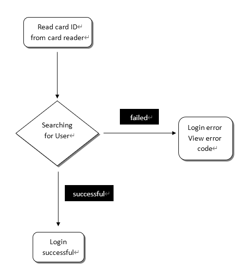
【Register Mode】
|
|
【Remove Mode】
|
|
【Edit Mode】
|
|
Tip: press ← → to switch chapters, Ctrl+K to search