Calculation, and Power Sequence Requirements
FBS-PLC internally has three kinds of circuit: a 5VDC logic circuit, a 24VDC driver circuit (driver output devices, for
example: relay, transistor, and etc), and a 24VDC input circuit. Only the 5VDC logic circuit and 24VDC output circuit
are powered by the built-in power supply for main/expansion units or powered by expansion power supply modules
(FBs-EPW-AC, FBs-EPW-D24), and the 24VDC input circuit can be choose to powered by the external power supply
or the built-in power supply of main/expansion units or 24VDC sensor of FBs-EPW-AC/D12/D24. Expansion modules
other than main/expansion units do not contain any power supply and are powered by the power supply inside the
main/expansion units or expansion power supply (FBS-EPW-AC, FBs-EPW-D24). Main/expansion units or expansion
power supply with their model numbers suffixed with “-D12/-D24” means is operated by DC power source. Otherwise,
AC power source is used.
|
•Caution |
|
In industrial environments, main power may irregularly experience a surge current or high voltage pulse caused by the start or shut down of high power equipment. Users are advised to take necessary measures (for example, the use of isolation transformer or other MOV suppression devices) for the protection of PLC and its peripherals. |
|
5.1Specifications and Wiring of AC Power Sourced Power Supply |
The available AC power supplies of FBS-PLC are the 14 Watt (SPW14-AC) supply for 10/14 PTs main unit, the 24 Watt
(SPW24-AC) supply for 20~60PTs main/expansion unit, and the 14 Watt expansion supply (FBS-EPW-AC) for
expansion modules. Except that the FBS-EPW-AC is an independent module, SPW14-AC and SPW24-AC are to be
installed on a main unit or inside an expansion unit, where their appearances are invisible. The following table lists the
specifications:
Model
Spec SPW14-AC SPW24-AC FBS-EPW-AC
Item
Voltage 100 ~ 240VAC, -15% / +10%
Input Range
Frequency 50 / 60HZ ±5%
Max. Power Consumption 21W / 14W 36W / 24W 21W / 14W
Inrush Current 20A@264VAC
Allowable Power Interrupt <20ms
Fuse Spec. 2A,250V
Isolation Type Transformer/Photocouple Isolation, 1500VAC/minute
5VDC (logic circuit) N/A*2 5V, ±5%, 1A(max) 5V, ±5%, 0.4A(max)
24VDC 24V±10%, 200mA(max)*3 24V, ±10%, 400mA(max) 24V, ±1%, 250mA(max)
(output circuit)
24VDC (input circuit) 24V,±10%, 400mA(max) 24V, ±10%, 400mA(max) 24V, ±10%, 250mA(max)
Note * 1:The 5VDC (for logic circuit) output power and the 24VDC (for output circuit) power can be accessed from the “I/O expansion
output header” located on the right side of the main/expansion units for expansion modules. And the 5VDC power is also
used by communication board (CBxx) or communication module (CMxx). The 24VDC power for input circuits is provided
from the farthest 2 upper left terminals (labeled “+24V OUT-”) on the input terminal block of main/expansion unit to input
circuit in expansion module or other sensors.


Note * 2:The 5VDC power of 10/14PTs main unit is generated from the 24VDC power in the output circuit, with specifications of 5VDC±10% and 400mA (max) (Circuit is located on the I/O board of 10/14PTs main unit).
Note * 3:Without any I/O expansion interface, the 24VDC power in 10/14PTs main unit is for its output circuit alone and cannot be used for other purposes.
•Caution
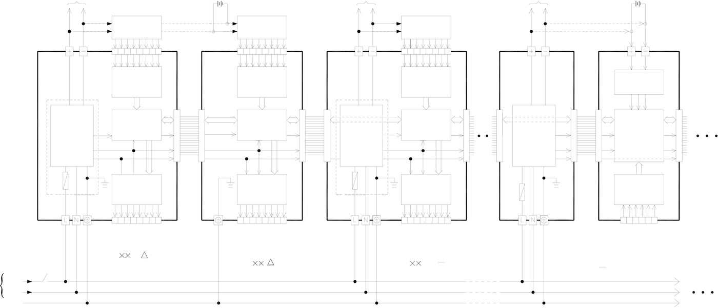
The schematic diagram of AC power supply wiring in main/expansion units is shown below. Also be cautious about the following:
Please follow the wiring schemes regulated by local national standards to use single-pole switch(break hot wire〝L〞), or double-pole switch(break both〝L〞and〝N〞), to turn on or off the AC input power.
In wiring, hot wire〝L〞must be connected to the L terminal on unit, while the ground line〝N〞connected to the N terminal. Please use wires with diameters 1mm2~2mm2.
All G terminals on main unit and expansion unit/module have to be connected to the EG (Earth Ground) terminal of main power system as shown in the figure below, with wire diameters larger than 2mm2.
•Warning
Output of power for sensor cannot be connected in parallel with other powers, in which the conflict between two sets of power will decrease their lifetime or cause immediate damage. This will induce unexpected malfunction of PLC and cause serious or even deadly damage to people or equipment.
|
100-240VAC |
L |
24VDC output |
24VDC |
24VDC output |
24VDC output |
24VDC |
|||||||||
|
(for Input/Sensor) |
external power |
(for Sensor) |
(for Sensor) |
external power |
|||||||||||
|
input / |
OR |
input / |
input / |
OR |
|||||||||||
|
Sensor |
Sensor |
||||||||||||||
|
OUT |
Input |
OUT |
OUT |
IN |
|||||||||||
|
SPW24 |
Input |
SPW24 |
Input |
CONVERTER |
|||||||||||
|
(DC-DC) |
|||||||||||||||
|
-AC |
control |
-AC |
24V |
0V |
|||||||||||
|
24V |
0V |
24V |
0V |
||||||||||||
|
AC-DC |
CPU |
control |
|||||||||||||
|
AC-DC |
5V |
control |
|||||||||||||
|
Power |
5V |
AC-DC |
5V |
||||||||||||
|
Supply |
0V |
Output |
Power |
0V |
Power |
0V |
|||||||||
|
24V |
|||||||||||||||
|
F |
Output |
F |
Output |
||||||||||||
|
F |
AI |
||||||||||||||
|
Main unit |
Expansion module |
Expansion unit |
Expansion |
Expansion module |
|||||||||||
|
(FBS- M ) |
power supply |
(FBS-6AD, 2DA, |
|||||||||||||
|
(FBS- ) |
(FBS- XY |
AC) |
|||||||||||||
|
SW |
(FBS-EPW |
AC) |
6TC,6RTD…) |
||||||||||||
|
main power |
N |
||||||||||||||
PE
5.2Specifications and Wiring of DC Power Sourced Power Supply
The available DC power sourced power supplies of FBS-PLC are the 14 Watt (SPW14-D12/D24) supply for 10/14PTs main unit, the 24 Watt (SPW24-D/12D24) supply for 20~60PTs main/expansion unit, and the 14 Watt expansion supply (FBS-EPW-D24) for expansion modules. Besides the FBS-EPW-D24 is an independent module, SPW14-D12/D24 and SPW24-D12/D24 are to be installed on a main unit or inside an expansion unit, where their appearances are invisible.
The following table lists the specifications:



Model
Spec. SPW14-D12/D24 SPW24-D12/D24 FBS-EPW-D24
Item
Rated Voltage 12 or 24VAC, -15%/+20% 24VAC, -15%/+20%
Max. Power Consumption 21W / 14W 26W / 24W 21W / 14W
Inrush Current 20A @ 12 or 24VDC 20A@24VDC
Allowable Power Interrupt <20ms
Fuse Spec. 3A(D12)/1.5A(D24), 125V 5A(D12)/2.5A(D24), 125V 1.5A, 125V
Isolation Type Transformer/Photo Coupler Isolation, 500VDC/minute
5VDC(logic circuit) N/A*2 5V, ±5%, 1A(max) 5V, ±5%, 0.4A(max)
24VDC(output circuit) 24V±10%, 200mA(max)*3 24V, ±10%, 400mA(max) 24V, ±10%, 250mA(max)
24VDC(input circuit) 24V±10%, 400mA(max) 24V, ±10%, 400mA(max) 24V, ±10%, 250mA(max)
Note * 1:The 5VDC (for logic circuit) output power and the 24VDC (for output circuit) power can be accessed from the “I/O expansion
output header” located on the right side of main/expansion units for expansion modules. The 24VDC power for input circuit
is provided from the farthest 2 upper left terminals (labeled “+24V OUT-”) on the input terminal block of main/expansion unit
to input circuit in expansion module or other sensors.
Note * 2:The 5VDC power of 10/14PTs main unit is generated by the oscillations of the 24VDC power in the output circuit, with
specifications of 5VDC±10% and 400mA (max) (Circuit is located on the I/O board of 10/14PTs main unit)
Note * 3:Without any I/O expansion interface, the 24VDC power in 10/14PTs main unit is for its output circuit alone and cannot be
used for other purposes.
•Caution
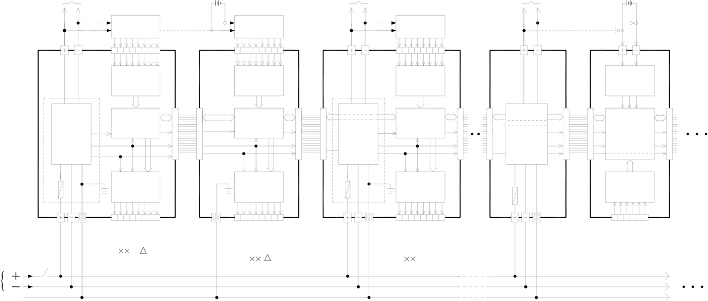
The schematic diagram of DC power supply in main/expansion unit is shown below. Also be cautious about the
following:
Please follow the wiring schemes regulated by local national standards to choose single-pole switch (break 24V+) or
double-pole switch (break both 24V+ and 24V−) in order to turn on or off DC input power.
Wiring of 24V+ input power must be connected to the terminal labeled by + , while the 24V− end is connected to
the – terminal, Please use wires with diameters of 1mm2~2mm2.
The G terminals on main unit and all digital expansion units/modules must be connected to the EG (Earth
Ground) terminal on main power system according to the scheme shown in the following figure, using wire diameters
larger than 2mm2.
|
•Warning |
Output of 24VDC power for input circuit cannot be connected in parallel with other powers, in which the conflict
between two sets of power will decrease their lifetime or cause immediate damage. This will induce unexpected
malfunction of PLC and cause serious or even deadly damage to people or equipment.
|
12 or 24VDC |
24VDC output |
24VDC |
24VDC output |
24VDC output |
24VDC |
|||||||
|
(for Sensor) |
external power |
(for Sensor) |
(for Sensor) |
external power |
||||||||
|
input / |
OR |
input / |
input / |
OR |
||||||||
|
Sensor |
Sensor |
|||||||||||
|
OUT |
Input |
OUT |
OUT |
IN |
||||||||
|
SPW24 |
Input |
SPW24 |
Input |
CONVERTER |
||||||||
|
(DC-DC) |
||||||||||||
|
-D24 |
control |
-D24 |
24V 0V |
|||||||||
|
24V 0V |
24V 0V |
|||||||||||
|
DC-DC |
5V |
CPU |
DC-DC |
5V |
control |
|||||||
|
Power |
DC-DC |
5V |
control |
|||||||||
|
Supply |
Output |
Power |
Power |
|||||||||
|
0V |
Supply |
0V |
Supply |
0V |
||||||||
|
24V |
24V |
24V |
||||||||||
|
F |
Output |
F |
Output |
F |
AI |
|||||||
|
Main unit |
Expansion module |
Expansion unit |
Expansion |
Expansion module |
||||||||
|
(FBS- M -D) |
power supply |
(FBS-6AD, 2DA, |
||||||||||
|
(FBS- ) |
(FBS- XY-D24) |
|||||||||||
|
SW |
(FBS-EPW-D24) |
6TC,6RTD…) |
||||||||||
power
PE
|
5.3 Residual Capacity of Main/Expansion Unit & Current Consumption of Expansion Module |
Besides its own circuits usage, the residual capacities of three sets of built-in power supply of main/expansion unit are big enough for other expansion modules usage. In addition, the expansion power (FBS-EPW) module can also provides the power for expansion modules usage. As each model of the main/expansion unit has AC/DC power or modules, it has different residual capacity, various models of expansion modules also consume different amounts of current. In practice, one has to consider the match between the two to avoid overload in any of the three sets of output power. In the following, the worst case of the available residual capacity in each main/expansion unit and the maximum power consumption of expansion modules are described below spare.
|
5.3.1 Residual Capacity of Main/Expansion Unit |
|
Model |
Extra Capacity |
5VDC(logic circuit) |
Output Power |
|||
|
24VDC(output circuit) |
24VDC(input circuit) |
|||||
|
-output communication block |
||||||
|
-output expansion cable- |
-output terminal block- |
|||||
|
or expansion cable- |
||||||
|
AC |
Main |
FBS-10/14MA |
- |
340mA |
||
|
300mA |
||||||
|
FBS-20MA |
753 mA |
335mA |
310mA |
|||
|
FBS-24MA |
722 mA |
325mA |
295mA |
|||
|
FBS-32MA |
712 mA |
315mA |
262mA |
|||
|
FBS-40MA |
688 mA |
295mA |
244mA |
|||
|
FBS-60MA |
644 mA |
255mA |
190mA |
|||
|
FBS-10/14MC |
300 mA |
- |
340mA |
|||
|
FBS-20MC |
753 mA |
335mA |
310mA |
|||
|
P |
Unit |
|||||
|
FBS-24MC |
722 mA |
325mA |
295mA |
|||
|
O |
||||||
|
FBS-32MC |
712 mA |
315mA |
262mA |
|||
|
W |
||||||
|
688 mA |
295mA |
244mA |
||||
|
FBS-40MC |
||||||
|
E |
||||||
|
FBS-60MC |
644 mA |
255mA |
190mA |
|||
|
R |
||||||
|
Expansion |
FBS-20MN |
710mA |
310mA |
325 mA* |
||
|
FBS-32MN |
670mA |
297mA |
280 mA* |
|||
|
FBS-44MN |
627 mA |
276 mA |
250 mA* |
|||
|
FBS-24XY-◎ |
948 mA |
350mA |
337mA |
|||
|
FBS-40XY-◎ |
918 mA |
320mA |
292mA |
|||
|
Unit |
||||||
|
FBS-60XY-◎ |
880 mA |
280mA |
238mA |
|||
|
DC |
FBS-10/14MA-D24 |
300mA |
- |
270mA |
||
|
FBS-20MA-D24 |
753mA |
Total295mA |
||||
|
FBS-24MA-D24 |
722mA |
Total270mA |
||||
|
FBS-32MA-D24 |
712mA |
Total227mA |
||||
|
P |
Main |
FBS-40MA-D24 |
688mA |
Total 189mA |
||
|
FBS-60MA-D24 |
644mA |
Total 95mA |
||||
|
O |
Unit |
|||||
|
FBS-10/14MC-D24 |
300mA |
- |
270mA |
|||
|
W |
||||||
|
FBS-20MC-D24 |
753mA |
Total 295mA |
||||
|
E |
||||||
|
FBS-24MC-D24 |
722mA |
Total 270mA |
||||
|
R |
||||||
|
FBS-32MC-D24 |
712mA |
Total 227mA |
||||
|
FBS-40MC-D24 |
688mA |
Total 189mA |
||||
|
644mA |
Total 95mA |
|||||
|
FBS-60MC-D24 |
||||||
|
FBS-20MN-D24 |
710mA |
Total 285mA* |
||
|
FBS-32MN-D24 |
670mA |
Total 227mA* |
||
|
FBS-44MN-D24 |
627mA |
Total 176mA* |
||
|
Expansion Unit |
FBS-24XY–◎ |
948mA |
Total 337mA |
|
|
FBS-40XY–◎ |
918mA |
Total 262mA |
||
|
FBS-60XY–◎ |
880mA |
Total 168mA |
z In the above table, the residual capacity is calculated according to the most power-consuming model (for example, MCT) of in each main/expansion unit by its I/O point number, under the maximum load condition (with both DI and DO ON). The basic units for calculation are 7.5mA /PT for high/medium speed DI, 4.5mA/PT for low speed DI (Ultra high speed DI does not use the 24VDC power in input circuit), 10mA/PT for high speed DO, 7.5mA/PT for medium speed DO, and 5mA for low speed DO and relay output. (excluding the SSR model).
z See Sections 5.1 and 5.2 for the residual capacity of expansion power (-EPW-AC and -EPW-D24)
|
•Warning |
|
Either for the built-in power supply of the main/expansion unit or the expansion power supply for the expansion unit, the total amount of current cannot exceed the value listed in the above table. Any violation will cause a voltage drop by overloading the power supply, or intermittent powered with the supply in protection mode, either of which will result in unexpected action of PLC and cause harm to people or damage to equipment. |
|
5.3.2 Maximum Current Consumption of Expansion Module |
Without its own power supply, expansion modules must be supported by the main/expansion unit, expansion power, or
external power supply (24VDC input circuit alone). The following table lists the maximum consumption current of each
expansion module.
|
Current |
5VDC Logic Circuit |
24VDC Output Circuit |
24VDC Input Circuit |
Model
|
FBS-24XY |
54 mA |
-input expansion cable- |
85mA |
–input terminal block— |
|
63mA |
||||
|
FBS-40XY |
83 mA |
136mA |
108mA |
|
|
FBS-60XY |
119 mA |
124mA |
162mA |
|
|
FBS-8XY |
30 mA |
34mA |
18mA |
|
|
FBS-8X |
30 mA |
- |
36mA |
|
|
FBS-8Y |
29 mA |
68mA |
- |
|
|
36mA |
||||
|
FBS-16XY |
40 mA |
68mA |
||
|
FBS-16Y |
40 mA |
136mA |
- |
|
|
90mA |
||||
|
FBS-20X |
35 mA |
- |
||
|
FBS-24X |
54 mA |
- |
108mA |
|
|
- |
||||
|
FBS-24YT |
66 mA |
- |
||
|
FBS-32DGI |
14 mA |
- |
36mA |
|
|
- |
||||
|
FBS-7SG1 |
24 mA |
213 mA |
||
|
FBS-7SG2 |
24 mA |
- |
396 mA |
|
|
- |
||||
|
FBS-6AD |
25 mA |
53 mA |
||
|
FBS-2DA |
33 mA |
- |
90 mA |
|
|
- |
||||
|
FBS-4DA |
35 mA |
137 mA |
||
|
FBS-4A2D |
35 mA |
- |
103 mA |
|
|
- |
||||
|
FBS-2TC |
30 mA |
21 mA |
||
|
FBs-6TC |
30 mA |
- |
29 mA |
|
|
- |
||||
|
FBS-6RTD |
32 mA |
16 mA |
||
|
FBS-16TC |
30 mA |
- |
58 mA |
|
|
- |
||||
|
FBS-16RTD |
32 mA |
19 mA |
||
|
FBs-6NTC |
33 mA |
- |
16 mA |
|
FBs-2A4TC |
39 mA |
- |
52 mA |
|
|
FBs-2A4RTD |
39 mA |
- |
32 mA |
|
|
FBs-B4AD |
25 mA |
- |
- |
|
|
FBs-B2DA |
223 mA |
- |
- |
|
|
FBs-B2A1D |
158 mA |
- |
- |
|
|
Voice |
FBs-VOM |
500 mA |
- |
- |
|
Special |
FBs-4PT |
25 mA |
- |
82 mA |
|
FBs-1LC |
32 mA |
- |
48 mA |
|
|
FBS-CB2 |
13 mA |
- |
- |
|
|
FBS-CB22 |
26 mA |
- |
- |
|
|
FBS-CB5 |
51 mA |
- |
- |
|
|
FBS-CB55 |
95 mA |
- |
- |
|
|
FBS-CB25 |
55 mA |
- |
- |
|
|
FBs-CBE |
50 mA |
|||
|
FBS-CM22 |
18 mA |
- |
- |
|
|
FBS-CM55 |
95 mA |
- |
- |
|
|
FBS-CM25 |
70 mA |
- |
- |
|
|
FBS-CM25E |
110 mA |
- |
- |
|
|
FBS-CM55E |
120 mA |
- |
- |
|
|
FBS-CM25C |
- |
- |
41 mA |
|
|
FBS-CM5R |
- |
- |
26 mA |
|
|
FBS-CM5H |
- |
- |
135 mA |
|
|
FBs-BDAP |
47 mA |
- |
- |
|
|
FBs-BPEP |
58 mA |
- |
- |
|
|
FBS-DAPB |
- |
- |
75 mA |
|
|
FBS-DAPC |
193 mA |
- |
- |
|
|
FP-08 |
125 mA |
- |
- |
|
z |
The above table lists the required current for the maximum consumption in each expansion module. The 24VDC |
input circuit consumes 4.5mA less per point of OFF state DI in DI/O module, while the 24VDC output circuit consumes 5mA less per point of OFF state DO. The effect of power consumption variation regarding the ON/OFF state of DI/DO of expansion modules other than DI/O are less significant and can be neglected.
z The effect of residual capacity variation regarding the ON/OFF state of DI/DO for 5VDC logic circuit can be neglected.
|
5.3.3 Calculation Example of Power Capacity |
Power module selection is depending on the sum of current consumption of all modules. Therefore, user must know the current consumption of each module. Please refer to the above table, which has the maximum current consumption of each expansion module.
Before power module selection, we need to calculate the total current consumptions. Calculations need to be divided into two sections, DC5V (Bus Power) current consumption and DC24V (Bus Power) current consumption.
User must consider the match between power and expansion modules cannot cause BusPower output power of any one group of overload use.
Example 1: The below diagram is a system modules, try to calculate the power supply used of the system.
|
FBs- |
FBs- |
FBs- |
FBs- |
FBs- |
FBs- |
|
CM55E |
B2DA |
24MC |
60XYR |
16YR |
6AD |
Unit : mA
|
Result |
|||||||
|
Internal 5VDC logic power supply |
-120 |
-223 |
+722 |
-119 |
-40 |
-25 |
+195 (OK) |
|
Internal 24VDC logic power supply |
- |
- |
+325 |
-124 |
-136 |
- |
+65 (OK) |
|
External 24VDC Sensor power supply |
- |
- |
+295 |
-162 |
- |
-53 |
+80 (OK) |
Result: (1) First calculate current consumption of internal 5VDC logic power supply +722mA – 120mA – 223mA – 119mA – 40mA – 25mA = +195 mA (OK)
(2) And then calculate current consumption of internal 24VDC logic power supply +325mA – 124mA – 136mA = +65 mA (OK)
(3) Calculate current consumption of external 24VDC Sensor power supply +295mA – 162mA – 53mA = +80 mA (OK)
In conclusion, the total current consumption of the above five modules cannot exceed the total current consumption of the main unit, so do not need to expand any power supply module.
Example 2: The below diagram is a system modules, try to calculate the power supply used of the system.
|
FBs- |
FBs- |
FBs- |
FBs- |
FBs- |
FBs- |
FBs- |
Unit : mA |
|
CM55E |
B2DA |
60XYR |
16YR |
16YR |
6AD |
||
|
24MC |
|||||||
|
Result |
||||||||
|
Internal 5VDC logic power supply |
-120 |
-223 |
+722 |
-119 |
-40 |
-40 |
-25 |
+155 (OK) |
|
Internal 24VDC logic power supply |
- |
- |
+325 |
-124 |
-136 |
-136 |
- |
-71 (overload) |
|
External 24VDC |
- |
- |
+295 |
-162 |
- |
- |
-53 |
+80 (OK) |
Result: (1) First calculate current consumption of internal 5VDC logic power supply +722mA – 120mA – 223mA – 119mA – 40mA – 40mA – 25mA = +155 mA (OK) (2) And then calculate current consumption of internal 24VDC logic power supply +325mA – 124mA – 136mA – 136mA = -71 mA (overload)
(3) Calculate current consumption of external 24VDC Sensor power supply +295mA – 162mA – 53mA = +80 mA (OK)
In conclusion, the total current consumption of internal 24VDC logic power supply of above six expansions exceeds power capacity of the main unit, so needs to expand power supply module as in example 3.
Example 3: The below diagram is a system modules, try to calculate the power supply used of the system.
|
FBs- |
FBs- |
FBs- |
FBs- |
FBs- |
FBs- |
FBs- |
FBs- |
|
CM55E |
B2DA |
24MC |
60XYR |
16YR |
6AD |
EPW-AC |
16YR |
Unit : mA
|
(1) |
Result |
(2) |
Result |
Internal 5VDC
|
logic power |
-120 |
-223 |
+722 |
-119 |
-40 |
-25 |
+195 (OK) |
400 |
-40 |
+360(OK) |
supply
Internal 24VDC
|
logic power |
- |
- |
+325 |
-124 |
-136 |
- |
+65 (OK) |
250 |
-136 |
+114 (OK) |
supply
External 24VDC
|
Sensor power |
- |
- |
+295 |
-162 |
- |
-53 |
+80 (OK) |
250 |
- |
+250 (OK) |
supply
Result: (1) First calculate the current consumption of expansion modules which provided from the main unit.
current consumption of internal 5VDC logic power supply
+722mA – 120mA – 223mA – 119mA – 40mA – 25mA = 195mA (OK)
current consumption of internal 24VDC logic power supply
+325mA – 124mA – 136mA = 65 mA (OK)
current consumption of external 24VDC Sensor power supply
+295mA – 162mA – 53mA = 80 mA (OK)
(2) then calculate the current consumption of expansion modules which provided from expansion power supply module
current consumption of internal 5VDC logic power supply
+400mA – 40mA = +360 mA (OK)
current consumption of internal 24VDC logic power supply
+250mA – 136mA = +114 mA (OK)
current consumption of external 24VDC Sensor power supply
+250mA – 0mA = +250 mA (OK)
In conclusion, add one expansion power supply(FBs-EPW-AC),in this way it can satisfy the total current consumption of six expansion modules.
|
5.4Requirement of Power Sequence in Main Unit & Expansion Unit/Module |
When the power is on, the FBS-PLC main unit first detects the type and number of expansion unit/module attached to its expansion interface and get the actual I/O configuration. Therefore, while the main unit performs detection, the power in expansion unit/module should be already UP, otherwise, the detected I/O configuration will not correct. Namely, the power of expansion unit/module should be ON simultaneously or even earlier. There will be no time sequence error when main unit/expansion unit/module are connected together to one power. If the expansion unit and main unit powered by different powers (or the same power but different switches), or external power supply is used for expansion modules, time sequence of both powers should be considered. To solve the problem of the expansion unit/module power not get ready before main unit power does, FBS-PLC provides a special R4150 register which can delay the detection time of I/O configuration. The time base of R4150 is 0.01sec with a default value of 100 (namely a 1sec delay), which can be set from 100~500 (1~5sec), as shown in the figure below. If the expansion unit power cannot be UP within 1sec after main unit power is ON, the R4150 time needs to be set longer to delay the detection by CPU. It cannot exceed 5sec, however, otherwise the configuration of expansion interface cannot be detected.
|
0 |
1 |
5 |
|
sec秒 |
秒sec |
sec秒 |
Main Unit Power 主機電源

|
擴充機(模組)電源Expansion Unit (Module) Power
No adjustment 無需調整Adjustment 需調整R4150 |
Unable to detect 無法偵測 |
|
|
required |
requiredR4150 |
|
Tip: press ← → to switch chapters, Ctrl+K to search