|
•Warning |
|
During maintenance, be sure to turn off the input power of PLC in case the actions to touch any terminal on PLC, or insert and extract accessories (e.g., expansion ribbon cables) is required. Otherwise, electric shock, short circuit, damaged PLC or PLC malfunction will be caused if the power is on. |
|
8.1Inspection After Wiring and Before First Time Power on |
1. Before power on, clean all unnecessary objects such as iron chippings and screws, and remove the dust cover
sheet that surround the FBS-PLC.
2. Make sure that the input power and PLC required power is of the same type. When input power is AC power,
please pay attention to connect the hot wire (L) to the “L” terminal on PLC and the ground wire (N) to the “N”
terminal. Mistakenly connect to DC powered PLC or to terminals other than “L” and “N” will result in electric shock,
serious damage or malfunction.
3. Make sure the load power and PLC output circuits are consistent. Connection of AC power to transistor output or
DC power to TRIAC output will damage PLC or result in malfunction.
4. Make sure the DC24V input and polarities of SINK/SOURCE in transistor output are consistent with those of your
existing wiring. Any mismatch will result in failure of PLC input and damage to the output circuit.
8.2Test Run and Monitoring
The FBS-PLC provides a convenient feature to Disable/Enable the I/O points by whole or individually. Namely, while PLC performs the normal logic scan operation and I/O refreshment, it does not update the status of the disabled input points according to the actual external input. For the disabled output points, the result of logic scan can’t override the disable status of outputs, only the user can force the state to ‘on’ or ‘off’ in order to simulate its operation. The user only needs to utilize the disable function combined with Monitor to achieve simulating the input or output via FP-08 or WINPROLADDER and observe the result. Upon the finish the simulation, revert all the inputs or outputs to Enable state will bring back normal operation. Refer the instructions of WINPROLADDER or FP-08 for the operation of RUN/STOP PLC, Disable/Enable I/O and monitoring of I/O status and content of register.
|
•Warning |
|
The disable function is to let the input or output status out of PLC program control and switched to the control of the user (tester) to freely set the disabled input or output to be ON or OFF. In normal PLC operation, when dealing with input or output with safety issues (such as upper/lower limit of detected input or output emergency stop), the user must make sure whether it can be disabled or overridden to ON/OFF before starting the disable or override control, to avoid damage to equipment or harm to people. |
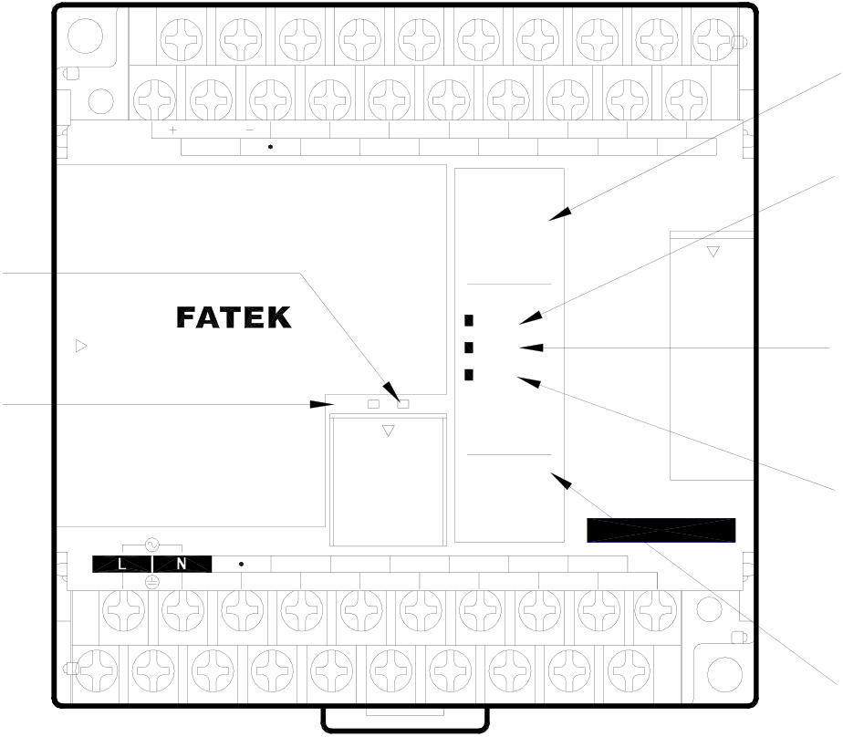
|
8.3LED Indicators on PLC Main Unit and Troubleshooting |
|
Receive Indicator “RX” 接收指示 "RX" |
max. |
24V OUT |
X0 |
X1 |
X2 |
X3 |
X4 |
X5 |
X6 |
X8 |
X9 |
X10 |
X11 |
X12 |
X13 |
輸入狀態指示 "Xn" Input Status Indicator “Xn” |
||
|
400mA |
S/S |
TX |
RX |
X7 |
Power Indicator “POW” 電源指示 "POW" |
|||||||||||||
|
0 |
I |
2 |
3 |
|||||||||||||||
|
4 |
5 |
6 |
7 |
|||||||||||||||
|
8 |
9 |
I0 |
II |
|||||||||||||||
|
PROGRAMMABLE |
||||||||||||||||||
|
I2 |
I3 |
|||||||||||||||||
|
Operation Indicator “RUN” |
||||||||||||||||||
|
INX ( ) |
||||||||||||||||||
|
POW |
||||||||||||||||||
|
Transmit Indicator “TX” 傳送指示 " TX" |
RUN |
|||||||||||||||||
|
CONTROLLER |
ERR |
|||||||||||||||||
OUTY ()
|
IN |
AC100~240V |
Y1 |
C2 |
PORT0 |
Y4 |
C4 |
0 |
I |
2 |
3 |
Y7 |
FBs-24MCR2-AC |
Error Indicator “ERR” 錯誤指示 "ERR" |
|
|
4 |
5 |
6 |
7 |
|||||||||||
|
8 |
9 |
|||||||||||||
|
C0 |
Y0 |
Y2 |
Y5 |
C6 |
Y6 |
Y8 |
Output Status Indicator “Yn” or |
|||||||
|
Y3 |
Y9 |
|||||||||||||
|
error Indicator (when “ERR” 輸出狀態指示 "Yn" |
||||||||||||||
|
occurs) 或錯誤碼指示 (當有"ERR"發生時) |
||||||||||||||
Power Indicator〝POW〞
After the PLC is power on, with correct power source and wiring, the〝POW〞LED indicator in the middle of the PLC nameplate will turn on, indicating that power supply is normal. If the indicator is not on, please try to temporarily remove the wiring of 24VDC output power for Sensor. If the LED is back to normal, it means that the load on the power for the 24VDC input circuit is too large so that PLC enters overload low voltage protection mode. (When PLC enters overload low voltage protection mode, “POW” LED is off and there are slight and intermittent low frequency hissing sounds, from which one can tell if the 24VDC power is overloaded or shorted.)
When the above method still cannot turn on the〝POW〞LED, if it is confirmed that correct power input exists between PLC power input L/N terminals or +/- (DC power), please send the unit to your local distributor for repair.
Operation Indicator〝RUN〞
As long as the CPU is working properly, in the STOP state, this indicator will go on and off for 2 seconds, respectively. When it’s in the RUN state, the indicator will go on and off for 0.25 seconds, respectively. To make PLC enter into Run state, or switch from RUN to STOP state, it has to be done through the programmer (FP-08 or WINPROLADDER). Once PLC is set to RUN or STOP, it will keep that state even after power off. The only exception is, when using the ROM PACK, no matter if it’s running or stopped before power off, PLC will automatically enter RUN state (with correct ROM PACK syntax check) when power is back. In normal operation of PLC upon errors (e.g., errors in WDT timer and program), PLC will automatically switch to STOP state and light the〝ERR〞error indicator. If it is a minor error, the RUN state can be resumed as long as the power is back after an outage. In case of serious errors, the PLC cannot be operated again with the programmer until the problem is solved. If PLC cannot be resumed to RUN state after all, please send it to your local distributor for repair.
Error Indicator〝ERR〞
In normal PLC operation, either in RUN or STOP state, this indicator will not show any signal (off). If it is on, it means that the system has an error (e.g., WDT time-out, program error, communication error, etc.)
If it is constantly on, please reset the power. If the situation is still the same, it implies a hardware failure in CPU and has to be sent to the distributor for repair.
When the ERR indicator flashes with a 0.5 sec interval, it means that some anomaly occurs to PLC. At the same time, status indicators Y0~Y3 switch to serve as indications of 15 error codes (the corresponding outputs are disabled), which
are described in the following:
|
Y3 |
Y2 |
Y1 |
Y0 |
Error Code |
Description |
|
0 |
0 |
0 |
1 |
1 |
Application program contains the functions not supported by this CPU |
|
0 |
0 |
1 |
0 |
2 |
Mismatch of PLC ID VS. program ID |
|
0 |
0 |
1 |
1 |
3 |
Checksum error in LADDER program |
|
0 |
1 |
0 |
0 |
4 |
System STACK abnormal |
|
0 |
1 |
0 |
1 |
5 |
Watch-Dog occurs |
|
0 |
1 |
1 |
0 |
6 |
Exceed main unit I/O |
|
0 |
1 |
1 |
1 |
7 |
Syntax check error occurs |
|
1 |
0 |
0 |
0 |
8 |
Expansion I/O modules over limit |
|
1 |
0 |
0 |
1 |
9 |
Expansion I/O points over limit |
|
1 |
0 |
1 |
0 |
10 |
System FLASH ROM CRC error |
|
1 |
0 |
1 |
1 |
11 |
Reserved |
|
1 |
1 |
0 |
0 |
12 |
Reserved |
|
1 |
1 |
0 |
1 |
13 |
Reserved |
|
1 |
1 |
1 |
0 |
14 |
Reserved |
|
1 |
1 |
1 |
1 |
15 |
Reserved |
|
Indicator on Transmit/Receive of Built-In Communication Port (Port0) “TX”、“RX” |
These two LED indicators are used for the status of transmit/receive of the built-in communication port (Port0). The RX indicator (green) is for indication when PLC receives external signals, while the TX indicator (red) is for indication when PLC transmits signals, both of which are very helpful in monitoring communication condition and debugging. When PLC communicates with external equipment (computer, programmer, intelligent peripherals, etc.), Port0 in FBS-PLC can only be used in slave mode (Port1~4 can be used in master mode). Therefore, during its operation, PLC must first receive external signals (RX on) before it can transmit signals back to external equipment (TX on now). When the communication is fail, one can tell if it’s PLC is not receiving signals or PCL is not replying by looking at the these two indicators. The currents in these two LED are constant and their lighting duration is proportional to the reception or transmission time. The more received/transmitted data or the slower (bps) reception/transmission, the longer the reception/transmission time and so is the indication time (brighter visually). If in high speed but small amount of data, only short and dim brightness is observed. Therefore, the communication condition can be easily distinguished by these two indicators.
Indicator of Input Status〝Xn〞
When external input Xn is ON, the corresponding LED indicator Xn will be on, otherwise it will be off. If it fails to respond to external input, please check if the terminal wiring is securely connected, or measure the voltage between〝Xn〞and common〝C〞to see if it has a change of 0V/22V with ON/OFF of input. If it does, it means that an error occurs in PLC input circuit or LED indicator. Or you can locate the problem by using the monitor mode of the programmer to check if this input status works correspondingly with the external input state.
Indicator of Output Status〝Yn〞
When the Yn output of PLC is ON, its corresponding output indicator will also be on and its external load will be ON. If ON/OFF condition of external load is inconsistent with output indicator, please check the wiring of the load, power, and terminal for secure connection. If the connection is good, then it should be the PLC output component failure. The main reasons to cause the output component failure are:
1. Overload or short circuit that burns output component and results in permanent open or short circuit.
2. Not overloaded, but Inrush current from capacitive load welds relay contacts at〝ON〞, resulting in permanent ON, or burns transistor or TRIAC, resulting in permanent ON or OFF.
3. Not overloaded, but the inductive load without proper Snubber circuit causes high voltage sparks between relay contact at〝OFF〞and generate carbon deposition, which separates contacts and causes permanent OFF or intermittent ON/OFF, or punches through transistor or TRIAC with high voltage, resulting in permanent ON or OFF.
8.4Maintenance
FBS-PLC itself has no user serviceable parts and all maintenance has to be conducted by professional personnel. During use, in case of any defective unit, please first try to find out the defect from the above error codes on the main unit, followed by performing maintenance over the entire unit or on the Board level. Send the unit that is still not functioning well to local distributors.
|
8.5The Charge of Battery & Recycle of Used Battery |
Every FBs –PLC main units have inside one re-chargeable lithium battery to safely maintain program and data during main power shut down. Each lithium battery was fully charged when the FBs-PLC ship out from the factory capable to retain program and data at least 6 months. There is risk to miss program and data when battery exhaust over 6 months, the users should mind the date marked on each FBs-PLC.
In case exceeding 6 months, users can do battery re-charging by themselves through keeping FBs-PLC be powered for over 12 hours then more 6 months can work smoothly on the data saving.
|
•Warning |
||
|

Tip: press ← → to switch chapters, Ctrl+K to search