The function of the data access board (FBs-BDAP) is mainly used for displaying and setting of the calendar time and discrete and register data of PLC. For the discrete elements, user can perform the disable or enable function also can set or reset its state. For the registers, the contents can be set and displayed in unsigned or signed decimal format and hexadecimal format. This unit should be mounted on the PLC main unit while install.
1.1 FBs BDAP Function Description
There are some notations were referred in following sections and described at below:
【T】: Current value and on/off status of timer
【C】: Current value and on/off status of counter
【D】: Data register(D type)
【R】: Data register(R type)
【F】: File register
【X】: Discrete Input (DI)
【Y】: Discrete Output(DO)
【M】: Internal relay
【S】: Step relay
|
Feature |
Description |
|
|
Cal |
Calendar Function* 1 |
|
|
Display |
Display current Year, Month, Date, Hour and minute data |
|
|
Setting |
Set Year, Month, Date, Hour and minute data |
|
|
Sta |
Status Display Function |
|
|
Discrete Element |
Display the state and enable/disable status of X,Y,M,S element |
|
|
16 bit Register |
Display the current value of T, C, D, R, F register. Three display formats (unsigned/signed/hexadecimal) can be chosen. |
|
|
32 bit Register |
Display the current value of C, D, R, F register. Three display formats (unsigned/signed/hexadecimal) can be chosen. |
|
|
Force On/Off Function |
Force the state of X, Y, M, S to be On or Off |
|
|
Disable/Enable Function |
Control the state of X, Y, M, S to be enabled or disabled |
|
|
Reg Fun |
ister Content Modification ction |
|
|
16 bit Register |
Modify the current value of T, C, D, R, F register. Three display formats (unsigned/signed/hexadecimal) can be chosen. |
|
|
32 bit Register |
Modify the current value of C, D, R, F register. Three display formats (unsigned/signed/hexadecimal) can be chosen. |
|
|
Setting and Display of PLC Station Number Function |
Display and set the PLC station number. |
|
|
Force PLC Run/Stop Function |
Force the PLC to run or stop logic solving and I/O service. |
|
|
Access Protection Function |
Provide operator and supervisor password for protection |
|
1.2 FBs BDAP Display Legend
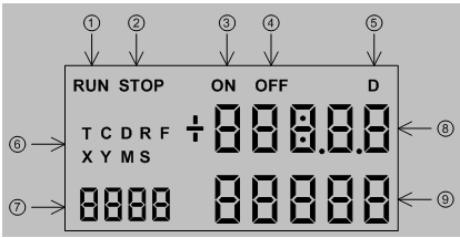
①“RUN” indicator. When the PLC is in running state, this symbol will be appeared.
②“STOP” indicator. When the PLC is in stop state, this symbol will be appeared.
③“ON” indicator. When the selected element is Timer or Counter, this symbol will be appeared when the corresponding state is on.
④“OFF” indicator. When the selected element is Timer or Counter, this symbol will be appeared when the corresponding state is off.
⑤“D” indicators. When the selected element is 32 bit register, the “D” symbol will be appeared.
⑥Element symbols for selection. There are nine element types can be chosen, those are T, C, D, R, F, X, Y, M and S.
⑦Reference number or year display, The sequence number of the selected element or the year part of the calendar.
⑧Value display or hour and minute display. For 16 bit register, it represents the current value of 16 bit content. For 32 bit register, it represents the portion of the number above 5t h digit (million) in decimal or MSB word in hexadecimal format. It also represents the state of discrete element or hour and minute part of the calendar.
⑨Value display or month and day display. For 32 bit register, it represents the lower 5 digit portion of the number in decimal or LSB word in hexadecimal format. It also represents the enable/disable state of discrete element or month and day part of the calendar.
1.3 FBs BDAP Operation Procedure
Operation Keypads: There are six keypads in total for operation.
|
ESC : Escape key |
||
|
OK |
: OK key |
|
|
- |
: “-” key |
|
|
+ |
: “+” key |
|
|
Æ |
: “Æ” key(shift right) |
|
|
Å |
: “Å” key(shift left) |
|
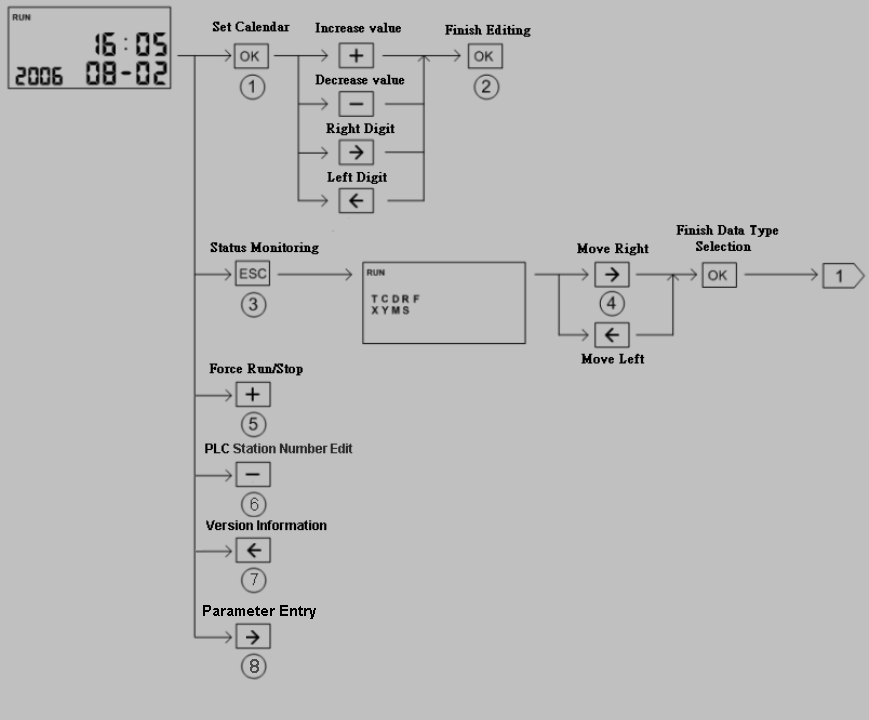
Default display mode: Calendar Display
|
○1Select the field to be changed, selected field will be blinked ○2Enter the new value ○3Enter status monitoring display screen ○4Use Å key、Æ key select the element type to be monitoring. The selected type will be |
blinked.
|
○5Under calendar display mode, press+key to force PLC stop or run |
⑥Under calendar display mode, press-key to display and modify the PLC station number
⑦ Under calendar display mode, pressÅkey, can display the firmware version of PLC
|
|
and BDAP. Under calendar display mode, pressÆkey, can enter the user parameter entry |

screen.
Note: No matter at which display screen, press <ESC> for 2 seconds will lead the screen
to calendar display.
Discrete Element Monitoring:
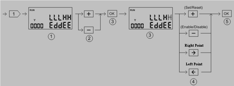
○1Discrete element(X、Y、M、S) display screen show five consecutive points of status at one time. The upper row is on/off status while the lower row is disable/enable status.
|
○2Element reference number adjust + key:Increase the reference number by 5 -key:Decrease the reference number by 5 ○3Enter the element status editing state. The selected point will be blinked. ○4Modification of element ON/OFF、Enable/Disable status + key:Change the ON/OFF status(toggle operation) -key:Change the Enable/Disable status(toggle operation) |
Æ key:Move cursor to the lower point to be edited(decrease the reference number)
Å key:Move cursor to the higher point to be edited(increase the reference number)
○5Finish the editing.
Timer/Counter Status Monitoring:
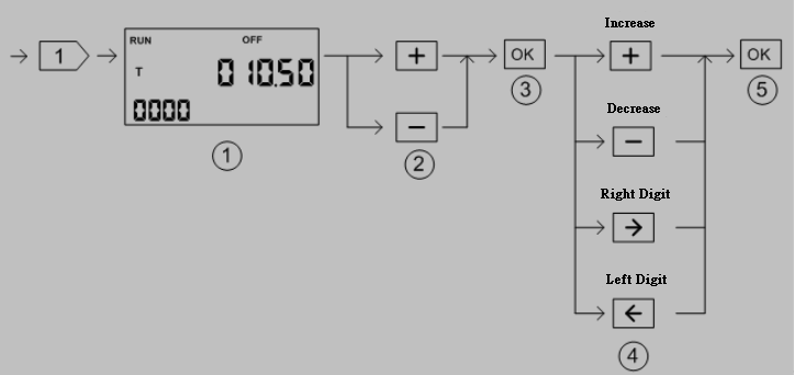
○1The current value ofT, C elementif reach the preset value will show”ON”, otherwise will show”OFF”
|
○2Reference number adjust + key:Reference number decreased by one -key:Reference number increased by one ○3Enter editing mode. The digit to be changed will be blinked. ○4Modify value + key:Increased by one -key:Decreased by one |
Æ key: Move to the right digit
Å key: Move to the left digit.
○5Finish the editing and increase the reference number by one and back to○
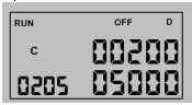
※ When monitoring the counter element, if the reference number is great than 200 then the display value will be in 32 bit format(C200~C255 are 32bit counter)
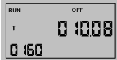
※ When monitoring the timer element, the decimal point of current value will be set accordingly.
Register Status Monitoring:
|
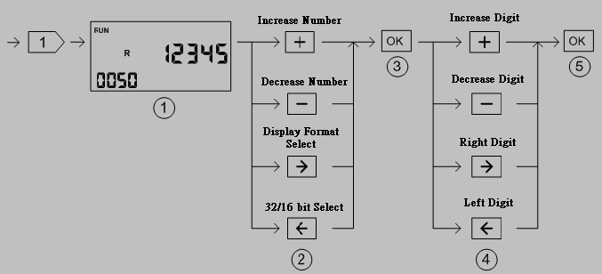
○1Default unsigned 16 bit decimal value display ○2Adjust the reference number and select the display format + key:Increase the reference number by one when 16 bit display format, by two |
when in 32 bit display format.
|
-key:Decrease the reference number by one when 16 bit display format, by two |
when in 32 bit display format.
Æ key: Display format selection. There are signed decimal, unsigned decimal and hexadecimal display format can
be selected. Each depression of Æ key can change the format once.
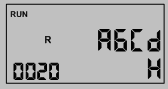 <16 bit hexadecimal display>
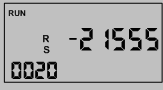 <16 bit signed decimal display>
Å key: 16 bit/32 bit display format selection, Each depression of Å key will toggle the
display format between these two modes.
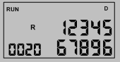 <32 bit unsigned decimal>
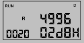 <32 bit hexadecimal display>
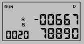 <32 bit signed decimal display>
○3Enter editing mode. The digit to be edited will be blinked.
|
○4Modify digit value + key: Increased by one -key: Decreased by one |
Æ key: Move cursor to the right digit
Å key: Move cursor to the left digit
○5Finish the editing and automatically point to the next available reference number then back to○
Password Access Protection:
In order to protect the PLC data from inadvertent modification by operating of the BDAP with irrelative person, there are two kinds of password can be setup. One is operator password, while the other is supervisor password. People should pass the operator password authentication before can access the parameter entry function. Supervisor password is required if intend to enter the PLC element status editing function.
These two passwords are stored in D register of PLC.
D3980 – Location to store operator password.
D3981 – Location to store supervisor password.
Valid password range 1 ~ 65535. Filled 0 value when corresponding password protection is disabled.
User Parameter Entry:
With this function, can access the M(discrete) and R register of PLC.
The scope of monitoring M and R register can be defined by the following D registers of PLC.
D3982 – Quantity of read only portion of R-parameter. The R-parameter at first portion can be configured as read only.
D3983 –Quantity of R-parameter, which include read only and read-writeable R-parameter. The valid value of this register is 0~999.
D3984 – Starting address of R-parameter. The valid value of this register is- 0~3839 and 5000 ~ 8071
D3985 – Quantity of M-parameter, The valid value of this register is 0~999.
D3986 – Starting address of M-parameter. The valid value of this register is 0~1911.
When the content of setup-register is invalid, the corresponding type of parameter will not be shown for selection.
Tip: press ← → to switch chapters, Ctrl+K to search