
As previously revealed in Chapter 12 that the FBs-PLC can support the "Ladder Program Control Interface" communication function for the applications of multi-drop FATEK CPU Link network or connecting with the intelligent peripherals through Port 1~Port 4.
The connection of FBs-PLC can through CLINK(FUN151), besides it support Modbus communication interface, too. Port1~Port 4 can be Modbus communication protocol master station by FUN150 to connect with the Modbus slave peripherals.
The RS-232 interface is for point to point connection, the RS485 interface is for long distance connection or multi-drop communication network
The FUN151 (CLINK) instruction provides MD0 to MD3 four kinds of instruction mode, that the MD3 mode is monopolized by Port 2 for “FATEK High Speed CPU Link Network” , the others are for “Ordinary Communication Link”.
The following list enlisted the description for the difference on various instruction modes for the CLINK instruction
|
Category |
Item |
Baud Rate |
Data Bit |
Transmitting |
Error detection |
Command |
|
code |
processing speed |
|||||
|
FUN151 |
High Speed LINK |
38.4K bps |
8-bit |
Binary code |
CRC-16 |
Immediately |
|
(MD3) |
| |
|||||
|
* Port 2 only |
921.6K bps |
|||||
|
(CLINK) |
Ordinary LINK |
4.8K bps |
7-bit or 8-bit |
ASCII code |
Checksum |
Processing |
|
| |
||||||
|
(MD0~MD2) |
||||||
|
during |
||||||
|
921.6K bps |
Adjustable |
|||||
|
* Port 1~Port 4 |
Housekeeping |
|||||
|
FUN150 |
Modbus |
4.8K bps |
7bit/8bit |
Binary |
CRC-16 |
Processing |
|
code |
||||||
|
when scan to |
||||||
|
| |
/ |
/ |
||||
|
Master |
FUN150 |
|||||
|
(M-BUS) |
ASCII |
Checksum |
||||
|
921.6K bps |
||||||
|
instruction |
||||||
|
Code |
|
13.1 Application for FUN151 Instruction |
|
13.1.1 Procedures for Usage |
Start
Hardware wiring to connect the various
stations (PLC, ASCII peripherals, etc.)
Set up the station number of the linking
stations and make a consistent
communication parameters setting for
these stations.
Fill in the value to the communication interface register (Rxxxx) of FUN151 (CLINK) if necessary; properly adjust the Time-out timer to detect
● Station number can be set to any one between 1 to 254 without replication.
● For communication parameters, please refer to the
description of "Communication Related Setting".
communication error, transaction delay
to meet slow response device , etc.
Write FUN151 instruction to PLC, which
serves as the master station or
performs communication sender/
receiver, and then fill the
communication program into the
register table assigned by operand SR.
FUN151 will then automatically send or
receive data according to the definition
of communication program. The user
can easily reach the various function
services of CLINK by accessing the
table like of communication program.
End
13.1.2 Explanation of Respective Modes and Application Program for FUN151
This section will base on the four instruction modes (MD0 to MD3) of FUN151 (CLINK) instruction to explain their
usages, with respective practical application program examples.








FBs-PLC LINK
|
FUN151 CLINK |
Convenient Instruction of FUN151: MD0 |
FUN151 CLINK |
||||||||||||||||||||||||||||||||||||||||||||||||||||||||||||||||||||||||||||||||||||||||||||||||||
|
||||||||||||||||||||||||||||||||||||||||||||||||||||||||||||||||||||||||||||||||||||||||||||||||||||
|
Descriptions
one of the slave station to get which type of data and save them to the master PLC, or from the master PLC to write which type of data to the assigned slave station. It needs only seven registries to make definition; every seven registers define one packet of data transaction. 5. When execution control 〝EN〞changes from 0→1 and both inputs “PAU” and “ABT” are 0, and if Port 1/2/3/4 hasn’t been controlled by other communication instructions [i.e. M1960 (Port1) / M1962 (Port2) / M1936 (Port3) / M1938 (Port4) = 1], this instruction will control the Port 1/2/3/4 immediately and set the M1960/M1962/M1936/M1938 to be 0 (which means it is being occupied), then going on a packet of data transaction immediately. If Port 1/2/3/4 has been controlled (M1960/M1962/M1936/M1938 = 0), then this instruction will enter into the standby status until the controlling communication instruction completes its transaction or pause/abort its operation to release the control right (M1960/M1962/M1936/M1938 =1), and then this instruction will become enactive, set M1960/M1962/M1936/M1938 to be 0, and going on the data transaction immediately. 6. While in transaction processing, if operation control “PAU” becomes 1, this instruction will release the control right (M1960/M1962/M1936/M1938 = 1) after this transaction. Next time, when this instruction takes over the transmission right again, it will restart from the next packet of data transaction. 7. While in transaction processing, if operation control “ABT” becomes 1, this instruction will abort this transaction immediately and release the control right (M1960/M1962/M1936/M1938 = 1). Next time, when this instruction takes over the transmission right again, it will restart from the first packet of data transaction. 8. While it is in the data transaction, the output indication “ACT” will be ON. 9. If there is error occurred when it finishes a packet of data transaction, the output indication “DN” & “ERR” will be ON. 10. If there is no error occurred when it finishes a packet of data transaction, the output indication “DN” will be ON. |
||||||||||||||||||||||||||||||||||||||||||||||||||||||||||||||||||||||||||||||||||||||||||||||||||||









FBs-PLC LINK
|
FUN151 CLINK |
Convenient Instruction of FUN151: MD0 |
FUN151 CLINK |
|||||||||||||||||||||||||||||||||||||||||||||||||||||
|
【Interface Signals】 Dedicated Relays and Registers for corresponding port :
1. Port Ready Indicator:This signal is generated from CPU. ON, it represents that port is free and ready. OFF, it represents that port is busy, data transaction is going. 2. Port Finished Indicator : This signal is generated from CPU. When the communication program completed the last packet of data transaction, this signal will be ON for one scan time (for successive data transaction). When the communication program completed the last packet of data transaction, this signal will be still ON (for single packet of data transmission) 3. Port Communication Parameters : 4. TX Delay & RX Time-out Span : The content of High Byte defines the transmission delay time between two packets of data transaction for CLINK instruction; its unit is 0.01 second (the default is 0). 5. Setting of RX Time-out Span D4043:
|
|||||||||||||||||||||||||||||||||||||||||||||||||||||||
FBs-PLC LINK
|
FUN151 CLINK |
Convenient Instruction of FUN151: MD0 |
FUN151 CLINK |
||||||||||||||||||
|
D4043:Setting the time unit in 0.01 or 0.1 second for RX time-out detection High Byte Low Byte
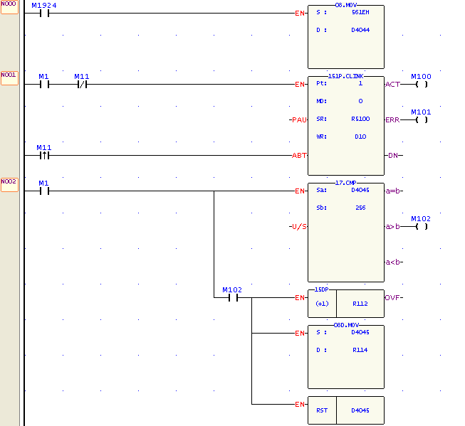
High Byte of D4043 ≠56H (Hex), time unit is in 0.01 second. High Byte of D4043 = 56H (Hex), Low Byte of D4043 defines the time unit; b1=0, Time-out timer in 0.01 second (Port 1) =1, Time-out timer in 0.1 second (Port 1) b2=0, Time-out timer in 0.01 second (Port 2) =1, Time-out timer in 0.1 second (Port 2) b3=0, Time-out timer in 0.01 second (Port 3) =1, Time-out timer in 0.1 second (Port 3) b4=0, Time-out timer in 0.01 second (Port 4) =1, Time-out timer in 0.1 second (Port 4) For example, D4043=560AH, it means time unit in 0.1 second for Port 1 & 3; but in 0.01 second for Port 2 & 4 If low byte of R4147=50, it means Port 1 has 5 seconds for RX time-out detection; 6. Edge Trigger Execution D4044:
High Byte of D4044=00H (Hex), Low Byte of D4044 defines the communication port; |
||||||||||||||||||||
FBs-PLC LINK
|
FUN151 CLINK |
Convenient Instruction of FUN151: MD0 |
FUN151 CLINK |
|||||||||
|
High byte of D4044=56H D4044:Setting of one edge trigger to execute one communication transaction or only one edge trigger then make continuous execution of communication transactions High Byte Low Byte
High Byte of D4044≠56H(Hex), one edge trigger to execute one communication transaction High Byte of D4044=56H(Hex), Low Byte of D4044 defines the communication port; b1=0, one edge trigger to execute one communication transaction (Port 1) =1, only one edge trigger then make continuous execution of communication transaction (Port 1) b2=0, same as the description of b1=0 (Port 2) =1, same as the description of b1=1 (Port 2) b3=0, same as the description of b1=0 (Port 3) =1, sane as the description of b1=1 (Port 3) b4=0, same as the description of b1=0 (Port 4) =1, same as the description of b1=1 (Port 4) zWR+0 & WR+1 of communication instruction will tell the communication result for each communication transaction if it is one edge trigger to execute one communication transaction Let the control input ABT be ON if it wants to stop the communication transaction |
|||||||||||
FBs-PLC LINK
|
FUN151 CLINK |
Convenient Instruction of FUN151: MD0 |
FUN151 CLINK |
||
|
||||
FBs-PLC LINK
|
FUN151 CLINK |
Convenient Instruction of FUN151: MD0 |
FUN151 CLINK |
|
|
||
FBs-PLC LINK
|
FUN151 CLINK |
Convenient Instruction of FUN151: MD0 |
FUN151 CLINK |
|
|
||
FBs-PLC LINK
|
FUN151 CLINK |
Convenient Instruction of FUN151: MD0 |
FUN151 CLINK |
||
|
||||
FBs-PLC LINK
|
FUN151 CLINK |
Convenient Instruction of FUN151: MD0 |
FUN151 CLINK |
|
|
||
FBs-PLC LINK
|
FUN151 |
Convenient Instruction of FUN151: MD0 |
FUN151 |
|
CLINK |
(Which makes PLC act as the master station in CPU LINK network through Port 1~4) |
CLINK |
Waveform of input control and output indication
M1960 …
M1962
M1936
M1938
|
ENU |
Transaction 0 |
… |
Transaction N |
|
ACT |
… |
||
|
Transaction 1…… |
ABT
FBs-PLC LINK
|
FUN151 CLINK |
Convenient Instruction of FUN151: MD0 |
FUN151 CLINK |
||||||||||||||||||||||||||||||||||||||||
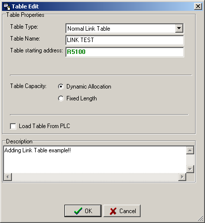
Click the “Link Table” Item which in project windows :
Link Table Æ Click right button and select “New Link Table”
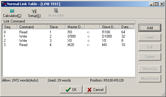
● Table Type : MD0 must be selected ”Normal Link Table”. ; MD3 must be selected ”High Speed Link Table”. ● Table Name : For modify or debug, you can give a convenient name. ● Table Starting address : Enter the address which is the starting register of communication table to store the data exchange list. ※To make it easy to edit, read, and maintain the communication program, we have extended following related instructions under FUN150 and FUN151. The use method is take focus on FUN150 or FUN151, and press the hotkey “Z”. When “Table Edit” windows appear, then you can edit the communication table. |
||||||||||||||||||||||||||||||||||||||||||


FBs-PLC LINK
|
FUN151 CLINK |
Convenient Instruction of FUN151: MD0 |
FUN151 CLINK |
||||||||||||||||||||||||||||||||||||||||||||||||||||||||||||
|
Explanation for operand SR
|
||||||||||||||||||||||||||||||||||||||||||||||||||||||||||||||


FBs-PLC LINK
|
FUN151 CLINK |
Convenient Instruction of FUN151: MD0 |
FUN151 CLINK |
||||||||||||||||||||||||||||||||||||||||||||||||||||||||||||||||||||||
Note : The data type for master and slave must be consistent. i.e. if the master station is any value between 0 to 5, the slave station must also be any value between 0 to 5; if the master station is any value between 6 to 13, the slave station must also be any value between 6 to 13.
Result code: 0, this transaction is successful. 2, data length error (data length is 0 or greater than 64 in one transaction). 3, command code error (command code is greater than 2). 4, data type error (data type is greater than 13, please refer to data type code). 5, reference number error (please refer to reference number). 6, inconsistence in data type (e.g. master station is 0~5 while slave is 6~13). A, no response from slave station (Time-out error). B, communication error (received error data). |
||||||||||||||||||||||||||||||||||||||||||||||||||||||||||||||||||||||||
FBs-PLC LINK
|
FUN151 CLINK |
Convenient Instruction of FUN151: MD0 |
FUN151 CLINK |
|||||||||||||||
|
● For easy programming and trouble shooting, the WinProladder provides the table editing environment to edit the communication table of FUN151 instruction; Key in the complete FUN151 instruction first and then move the cursor to the position of it, depressing the "Z" key, now comes the table editing environment. The user can create the new communication table or display the existed table under this friendly user interface operation.
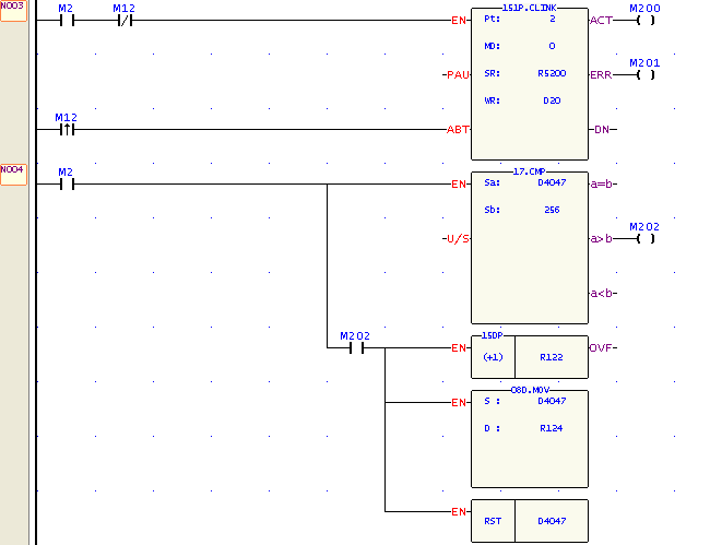
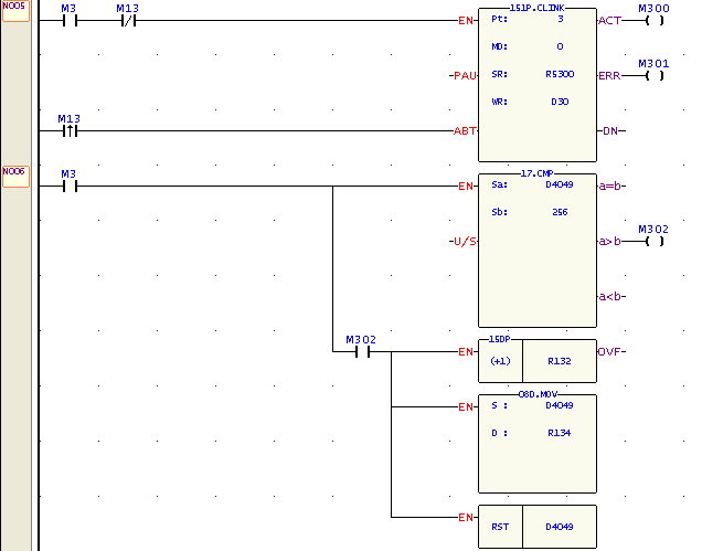
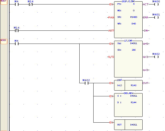
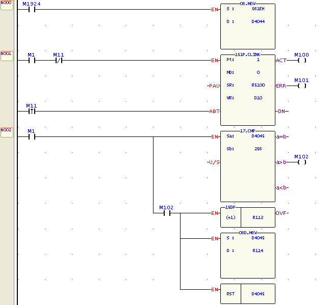
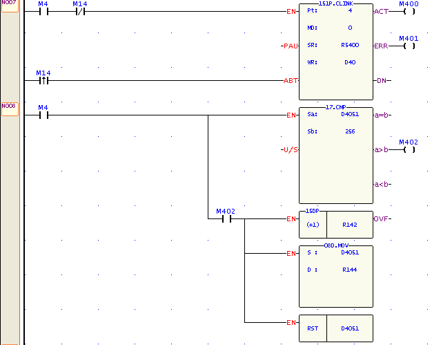
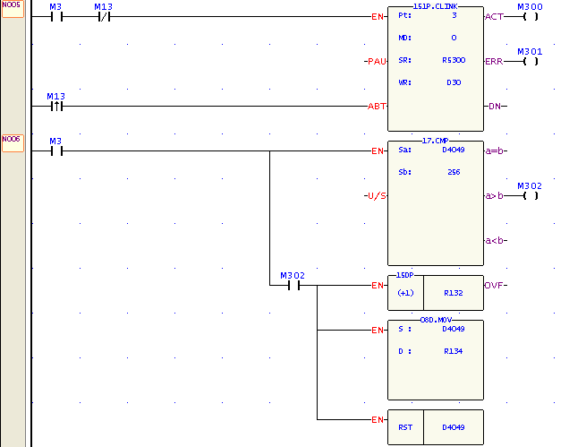
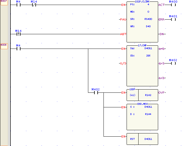
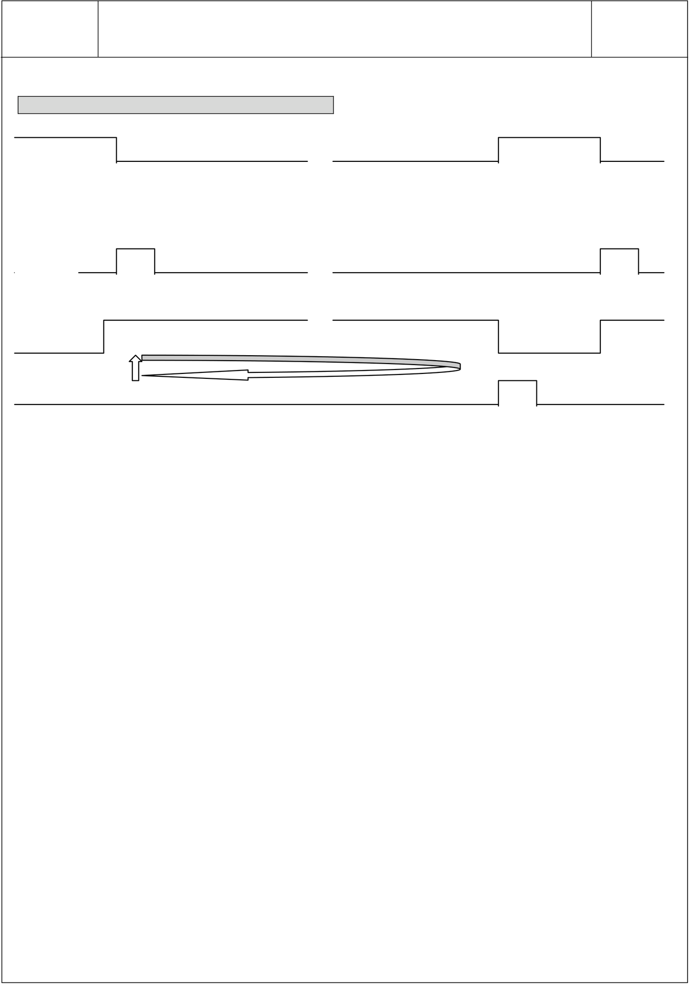
Explanation on program example When execution control M1/M2/M3/M4 = ON, and corresponding port is not occupied by other communication instruction (M1960、M1962、M1936、M1938 = ON), CLINK instruction will start the data transaction. The M1960、M1962、M1936、M1938 is OFF during data transaction, and when the transaction is finished, the M1960、M1962、M1936、M1938 becomes ON. Employ the OFF↔ON change of M1960、M1962、M1936、M1938 (FUN151 execution control 〝ENU〞•means starting) may automatically starts for every packet of data transaction successively (when the last packet of transaction is completed, it will automatically return to the first packet of transaction to obtain the automatic cycling transmission). ● Output Indicators :〝ACT〞ON:Transaction is in progress |
|||||||||||||||||

FBs-PLC LINK
|
FUN151 |
Convenient Instruction of FUN151: MD0 |
FUN151 |
|
CLINK |
(Which makes PLC act as the master station in CPU LINK network through Port 1~4) |
CLINK |
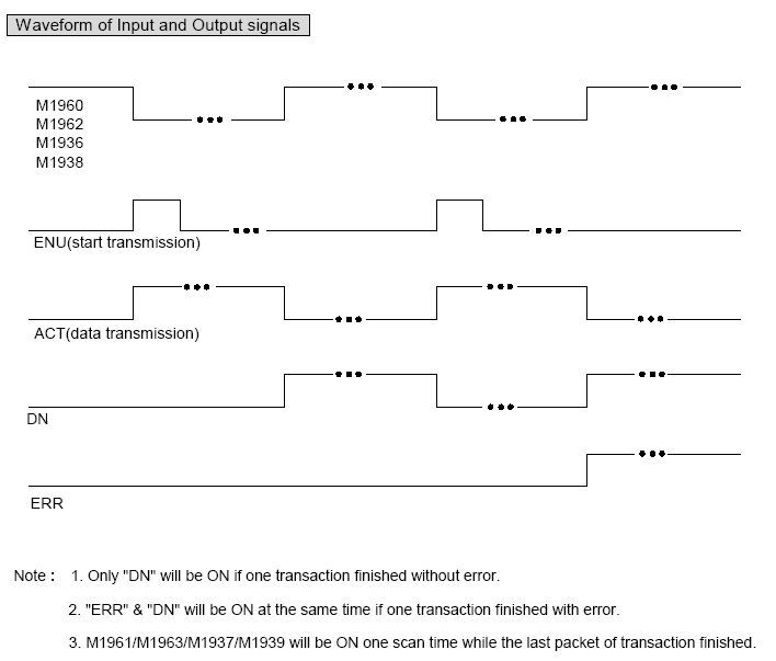
Waveform of Input and Output Signals
M1960
M1962
M1936
M1938
ENU(start transmission)
ACT(data transmission)
DN(Non-error)
ERR(Error occur)
Note : 1. Only "DN" will be ON if one transaction finished without error.
2. "ERR" & "DN" will be ON at the same time if one transaction finished with error.
3. M1961/M1963/M1937/M1939 will be ON one scan time while the last packet of transaction finished.






FBs-PLC LINK
|
FUN151 CLINK |
Convenient Instruction of FUN151: MD1 |
FUN151 CLINK |
||||||||||||||||||||||||||||||||||||||||||||||||||||||||||||||||||||||||||||||||||||||||||||||||||
MD : 1, link with intelligent peripherals that equipped
|
||||||||||||||||||||||||||||||||||||||||||||||||||||||||||||||||||||||||||||||||||||||||||||||||||||
|
Descriptions 1. FUN151:MD1, it makes PLC act as the communication sender to link with the intelligent peripherals that equipped with communication interface. 2. A master PLC may connect to multi sets of peripherals that have identical communication protocol through the RS-485 interface. 3. The communication protocol/format is written with LADDER program, which must be consistent with the linked peripherals. 4. When execution control 〝EN〞changes from 0→1 and both inputs “PAU” and “ABT” are 0, and if Port 1/2/3/4 hasn’t been controlled by other communication instructions [i.e. M1960 (Port1) 、 M1962 (Port2) 、M1936 (Port3) 、 M1938 (Port4) = 1], this instruction will control the Port 1/2/3/4 immediately and set the M1960、 M1962、M1936、M1938 to be 0 (which means it is being occupied), then going on a packet of data transaction immediately. If Port 1/2/3/4 has been controlled (M1960、M1962、M1936、M1938 = 0), then this instruction will enter into the standby status until the controlling communication instruction completes its transaction or pause/abort its operation to release the control right (M1960、M1962、M1936、M1938 =1), and then this instruction will become enactive, set M1960、M1962、M1936、M1938 to be 0, and going on the data transaction immediately. 5. During transaction, if the “PAU” input becomes 1, this instruction will pause and release the control right (set M1960、M1962、M1936、M1938 = 1) after it completed the transmission of the on-going data. 6. During transaction, if the “ABT” input becomes 1, this instruction will abort the transmission and release the control right immediately (set M1960/M1962/M1936/M1938 = 1). 7. While transaction is going, the output indication “ACT” will be ON. 8. When a packet of data transaction is finished (transmission finished or "transmit then receive" completed), if there is error occurred, the output indication “DN” & “ERR” will be ON. 9. When a packet of data transaction is finished (transmission finished or "transmit then receive" completed), if there is no error occurred, the output indication “DN” will be ON. |
||||||||||||||||||||||||||||||||||||||||||||||||||||||||||||||||||||||||||||||||||||||||||||||||||||













FBs-PLC LINK
|
FUN151 CLINK |
Convenient Instruction of FUN151: MD1 |
FUN151 CLINK |
|||||||||||||||||||||||||||||||||||||||
|
【Interface Signals】 Dedicated Relays and Registers for corresponding port :
1. Port Ready Indicator:This signal is generated from CPU. ON, it represents that port is free and ready. OFF, it represents that port is busy, data transaction is going. 2.Port Finished Indicator:This signal is generated from CPU. ON, it means data transaction has been completed. 3. Port Communication Parameters : 4.TX Delay & RX Time-out Span: The CLINK instruction employs receive Time-out span to judge whether the slave station on line or not. When the master PLC sent out the read/write command to the slave station, the slave station didn’t reply within this period means that there is abnormal event in communication called Time-out. When there are multi-drop linking, properly adjust this value (greater than 1 scan time of the slave station with the longest scan time) to shorten the communication response time among the active linking stations if there are many slave stations power off (The time-out cases will happen). The content of High Byte makes no sense at this mode. 5. Setting of RX Time-out Span: Please refer this chapter, page 13-4~13-5 for details 6. Edge Trigger Execution:Please refer this chapter, page 13-5~13-6 for details ※When receiving message without ending code, and if M1956=1, then R4148 high byte of the received Time-out span setting is used to determine whether a data have been received or not, the unit is 0.001 second (default is 0CH, 12mS). |
|||||||||||||||||||||||||||||||||||||||||
FBs-PLC LINK
|
FUN151 CLINK |
Convenient Instruction of FUN151: MD1 |
FUN151 CLINK |
||
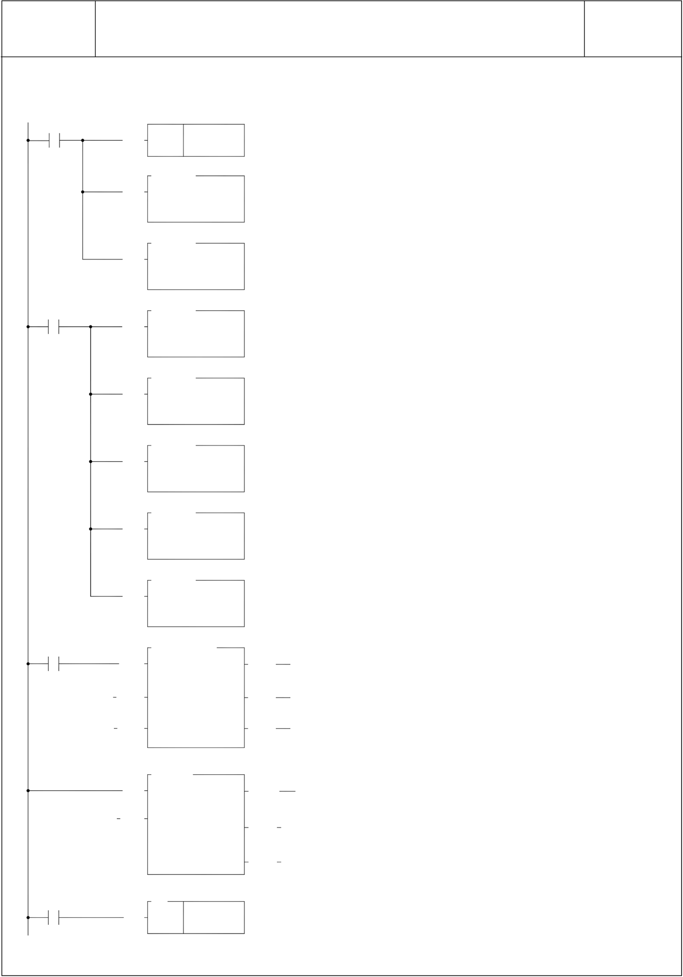
PLC station A sends data to PLC station B (PLC station B sends the received original data back to the PLC station A, loopback test), and checks whether the responding message of PLC station B is the same as its original data that had sent out; therefore, it can do simple test on software and hardware of PLC Port1 whether it is normal and error free. |
||||
FBs-PLC LINK
|
FUN151 CLINK M1924 |
Convenient Instruction of FUN151: MD1 |
FUN151 |
|||
|
(Which makes PLC act as the communication sender through Port 1~4) |
CLINK |
||||
|
EN |
RST |
R 108 |
• Clears the received data length to be 0 |
||
|
(for "transmit" only, this instruction is not required). |
|||||
|
M0 |
EN |
08.MOV |
ACT |
Y0 |
• Setting of the operation mode: |
||
|
S |
: 1 |
||||||
|
D |
: R 0 |
• Set to be "transmit then receive" mode (R0=1) |
|||||
|
EN |
08.MOV |
• Set the starting code (02H) and ending code (03H) for |
|||||
|
S |
: 0203H |
||||||
|
responding message in receiving. (without starting |
|||||||
|
D |
: R 1 |
||||||
|
and ending codes, R1=0 can also receive regularly) |
|||||||
|
08.MOV |
• Packing data to be transmitted: |
||||||
|
↑ |
EN |
S |
: 4 |
• Set the transmitting data length (R2=N). |
|||
|
M0 |
EN |
D |
: R 2 |
||||
|
• Fills in the data that is to be transmitted: |
|||||||
|
08.MOV |
|||||||
|
S |
: 2 |
||||||
|
• Fill in data 1 (R3= ‘ STX ‘ ) |
|||||||
|
D |
: R 3 |
||||||
|
EN |
08.MOV |
||||||
|
• Fill in data 2 (R4= ‘ O ‘ ) |
|||||||
|
S |
: 4FH |
||||||
|
D |
: R 4 |
||||||
|
• Fill in data 3 (R5= ‘ K ‘ ) |
|||||||
|
EN |
08.MOV |
||||||
|
S |
: 4BH |
||||||
|
D |
: R 5 |
||||||
|
• Fill in data 4 (R6= ‘ ETX ‘ ) |
|||||||
|
EN |
08.MOV |
||||||
|
S |
: 3 |
||||||
|
D |
: R 6 |
||||||
|
EN |
151P.CLINK |
||||||
|
Pt |
: 1 |
( ) |
|||||
|
M100 |
PAU |
MD |
: 1 |
ERR |
Y1 |
• When selecting "transmit then receive" mode, it |
|
|
SR: R0 |
( ) |
||||||
|
WR: R100 |
Y2 |
||||||
|
ABT |
DN |
||||||
|
( ) |
|||||||
|
17.CMP |
|||||||
|
M100 |
|||||||
|
EN |
a=b |
||||||
|
Sa |
: R 108 |
( ) |
|||||
|
employs the comparing instruction to judge whether |
|||||||
|
Sb |
: 0 |
||||||
|
U/S |
|||||||
|
a>b |
the responding message from the counter partner is |
||||||
|
received; if it is received, then M100=OFF, and it will |
|||||||
|
process the received data. |
|||||||
|
a<b |
|||||||
|
(For " transmit" mode, this program is not required) |
|||||||
|
66 |
|||||||
|
EN |
JMP |
1 |
|||||
FBs-PLC LINK
|
FUN151 |
Convenient Instruction of FUN151: MD1 |
FUN151 |
|
CLINK |
(Which makes PLC act as the communication sender through Port 1~4) |
CLINK |
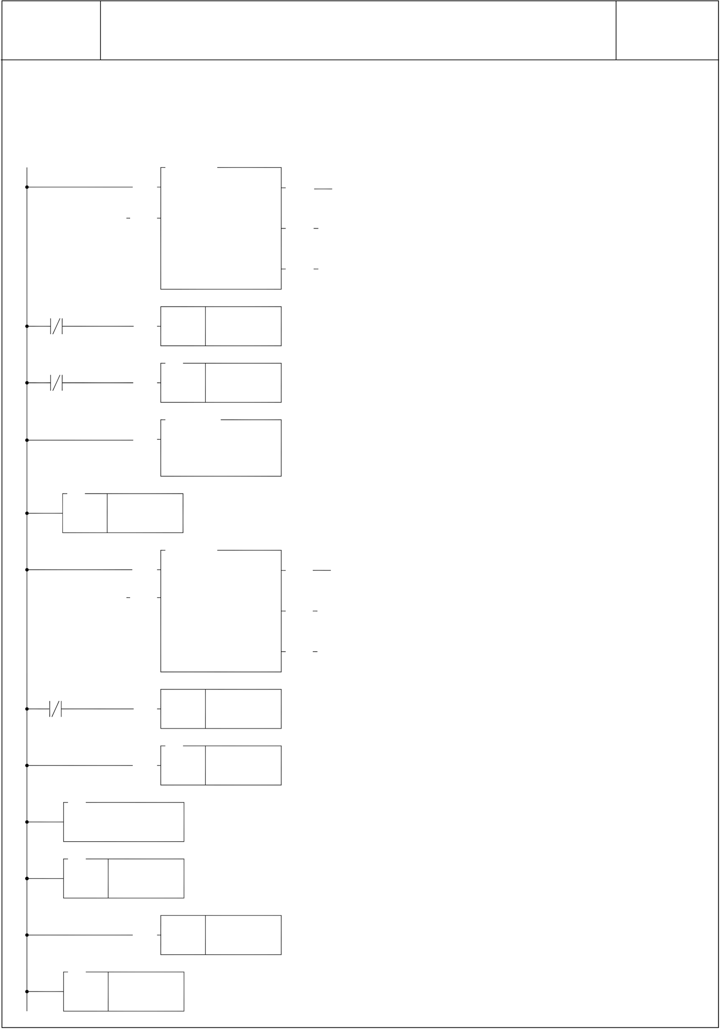
• The processing program for data received.
• For details of the data received, please refer to the explanation of following page.
|
EN |
17.CMP |
a=b |
M101 |
• Compares the received data length and transmitted |
|
|
Sa |
: R 108 |
( ) |
|||
|
U/S |
Sb |
: R 2 |
a>b |
||
|
data length. |
|||||
a<b
M101
|
M101 |
EN |
SET |
Y 3 |
• When the length is inconsistent, it sets up the error |
|
EN |
66 |
0 |
indication. |
|
|
JMP |
08.MOV
|
EN |
S |
: 0 |
• Clears the pointer V to be 0. |
|
D |
: V |
70
|
FOR |
R 2 |
17.CMP |
a=b |
M101 |
• Compares the consistency of all of the received data |
|
|
EN |
Sa |
: R 3V |
( ) |
|||
|
and transmitted data. |
||||||
|
U/S |
Sb |
: R 109V |
a>b |
|||
|
• Compares the received data and transmitted data |
||||||
one by one.
a<b
|
M101 |
EN |
SET |
Y 4 |
• When there is a data difference, set up the error |
indication.
15
|
EN |
(+1) |
V |
71
NEXT
65
LBL 0
• As the received data processed complete, clears the
|
65 |
EN |
RST |
R 108 |
received data length to be 0, and gets ready to receive |
|
1 |
||||
|
new data. |
||||
|
LBL |
FBs-PLC LINK
|
FUN151 CLINK |
Convenient Instruction of FUN151: MD1 |
FUN151 CLINK |
|||||||||||||||||
SR:Starting register of data transmission table
Note 1 : When selecting the transmit-only mode, the Starting /Ending code of receiving is meaningless. 2 : When it is in the "transmit then receive" mode, before the starting of transmission, it must first to estimate the starting and ending code of responding message from communication partner and write them into the receiving starting/ending code register (e.g. SR+1=0203H, 02H stands for starting code and 03H for ending code), so as to ensure the correct message frame receiving. The communication protocol with starting/ending code makes the identifying of every packet of messages easy, and the communication program is simple and efficient. 3 : When it is in the "transmit then receive" mode, fills the high byte of starting/ending code register with 0 if no starting code in responding message; if no ending code in responding message, fills 0 to the low byte of starting/ending code register. Adjusts the high byte of R4148 (message detection time interval) to judge whether a packet of data has been received completely; the unit is 0.001 second (the default is 0CH, 12mS). |
|||||||||||||||||||
FBs-PLC LINK
|
FUN151 CLINK |
Convenient Instruction of FUN151: MD1 |
FUN151 CLINK |
||||||||||||||||||||||||||||||||
|
The communication protocol without ending code depends on message detection time interval to tell whether it has received completely a packet of data (the setting of message detection time interval must be greater than the maximum response delay time between data bytes when communication partner is replying), thus it may ensure the receiving of the whole packet to be complete. Generally speaking, the data in transmitting is transmitted one byte after another continuously; therefore, if there is pause (greater than message detection time interval), it means the packet of message is transmitted completely. Explanation for the operand WR of FUN151:MD1
․
Result code : 0, transaction is successful. 2, data length error (the value is 0, or the packet of transaction is greater than 511) A, no response from the slave B, communication abnormal (received error data) ● Output Indicator :〝ACT〞 ON:Transaction is in progress 〝ERR〞 ON:Error occurred 〝DN〞 ON:One transaction finished |
||||||||||||||||||||||||||||||||||






FBs-PLC LINK
|
FUN151 CLINK |
Convenient Instruction of FUN151: MD2 |
FUN151 CLINK |
|||||||||||||||||||||||||||||||||||||||||||||||||||||||||||||||||||||||||||||||||||||||||||||||||||||||||||||||||||||||||||||||||||||||||
|
|||||||||||||||||||||||||||||||||||||||||||||||||||||||||||||||||||||||||||||||||||||||||||||||||||||||||||||||||||||||||||||||||||||||||||
|
Descriptions 1. FUN151 : MD2 instruction provides Fatek PLC with ability to receive message sent by peripherals with communication interface at any time. 2. The communication protocol is written with LADDER program, which must be consistent to the peripheral device. 3. When execution control 〝EN〞changes from 0→1 and both inputs “PAU” and “ABT” are 0, and if Port 1/2/3/4 hasn’t been controlled by other communication instructions [i.e. M1960 (Port1) 、 M1962 (Port2) 、 M1936 (Port3) 、 M1938 (Port4) = 1], this instruction will control the Port 1/2/3/4 immediately and set the M1960、 M1962、M1936、M1938 to be 0 (which means it is being occupied). If Port 1/2/3/4 has been controlled (M1960、M1962、M1936、M1938 = 0), then this instruction will enter into the standby status until the controlling communication instruction completes its transaction or pause/abort its operation to release the control right, and then this instruction will become enactive. 4. When the input “PAU” or “ABT” becomes 1, it gives up the receiving immediately (M1960、M1962、M1936、 M1938 = 1). 5. While it is in the receiving state, the output indication “ACT” is ON. 6. When a packet of data transaction finished (receive finished or receive then transmit completed), if there is error occurred, the output indication “DN” & “ERR” will be ON for one scan time. 7. When a packet of data transaction finished (receive finished or receive then transmit completed), if there is no error occurred, the output indication “DN” will be ON for one scan time. |
|||||||||||||||||||||||||||||||||||||||||||||||||||||||||||||||||||||||||||||||||||||||||||||||||||||||||||||||||||||||||||||||||||||||||||









FBs-PLC LINK
|
FUN151 CLINK |
Convenient Instruction of FUN151: MD2 |
FUN151 CLINK |
||||||||||||||||||||||||||
|
【Interface Signals】 Dedicated Relays and Registers for corresponding port :
1. Port Ready Indicator:This signal is generated from CPU. ON, it represents that port is free and ready. OFF, it represents that port is busy, data transaction is going. 2.Port Finished Indicator:This signal is generated from CPU. ON, it means data transaction has been completed. 3. Port Communication Parameters : 4.TX Delay & RX Time-out Span: The content of High Byte makes no sense at this mode. Note 1 : Once FUN151 : MD2 activated, it will stay in receiving state all the time; unless the input signal of PAU” or “ABT” becomes ON, then it will escape from receiving state and stop receiving and waiting for next time it will be activated again. 2 : When there is change on Starting/Ending code for receiving, it must make the input signal of PAU” or “ABT” becomes ON once, and re-activate the receive control “EN” from 0→1 to start message receiving |
||||||||||||||||||||||||||||
FBs-PLC LINK
|
FUN151 |
Convenient Instruction of FUN151: MD2 |
FUN151 |
|
CLINK |
(Which makes PLC act as the communication receiver through Port 1~4) |
CLINK |
Program example for loop back reply (This PLC station sends back the received data to the master, which
had sent out the data)
|
M1924 |
EN |
RST |
R 108 |
Clears the received data length to be 0. |
|
EN |
RST |
R 2 |
• Clears the transmitted data length to be 0. |
|
|
(for ”receive’ only, this program is not required). |
||||
|
EN |
08.MOV |
• Sets up the operation mode: |
||
|
S |
: 1 |
|||
|
EN |
D |
: R 0 |
• Sets “receive then transmit” mode. |
|
|
08.MOV |
||||
|
• Sets up the starting code (02H) and ending code |
||||
|
S |
: 0203H |
|||
|
(03H) (R1=0, it will receive regularly even without the |
||||
|
D |
: R 1 |
|||
starting and ending code)
|
M0 |
EN |
151P.CLINK |
ACT |
Y0 |
|
|
Pt |
: 1 |
||||
|
M2 |
PAU |
MD |
: 2 |
Y1 |
|
|
ERR |
|||||
|
SR |
: R0 |
||||
|
WR |
: R100 |
||||
|
Y2 |
|||||
|
↑ |
ABT |
DN |
|||
Y2
|
EN |
RST |
R 2 |
a=b |
M100 |
• When transmission complete, clears the transmitted |
|
|
EN |
17.CMP |
data length to be 0 (for "receive" only mode, this |
||||
|
Sa |
: R 108 |
instruction is not needed) |
||||
|
U/S |
Sb |
: 0 |
||||
|
a>b |
• While selecting "receive then transmit" mode, it employs |
|||||
the comparing instruction to tell whether a new packet of a<b message is received; if it is, the M100=OFF and it will process the received data.
|
M100 |
EN |
66 |
1 |
|
JMP |
103.BT_M
|
EN |
Ts |
: R 109 |
|
Td |
: R 3 |
|
|
L |
: R 108 |
• Copy all of the received data to responding registers.
|
EN |
08.MOV |
• R108 is the length of received data. |
||
|
S |
: R 108 |
|||
|
EN |
D |
: R 2 |
• After the received data processed, fills the received data |
|
|
RST |
R 108 |
|||
length to be the sending back data length to start the
|
65 |
1 |
responding transmission. |
|
LBL |
• Clears the received data length to be 0
(ready to receive new data).
FBs-PLC LINK
|
FUN151 CLINK |
Convenient Instruction of FUN151: MD2 |
FUN151 CLINK |
||||||||||||||||||||||||||
|
Explanation for the operand SR of FUN151: MD2 SR : Starting register of data reply table
Note 1 : When selecting the "receive only" mode, CPU fills the received data into the receiving registers and set the length after it has received a packet of message, and starts to receive the next packet of message immediately. 2 : When selecting the "receive then transmit" mode, CPU fills the received data into the receiving registers and set the length after it has received a packet of message; then it starts to wait for the reply data length which is not zero to start transmitting reply data (therefore when select this mode, it must control the reply data length to be zero before the reply data completely filled into the reply registers; when the reply data fills into the reply registers finished, it may then set the length of reply data). 3 : It must fills the starting code and ending code into the starting/ending code register before the starting of receiving (e.g. SR+1=0A0DH, 0AH stands for starting code and 0DH for ending code), so as to ensure it to be free from receiving error. The communication protocol with starting/ending code makes the identifying of every packet of messages easy, and the communication program is simple and efficient. 4 : If the receiving message without starting code, fills the high byte of starting/ending code with 0; if the receiving message without ending code, fills the low byte of starting/ending code with 0. Adjusting High Byte of R4148 (new message detection time interval) to detect whether a packet of message has been received completely, the unit is 0.001 second (default is 0CH, 12 mS). The communication protocol without ending code depends on new message detection time interval to tell whether it has received completely for a packet of data (the setting of new message detection time interval must be greater than the maximum delay time between data bytes to be received), thus it may ensure the receiving of the whole packet to be completed. Generally speaking, the data in transmitting is transmitted one byte after another continuously; therefore, if there is pause (greater than new message detection time interval), it means that the packet of message is transmitted completely. 5 : When selecting "receive only" mode, if the receiving message has no ending code, the interval between every packet of data sent by the sender must be greater than the receiver’s new message detection time interval, otherwise the receiver won’t be able to distinguish between each packet of data correctly. |
||||||||||||||||||||||||||||
FBs-PLC LINK
|
FUN151 CLINK |
Convenient Instruction of FUN151: MD2 |
FUN151 CLINK |
||||||||||||||||||||||||||||||||||||||
|
Explanation for the operand WR of FUN151:MD2
Note : When CPU received a packet of message, it filled the data to receiving registers and set up the received data length. Before the LADDER program starts to receive, you may clear the register of received data length to be 0; it means the receiving of a new packet of message when compared and found that the received data length is not zero. After the LADDER program gets the received data, it clears the received data length register to be 0. Just compare to see the received data length register is not zero means the receiving of a packet of new message, and so it may easily to process the receiving action. Result code : 0, data transaction is successful. 2, the data length is error (the value is 0, or the transaction is greater than 511) A, unable to reply message within Time-out span ("receive then transmit" mode). B, communication abnormal (received error data) Output indication : |
||||||||||||||||||||||||||||||||||||||||







FBs-PLC LINK
|
FUN151 CLINK |
Convenient Instruction of FUN151: MD3 |
FUN151 CLINK |
||||||||||||||||||||||||||||||||||||||||||||||||||||||||||||||||||||||||||||||||||||||||||||||||||||||||||||||||
MD : 3, serves as the master station of Fatek High
|
||||||||||||||||||||||||||||||||||||||||||||||||||||||||||||||||||||||||||||||||||||||||||||||||||||||||||||||||||
|
Descriptions 1. FUN151 : MD3, it provides high speed data sharing between Fatek’s PLC (data response time will not be influenced by the scan time of PLC). 2. A master PLC can link with 254 slave PLCs at the most to share data through the RS-485 interface. 3. FUN151 : MD3 is required only by master PLC, not by the slave PLC. 4. The station number of master PLC must be No.1, or it should be assigned by R4054 register if which is not No.1 but need to be as the master. 5. The setting of M1958 for slave PLC must be ON (M1958 OFF is for non-high speed link), but it’s not necessary for master PLC. 6. In high speed linking, the maximum Baud Rate is 921.6K bps and minimum is 38.4K bps (adjustable); the data bit is fixed at 8 Bits. Data is transmitted with binary code (which is twice time as fast as ASCII Code), and the error checking is adopting CRC-16, which is more reliable than Checksum. 7. The principle of high speed linking data transmission is based upon the COMMON DATA MEMORY concept to design; e.g. as the master PLC sent out the content of R0 to R31, .the contents of R0~R31 for all the slave PLCs will be the same as the master’s; when slave PLC no.2 sent out the contents of R32~R47, the R32~R47 contents of master PLC and other slave PLCs will be the same as PLC station no.2’s, etc. 8. When PLC is in STOP mode, the Port 2 enters into the standard interface mode that it can connect to WinProladder, MMI, or graphic supervisor (the communication parameter is set by R4158). 9. It employs the program coding or table filling method to plan for data flow control; i.e. for what kind of data being sent from which PLC station to all the PLC on line, it takes only 7 registers (5 of which is being physically used, and 2 reserved) to define; every 7 registers define once communication transaction. 10. When execution control “EN” changes from 0→1 and both pause “PAU” and abort “ABT” are 0, this instruction will control Port 2 and set M1962 to be “0” (being controlled) and processing the data transaction immediately, suppose the Port 2 is not controlled by other communication instruction (M1962=1). If Port 2 is being controlled (M1962=0), this instruction will enter into wait state until the controlling instruction completes the transmission or pause/abort the operation to release the control right (M1962=1); then it enacts from wait state, engages in the transmitting transaction and sets M1962 to be “0”. |
||||||||||||||||||||||||||||||||||||||||||||||||||||||||||||||||||||||||||||||||||||||||||||||||||||||||||||||||||








FBs-PLC LINK
|
FUN151 CLINK |
Convenient Instruction of FUN151: MD3 |
FUN151 CLINK |
|||||||||
|
11. When pause “PAU” or abort “ABT” of input is 1, it escapes from high speed data link immediately (M1962 ON). 12. Within the high speed linking, the output indication “ACT” is ON; Port 2 is occupied. 13.When there is error occurred while it is starting the high speed linking, the output indication “ERR” will be ON, and the high speed linking will not be performed.
M1958 : While in the PLC high speed data linking, slave PLC must set M1958 ON (not necessary for master PLC) M1962 : The signal is generated from CPU. M1963 : The signal is generated from CPU. When M1967 is ON (this signal is controlled by the user program) and after the last packet of communication transaction is completed, the CPU sets M1962 and M1963 ON, and the high speed data transmission will be stopped; it must control “ABT” (transmission abort) to be ON, and then restart execution control “EN↑” to change from 0→1 before the high speed linking can restart. When M1967 is OFF (this signal is controlled by the user program), the high speed data transmission will automatically restart a new transmission from the first packet of communication transaction (M1962 and M1963 is keeping OFF state) after the last packet of communication transaction is completed. M1967 : One-time or cycling control (controlled by the user program) OFF, successive cycles, it will restart from first packet of transaction when it has finished the last packet of transaction. R4054 : It assigns the PLC station which is not no.1 to act as the master of high speed linking.
When the station number of the PLC is not number 1, fills its station number (low byte of R4055 stores the station number) into the low byte of R4054 and writes to high byte of R4054 with 55H, and then controls the execution control input “EN↑” from 0→1; even though the PLC station which is not no.1, it can still be the master station for high speed linking. R4055 : When high byte of R4055 is not 55H,Low byte of R4055 shows the station number of PLC. When high byte of R4055 is 55H,Low byte of R4055 defines the station number of PLC. R4058 : Showing the station number of slave PLC which is abnormal while high speed linking (0: Represents normal; if many slave PLC were abnormal in the mean time, it is possible to see only one number; after the debugging of abnormal and clear R4058 to be 0 until the value of R4058 keeping to be 0, it will then network works normal). In communication transaction program or table, it must exist the case for slave station to send data to other stations then can the master PLC detect whether the slave station is online without error; if in the communication transaction program or table, there is only the master station sending data to slave stations, the master PLC can’t detect whether slave PLC is on line without error. The user must employ programming skill to add abnormal detecting program to the master PLC and |
|||||||||||
FBs-PLC LINK
|
FUN151 |
Convenient Instruction of FUN151: MD3 |
FUN151 |
|
CLINK |
( PLC serve as the master of “Fatek high speed CPU Link network” through Port2) |
CLINK |
slave PLC to do the error checking (as a matter of fact, the program is very simple; just makes the PLC, which is sending data, to create an ON↔OFF variation signal. Once the receiving PLC does not detect the ON↔OFF variation signal in a period of time, it means that there is communication error).
R4059 : Error logging of abnormal slave PLC while high speed linking.
|
R4059 |
High byte |
Low byte |
H |
|
Abnormal code |
Abnormal count |
Low byte : Abnormal count summation
High byte : Abnormal code
OAH, No response from slave station
OBH, Error data
01H, Framing Error
02H, Over Run Error
04H, Parity Error
08H, CRC error
Explanation for the checking method for abnormal communication is the same as that for R4058.
R4160 : Port 2 Rx/Tx Time-out setting (in high speed linking). The system will base on the setting of R4161 communication parameter to produce pertaining set point if high byte of R4160 is not 56H, the user need not to set it. If high byte of R4160 is 56H, the low byte of R4160 is reserved for manual setting.
R4161 : Communication parameter setting register for Port 2 High Speed CPU Link.
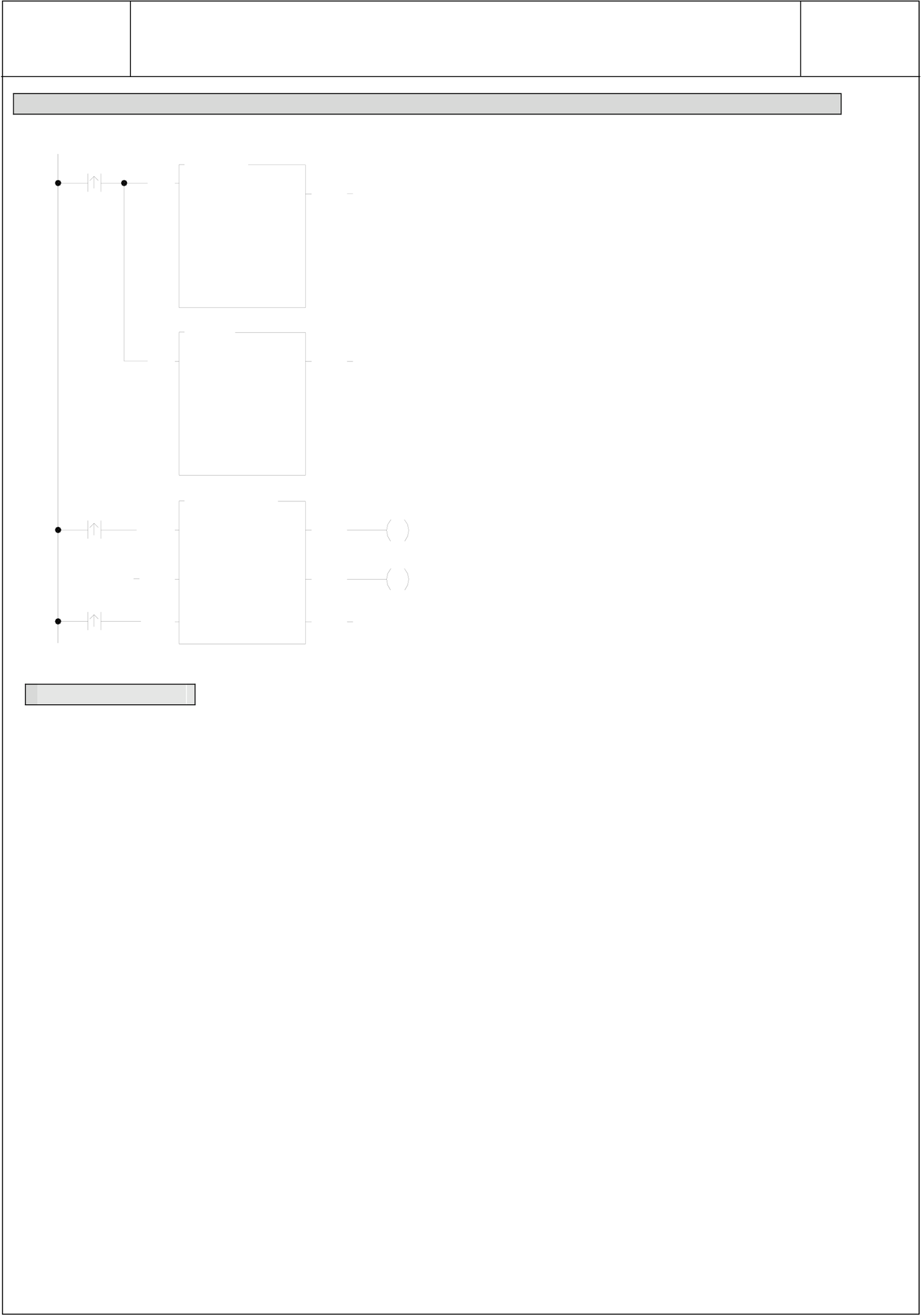
Program example 1 (PLC no. 1 serves as the master of high speed data linking)
|
M1963M1967 |
M100 |
• Planning R5000~R5199 to be ROR, the |
communication program will be stored together
|
M0 |
EN |
151P.CLINK |
ACT |
M1 |
with LADDER program. |
||
|
Pt : |
2 |
• When M1967 is ON, performs one cycle |
|||||
|
M100 |
PAU |
MD: |
3 |
ERR |
M2 |
transmission. It must start the abortion, then |
|
|
SR: |
R5000 |
||||||
|
restart M0 before it can perform high speed data |
|||||||
|
WR: |
R100 |
||||||
|
ABT |
DN |
link again. |
|||||
FBs-PLC LINK
|
FUN151 |
Convenient Instruction of FUN151: MD3 |
FUN151 |
|
CLINK |
( PLC serve as the master of “Fatek high speed CPU Link network” through Port2) |
CLINK |
Program example 2 (PLC which station number is not no.1 serves as the master of high speed data linking.)
|
M0 |
EN |
18.AND |
D=0 |
• Get PLC station number and write it into R4054 |
|
|
Sa : |
R4055 |
||||
|
Sb : |
00FFH |
||||
|
D : |
R4054 |
||||
19.OR
|
M0 |
EN |
Sa : |
R4055 |
D=0 |
M2 |
• Set the high byte for R4054 to be 55H |
|
|
Sb : |
5500H |
||||||
|
D : |
R4054 |
||||||
|
• Planning R5000~R5199 to be ROR, the |
|||||||
|
151P.CLINK |
|||||||
|
EN |
Pt : |
2 |
ACT |
M3 |
communication program will be stored together |
||
|
MD: |
3 |
with LADDER program. |
|||||
|
PAU |
ERR |
||||||
|
M1 |
|||||||
|
SR: |
R5000 |
||||||
|
• When ABT is not controlled, M1 instruction needs |
|||||||
|
WR: |
R100 |
||||||
|
ABT |
DN |
not to input. |
|||||
Program example 3
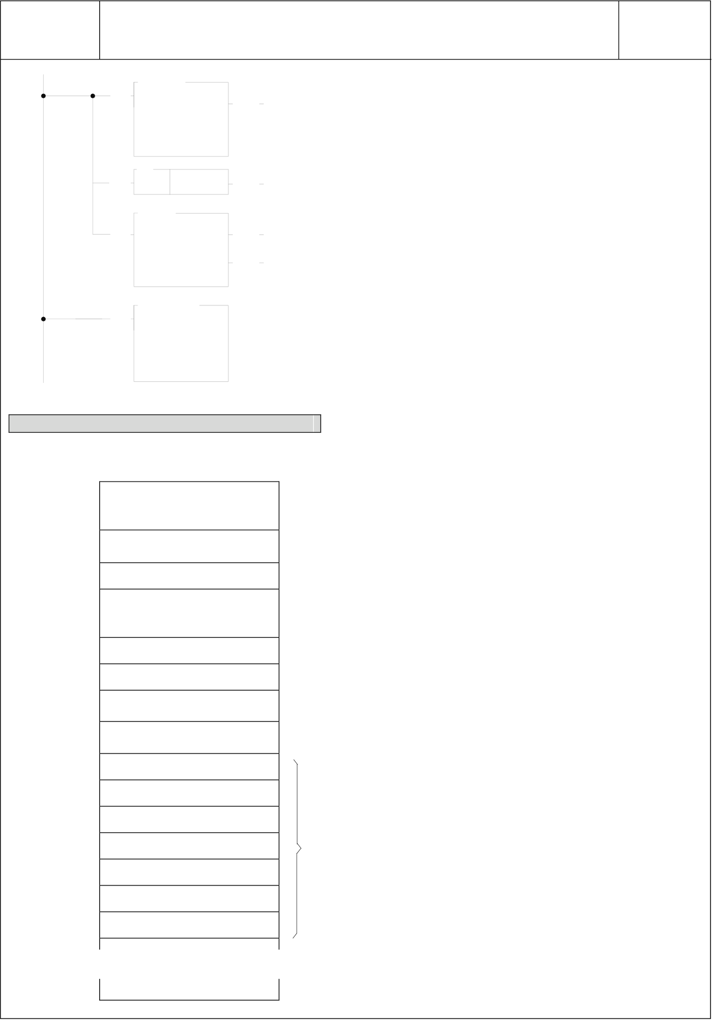
The same machine sets or equipments (with same LADDER program) perform multi-station data collection or distributed control through RS-485 high speed linking.
The principle for high speed data linking is based on COMMON DATA MEMORY concept to design; while designing, it must devise a successive data block and evenly distributed to respective PLCs to do data exchange among PLCs. e.g.:
R1000~R1031: The data block of PLC no. 1 (through high speed linking, the other PLCs’ content of R1000~R1031 become the same as that of PLC no.1).
R1032~R1063: The data block of PLC no. 2 (through high speed linking, the other PLCs’ content of R1032~R1063 become the same as that of PLC no.2).
• •
• •
• •
For example, get the production data (stored at R0~R31) from each machine set, and collectively gathering R1000~R1639 (suppose there are 20 sets linking) stored in master PLC through RS-485 high speed data linking; it needs merely the master PLC of high speed linking to connect to MMI or graphic supervisor, then it can monitor and store, for follow up processing, the production data of respective machine sets with real time effect.
Note : If it is simply for data collection and monitoring and no need to do real time control, employs the FUN151: MD0 can easily and concisely accomplish the assignment; when requiring real time control or supervisoring , it must employ FUN151: MD3 to accomplish a speedy, precisely controlling demand.
FBs-PLC LINK
|
FUN151 CLINK |
Convenient Instruction of FUN151: MD3 |
FUN151 |
||||
|
( PLC serve as the master of “Fatek high speed CPU Link network” through Port2) |
CLINK |
|||||
|
EN |
18.AND |
D=0 |
•Get PLC station number and write it in pointer Z |
|||
|
Sa : |
R4055 |
|||||
|
Sb : |
00FFH |
|||||
|
D : |
Z |
|||||
|
EN |
16 |
Z |
UDF |
•Station number deducts 1 |
||
|
(-1) |
||||||
|
13.(*) |
||||||
|
EN |
Sa : |
R 2000 |
D=0 |
•R2000 = Length of data to be sent from each station (e.g. 32) |
||
|
Sb : |
Z |
D<0 |
•data length * (station number−1): |
|||
|
Directing to the apportioned data block of this station. |
||||||
|
D : |
Z |
|||||
|
EN |
103.BT_M |
•Move production data from respective stations to the |
||||
|
Ts : |
R 0 |
apportioned data block of respective stations, and |
||||
|
Td : |
R 1000Z |
|||||
|
transmitting it to all other PLCs on line through high speed |
||||||
|
D : |
R 2000 |
|||||
|
data linking. |
||||||
Explanation for operand SR of FUN151: MD3
SR:Starting register for communication program of CLINK instruction
|
SR+0 |
Packets of data |
•Low Byte is valid. A packet of transmission demands 7 registers |
|
|
transaction |
to describe; i.e. 7 registers define a packet of data. |
||
|
SR+1 |
Station number to transmit |
||
|
•Low Byte is valid. 1~254 |
|||
|
Command code |
|||
|
SR+2 |
•Low Byte is valid, it can only be 4 (high speed linking command). |
||
|
SR+3 |
Length of this packet of |
• Low Byte is valid. 1~32, defines the data length of one |
|
|
data |
transaction. |
||
|
SR+4 |
Data type |
• Low Byte is valid. 12=R; 13=D. |
|
|
SR+5 |
Data starting reference |
•Word is valid. Defines starting number of working data. |
|
|
SR+6 |
Reserved |
•Code for data type |
Data starting reference |
|
SR+7 |
Reserved |
12: R data register |
0~3839 |
|
13: D data register |
0~3999 |
||
|
SR+8 |
Station number to transmit |
Describing for the 2_nd packet of transaction |
|
|
SR+9 |
04 |
||
|
‧ |
Length of data |
||
|
‧ |
Data type |
||
|
‧ |
Data starting reference |
||
|
‧ |
Reserved |
||
|
‧ |
Reserved |
||
FBs-PLC LINK
|
FUN151 CLINK |
Convenient Instruction of FUN151: MD3 |
FUN151 CLINK |
|||||||||||||||||||||||||||||||||||
Result code : 0 : Correct format ● For easy programming and trouble shooting, the WinProladder provides the table editing environment to edit the communication table of FUN151 instruction; Key in the complete FUN151 instruction first and then move the cursor to the position of it, depressing the "Z" key, now comes the table editing environment. The user can create the new communication table or display the existed table under this friendly user interface operation.
※ Only Port 2 is valid for FUN151:MD 3
|
|||||||||||||||||||||||||||||||||||||
FBs-PLC LINK
|
FUN151 |
CPU Link by Way of Port 1 to Connect to Modem |
FUN151 |
|
CLINK |
CLINK |
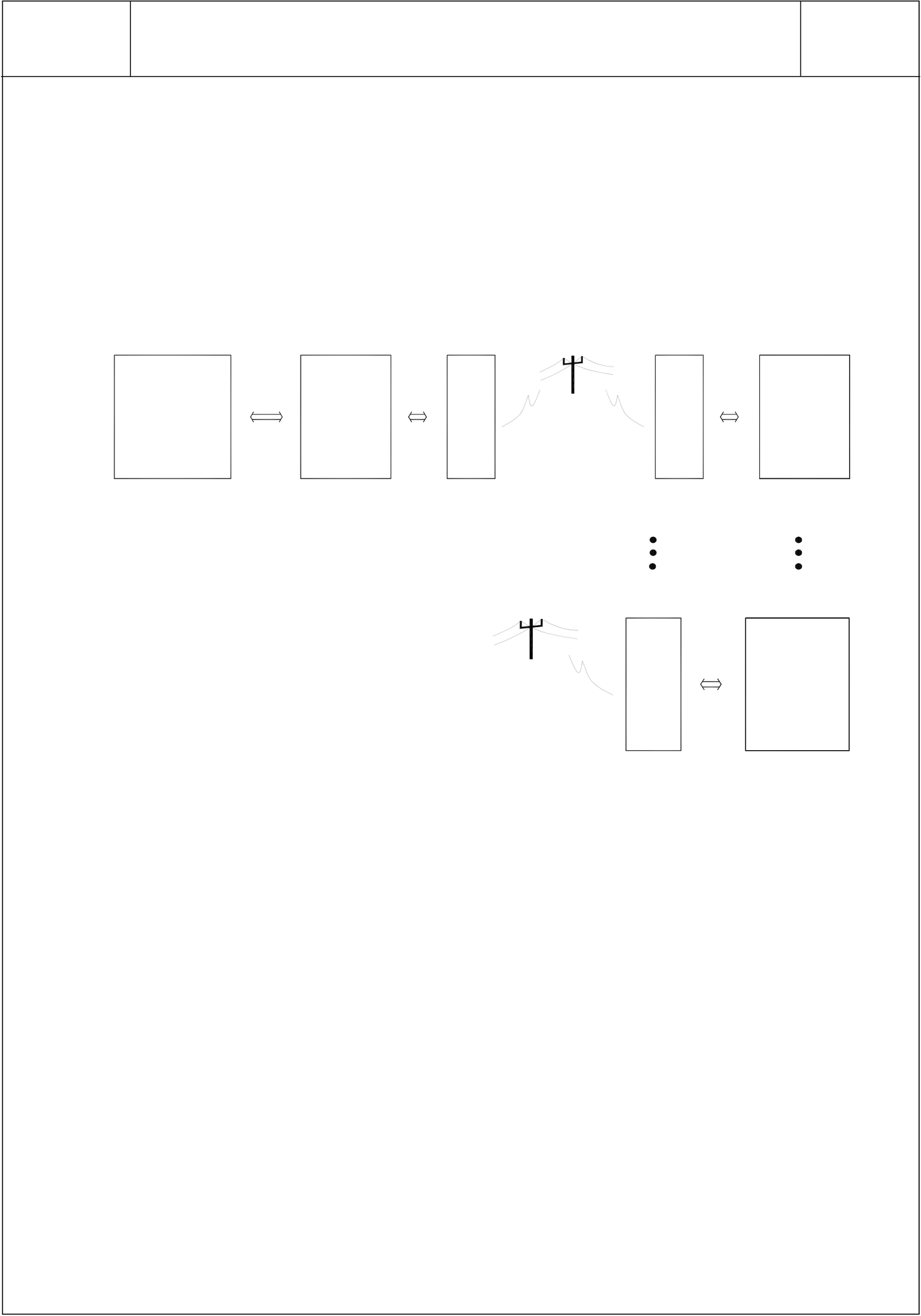
● PLC can connect to MODEM through communication port 1, and by way of telecommunication network to link and share data with remote PLC. Its application is as follows :
.Perform automatic data collection from the remote end.
.Automatically report for alarm and abnormal conditions.
.Associate with current available graphic supervisor software or MMI etc. standard products to constitute a wide area network automatic monitoring system. It doesn’t need to develop specific designing, so as to reduce the development risk and time limit.
● Hardware configuration, and setting :
|
SCADA |
(Data collection PLC) |
M |
M |
(Data reply PLC) |
|
or |
FBS-PLC |
O |
O |
FBS-PLC |
|
MMI |
D |
D |
||
|
or |
E |
E |
||
|
M |
M |
|||
|
WinProladder |
Data collecting PLC :
.Don’t need to store phone number within the CPU
.High Byte of R4149 = 55H (MODEM function) Data reply PLC :
(Data reply PLC)
|
.High Byte of R4149 = 55H (MODEM function) |
M |
FBS-PLC |
|
.R4140~R4145 sets the phone number for general data |
O |
|
|
collecting PLC end (extension phone function allowed). |
D |
|
|
E |
||
|
e.g. Phone number is 02-28082192, then |
M |
R4140=8220H, R4141=1280H, and R4142=0E29H.
If phone number is : 02-28082192 ext 100, then R4140=2A20H, R4141=2808H, R4142=A291H, R4143=AAAAH, R4144=001AH, R4145=000EH.
.Explanation: R4140~R4145 is telephone number register for dialing;
“E” is the ending character of phone number; “A” is the dial delaying character (usually the dialing of extension number or international long distance call can be reached by making use of dial delaying, the delayed time for a delaying character is based on MODEM setting, which is about 2 second). “B” stands for “#” character, and “C” stands for “*” character.
.It employs CLINK (FUN151:MD0) instruction to write data to the general data collecting PLC or to read data from general data collecting PLC (refer to FUN151:MD0 Instruction user guide).
*** The maximum communication Baud Rate can reach 115200 bps (both of the communication ends must be consistent in setting)
.Let the communication parameters be 8-bit and Non-parity will be better for almost Modem
FBs-PLC LINK
|
FUN151 |
CPU Link by Way of Port 1 to Connect to Modem |
FUN151 |
|
CLINK |
CLINK |
.The wiring of PLC communication port1 and MODEM:
Fatek PLC (DB-9) MODEM (DB-25)
|
PIN 3:RXD ←──────────→PIN 2:TXD ←──────────→PIN 8:RTS ←──────────→PIN 7:CTS ←──────────→ |
TXD |
(PIN_3) |
|
|
RXD (PIN_2) |
|||
|
CTS |
(PIN_4) |
||
|
RTS |
(PIN_5) |
||
|
PIN 5:SG |
←──────────→ |
SG |
(PIN_7) |
|
┌── |
DSR (PIN_6) |
||
MODEM dialing interface signal
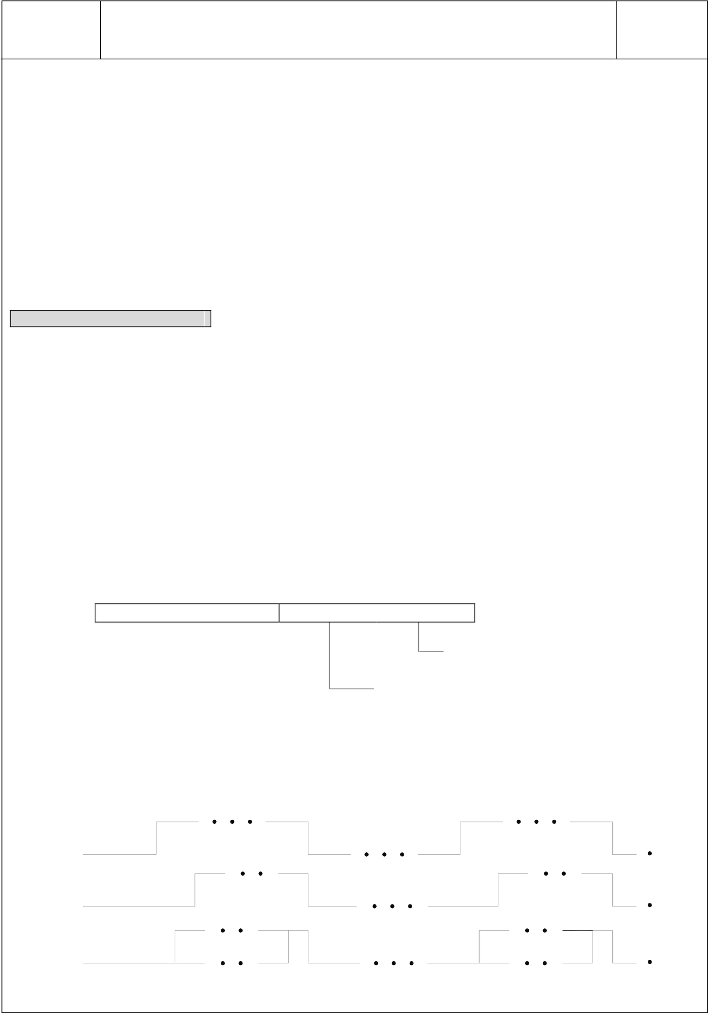
M1959 : OFF, dialing by “Tone” ;
ON, dialing by “Pulse”
M1964 : OFF→ON, dial up ;
ON→OFF, hang up
R4163 : The Low Byte of R4163 is used to control the application of X instruction while MODEM dialing. =1, it does not detect dial tone nor busy tone while MODEM dialing.
=2, it detects only dial tone but does not detect busy tone while MODEM dialing.
=3, it dials directly without detecting dial tone, but will detect busy tone after MODEM dialing.
=4, it detects both dial tone and busy tone for MODEM dialing.
For other values, it works as 4; different country system needs to adjust the setting pertaining to the country.
b15 b8 b7 b4 b3 b0
|
R4163 |
High Byte |
Low |
Byte |
H |
b0~b3
B7~b4=0,AT&F……as default setting
B7~b4=1,AT&Y……as User Profile setting
The High Byte of R4163 is used to set the ring count for auto answer mode of Modem.
|
M1964 |
Dial up |
Hang up |
Dial up |
Hang up |
|
(LADDER) |
M1965
|
(CPU) |
Connect |
Connect |
|
M1966 |
Disconnect |
Disconnect |
|
(CPU) |
FBs-PLC LINK
|
FUN151 |
CPU Link by Way of Port 1 to Connect to Modem |
FUN151 |
|
CLINK |
CLINK |
Note 1 : Of M1965 and M1966, there will be only one ON, not both to be ON at the same time.
2 : The waiting time for dial connection is 1 minute; if unable to connect, it will redial twice (totally 3 times). If all of the dial connection tries failed, CPU will set M1966 to be ON (connection failed).
3 : When the quality of communication is not stable and easy to disconnect, you may employ the abnormal detecting function of CLINK instruction to control M1964 redials for connection (delay time of redial must be more than 10 seconds).
4 : When PLC change from RUN to STOP, the CPU will automatically change MODEM to be receiving state, which could accept the remote side dial connection.
5 : When PLC is not in dialing or MODEM connection states, CPU will automatically change MODEM to be receiving state, which could accept the remote side dial connection.
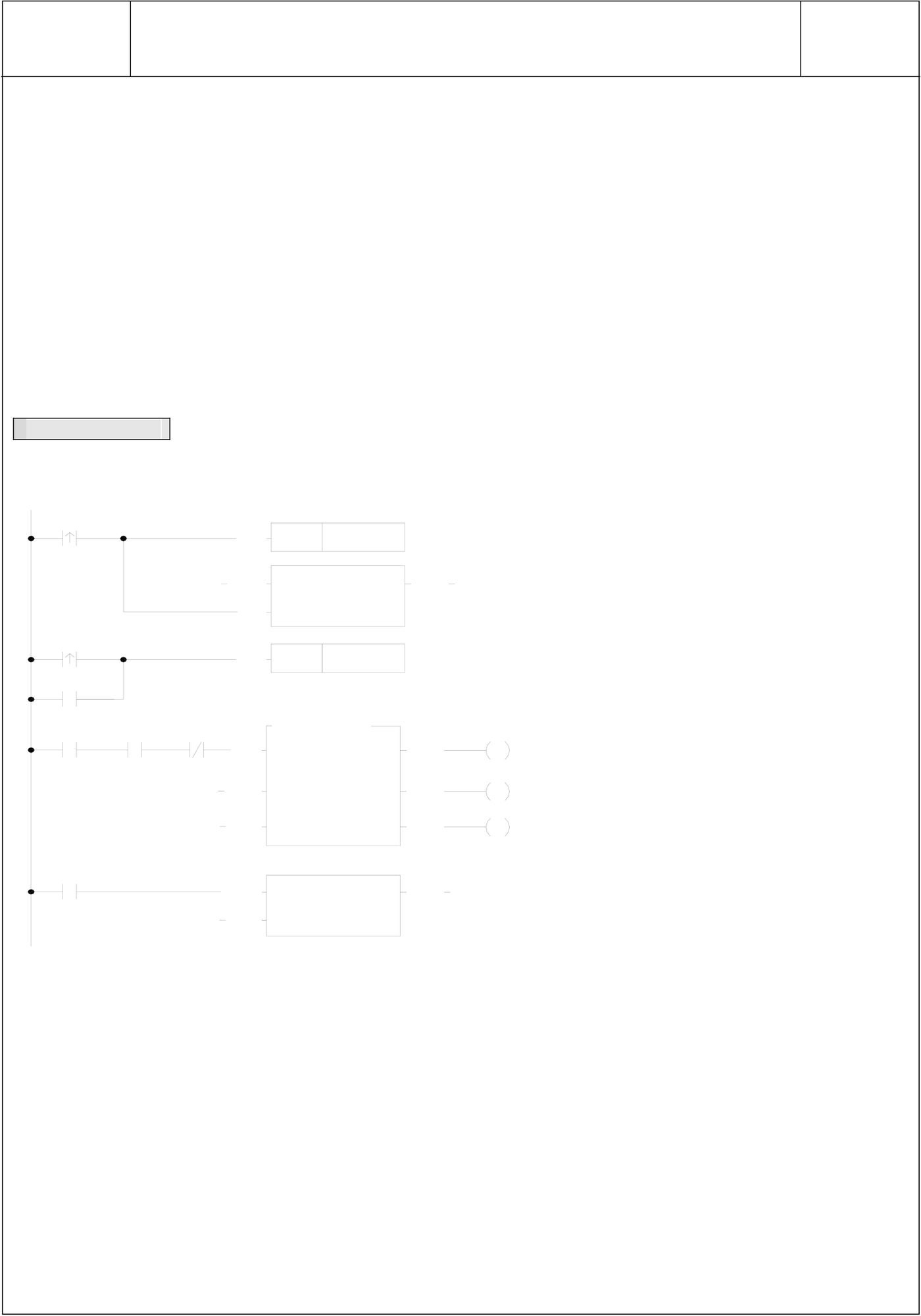
Program example
|
M 0 |
M 1965 |
C 0 |
E N |
S E T |
M 1964 |
C U P |
M 100 |
● When M0 changes from 0→1, dials up. |
|
|
● Clears the transaction count. |
|||||||||
|
P LS |
C 0 |
||||||||
|
C 0 |
E N |
P V : |
3 |
A C T |
● Hang up after transactions completed |
||||
|
E N |
R S T |
M 1964 |
|||||||
|
or connection failed. |
|||||||||
|
M 1966 |
|||||||||
|
151P .C LIN K |
|||||||||
|
E N |
● Planning R5000~R5199 to be ROR, |
||||||||
|
M 1960 |
|||||||||
|
P t : |
1 |
||||||||
|
M 1961 |
P A U |
M D : |
0 |
E R R |
M 101 |
the communication program will be |
|||
|
S R : |
R 5000 |
||||||||
|
stored together with LADDER |
|||||||||
|
M 102 |
|||||||||
|
W R : |
R 100 |
||||||||
|
A B T |
D N |
||||||||
|
program. |
|||||||||
|
P LS |
C 0 |
C U P |
● Counting after all transactions |
||||||
|
C LR |
P V : |
3 |
completed |
||||||
|
13.2 Application for FUN150( Modbus) Instruction |
|
13.2.1 Procedures for Usage |
Start
Hardware wiring to connect the various
stations (PLC, ASCII peripherals, etc.)
Set up the station number of the linking stations and make a consistent
● Station number can be set to any one between 1 to 254
communication parameters setting for without replication.
these stations.。
Fill in the value to the communication interface register (Rxxxx) of FUN150
● For communication parameters, please refer to the description of "Communication Related Setting".
(Modbus) if necessary; properly adjust the
Time_out timer to detect communication
error, transaction delay to meet slow
response device , etc.
Write FUN150 instruction to PLC, which
serves as the master station or performs
communication sender/ receiver, and then
fill the communication program into the
register table assigned by operand SR.
FUN150 will then automatically send or
receive data according to the definition of
communication program. The user can
easily reach the various function services
of Modbus by accessing the table like
of communication program.
End
13.2.2 Explanation Application Program for FUN150
This section will instruction to explain FUN150(Modbus) usages, with respective practical application program
examples.








FBs-PLC LINK
|
FUN150 M-BUS |
Convenient Instruction for Modbus RTU/ASCII Master |
FUN150 M-BUS |
|||||||||||||||||||||||||||||||||||||||||||||||||||||||||||||||||||||||||||||||||||||||||||||||||||
|
|||||||||||||||||||||||||||||||||||||||||||||||||||||||||||||||||||||||||||||||||||||||||||||||||||||
|
Descriptions
easy to communicate with the intelligent peripheral with Modbus RTU/ASCII protocol. 2. The master PLC may connect with 247 slave stations through the RS485 interface. 3. Only the master PLC needs to use M-BUS instruction. 4. It employs the program coding method or table filling method to plan for the data flow controls; i.e. from which one of the slave station to get which type of data and save them to the master PLC, or from the master PLC to write which type of data to the assigned slave station. It needs only seven registries to make definition; every seven registers define one packet of data transaction. 5. When execution control 〝EN〞changes from 0→1 and the input “ABT” is 0, and if Port 1/2/3/4 hasn’t been controlled by other communication instructions [i.e. M1960 (Port1)、 M1962 (Port2) 、 M1936 (Port3) 、 M1938 (Port4) = 1], this instruction will control the Port 1/2/3/4 immediately and set the M1960、M1962、 M1936、M1938 to be 0 (which means it is being occupied), then going on a packet of data transaction immediately. If Port 1/2/3/4 has been controlled (M1960、M1962、M1936、M1938 = 0), then this instruction will enter into the standby status until the controlling communication instruction completes its transaction or pause/abort its operation to release the control right (M1960、M1962、M1936、M1938 =1), and then this instruction will become enactive, set M1960、M1962、M1936、M1938 to be 0, and going on the data transaction immediately. 6. While in transaction processing, if operation control “ABT” becomes 1, this instruction will abort this transaction immediately and release the control right (M1960、M1962、M1936、M1938 = 1). Next time, when this instruction takes over the transmission right again, it will restart from the first packet of data transaction. 7. While〝A/R〞=0,Modbus RTU protocol;〝A/R〞=1,Modbus ASCII protocol。 8. While it is in the data transaction, the output indication “ACT” will be ON. 9. If there is error occurred when it finishes a packet of data transaction, the output indication “DN” & “ERR” will be ON. 10. If there is no error occurred when it finishes a packet of data transaction, the output indication “DN” will be ON. Note : Modbus ASCII Mode has been supported after OS Version 4.24 and later |
|||||||||||||||||||||||||||||||||||||||||||||||||||||||||||||||||||||||||||||||||||||||||||||||||||||













FBs-PLC LINK
|
FUN150 M-BUS |
Convenient Instruction for Modbus RTU/ASCII Master |
FUN150 M-BUS |
|||||||||||||||||||||||||||||||||||||||
|
【Interface Signals】 Dedicated Relays and Registers for corresponding port :
1. Port Ready Indicator:This signal is generated from CPU. ON, it represents that port is free and ready. OFF, it represents that port is busy, data transaction is going. 2. Port Finished Indicator : This signal is generated from CPU. When the communication program completed the last packet of data transaction, this signal will be ON for one scan time (for successive data transaction). When the communication program completed the last packet of data transaction, this signal will be still ON (for single packet of data transmission) 3. Port Communication Parameters : 4. TX Delay & RX Time-out Span : When the master PLC sent out the read/write command to the slave station, the slave station didn’t reply within this period means that there is abnormal event in communication called Time-out. When there are multi-drop linking, properly adjust this value (greater than 1 scan time of the slave station with the longest scan time) to shorten the communication response time among the active linking stations if there are many slave stations power off (The time-out cases will happen). The content of High Byte defines the transmission delay time between two packets of data transaction for M-BUS instruction; its unit is 0.01 second (the default is 0). For point to point link, this value can be set as 0 to shorten the communication transaction time and promote the communication efficiency. In the case of linking multi-drop and if the scan time of master PLC is far longer than any slave station, this value can also be set to 0 to shorten the communication transaction time and promote the communication efficiency. When there are multi-drops linking and the scan time of master PLC is close to that of slave station’s, it must properly adjust this value (greater than 1 scan time of the slave station with the longest scan time) to reach the best, error-free communication quality |
|||||||||||||||||||||||||||||||||||||||||

FBs-PLC LINK
|
FUN150 |
Convenient Instruction for Modbus RTU/ASCII Master |
FUN150 |
|
M-BUS |
(Which makes PLC as the Modbus RTU/ASCII master through Port 1~4) |
M-BUS |
5. Setting of RX Time-out Span: Please refer this chapter, page 13-4~13-5 for details
6. Edge Trigger Execution:Please refer this chapter, page 13-5~13-6 for details
※When receiving message without ending code, and if M1956=1, then R4148 high byte of the received Time-out span setting is used to determine whether a data have been received or not, the unit is 0.001 second (default is 0CH, 12mS).
Program example (Automatic cycling transmission)
|
M 1 |
M 1 9 6 0 |
E N |
1 5 0 P .M _ B U S |
A C T |
M 1 0 |
•Configure R5000~R5399 as the read only |
|
|
P t : |
1 |
M 1 1 |
register (ROR) before programming, after |
||||
|
S R : |
R 5 0 0 0 |
||||||
|
A /R |
WR : |
D 0 |
E R R |
M 1 2 |
then, when storing program, the ladder |
||
|
A B T |
D N |
program will automatically contains the |
|||||
communication program .
|
M 1 1 |
E N |
0 8 D .M O V |
•When there is communication error, gets |
||
|
S : |
D 0 |
||||
|
and stores the error message to D1000 & |
|||||
|
D : |
D 1 0 0 0 |
||||
D1001 would be helpful for error analysis
|
M 2 |
M 1 9 6 2 |
E N |
1 5 0 P .M _ B U S |
A C T |
M 2 0 |
or logging. |
|
|
P t : |
2 |
||||||
|
A /R |
S R : |
R 5 2 0 0 |
E R R |
M 2 1 |
|||
|
WR : |
D 2 0 |
||||||
M 2 2
|
M 2 1 |
A B T |
0 8 D .M O V |
D N |
||
|
E N |
S : |
D 2 0 |
|||
|
D : |
D 1 0 0 2 |
||||
FBs-PLC LINK
|
FUN150 M-BUS |
Convenient Instruction for Modbus RTU/ASCII Master |
FUN150 M-BUS |
||||||||||||||||
|
Explanation on program example 1. When execution control 〝EN〞changes from 0→1, and Port 1 is not occupied by other communication instruction (M1960 ON), M-BUS instruction will start the data transaction. The M1960 is OFF during data transaction, and when the transaction is finished, the M1960 becomes ON. Employ the OFF←→ON change of M1960 (M-BUS execution control “EN” = 0→1 means starting) may automatically starts for every packet of data transaction successively (when the last packet of transaction is completed, it will automatically return to the first packet of transaction to obtain the automatic cycling transmission). 2. When execution control 〝EN〞changes from 0→1, and Port 2 is not occupied by other communication instruction (M1962 ON), M-BUS instruction will start the data transaction. The M1962 is OFF during data transaction, and when the transaction is finished, the M1962 becomes ON. Employ the OFF←→ON change of M1962 (M-BUS execution control “EN” = 0→1 means starting) may automatically starts for every packet of data transaction successively (when the last packet of transaction is completed, it will automatically return to the first packet of transaction to obtain the automatic cycling transmission).
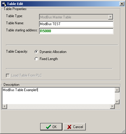
Click the “Modbus Master” Item which in project windows :
Table Edit Modbus Master Æ Click right button and select “Add Modbus Master Table”
|
||||||||||||||||||
FBs-PLC LINK
|
FUN150 M-BUS |
Convenient Instruction for Modbus RTU/ASCII Master |
FUN150 M-BUS |
|
● Table Type : It will be fixed to ” Modbus Master Table ”. ● Table Name : For modify or debug, you can give a convenient name. ● Table Starting address : Enter the address which Starting register of communication Table
|
||


FBs-PLC LINK
|
FUN150 M-BUS |
Convenient Instruction for Modbus RTU/ASCII Master |
FUN150 M-BUS |
|||||||||||||||||||||||||||||||||||||||||||||||||||||||||||||||||||||||||
|
Starting register for communication program of M-BUS instruction SR:Starting register for communication program of M-BUS instruction
•Low Byte is valid ; =1, means "Read data from slave station"
=3, means "Write single data to slave station"
•
|
|||||||||||||||||||||||||||||||||||||||||||||||||||||||||||||||||||||||||||




FBs-PLC LINK
|
FUN150 M-BUS |
Convenient Instruction for Modbus RTU/ASCII Master |
FUN150 M-BUS |
||||||||||||||||||||||||||||||||||||||||||||||||||||||
|
zData code, type and reference number of Master station (FATEK PLC)
zData code, type and reference number of Slavestation (Modbus slave)
z WR:Starting register for instruction operation of M-BUS (FUN150)
Result code : 0, Transaction is successful. 2, Data length error (for length is 0 or over limit). 3, Command code error (Command code is0 or greater than 3) 7, Port error(Not Port 1~4) |
||||||||||||||||||||||||||||||||||||||||||||||||||||||||
FBs-PLC LINK
|
FUN150 M-BUS |
Convenient Instruction for Modbus RTU/ASCII Master |
FUN150 M-BUS |
||||||||||||||||||||||
|
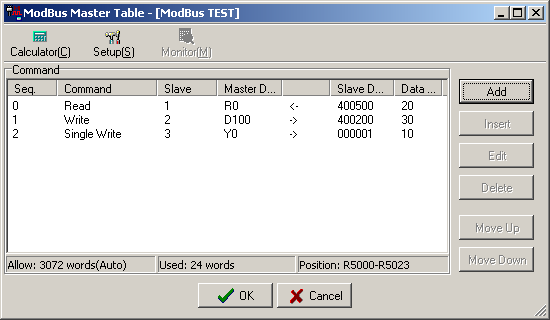
A, No response from slave station (Time-out error). B, Communication error (received error data or exception reply ). ● For easy programming and trouble shooting, the WinProladder provides the table editing environment to edit the communication table of FUN150 instruction; Key in the complete FUN150 instruction first and then move the cursor to the position of it, depressing the "Z" key, now comes the table editing environment. The user can create the new communication table or display the existed table under this friendly user interface operation.
Sequence No.CommandSlaveData of MasterData of SlaveData length
M0~M1911 ← 000001~065535 1~255 S0~S999 ← 000001~065535 1~255 Y0~Y255 ← 100001~165535 1~255 M0~M1911 ← 100001~165535 1~255 S0~S999 ← 100001~165535 1~255 R0~R3839 ← 400001~465535 1~125 D0~D3999 ← 400001~465535 1~125 R0~R3839 ← 300001~365535 1~125 D0~D3999 ← 300001~365535 1~125
M0~M1911 → 000001~065535 1~255 S0~S999 → 000001~065535 1~255 R0~R3839 → 400001~465535 1~125 D0~D3999 → 400001~465535 1~125 2 . |
||||||||||||||||||||||||
FBs-PLC LINK
|
Modbus Slave |
Address mapping between Modbus and Fatek |
Modbus Slave |
||||||||||||||||||||||||||||||||||||||||||||||||||||||
|
●FBs-PLC can use FUN150 to be Modbus protocol Master, besides it also can be Modbus communication Slave by configuration(Port1~Port4, but Port0 fixed to Fatek communication protocol) then it can connect with the intelligent peripheral. ● See below for Modbus and Fatek data address mapping rules: Mapping Rule
|
||||||||||||||||||||||||||||||||||||||||||||||||||||||||
FBs-PLC LINK
|
Modbus Slave |
Address mapping between Modbus and Fatek |
Modbus Slave |
||||||||||||||||||||||||||||||||||||||||||||||||||||||||||||||||
|
||||||||||||||||||||||||||||||||||||||||||||||||||||||||||||||||||
FBs-PLC LINK
|
Modbus Slave |
Port 1~4 simulates the Modbus slave device |
Modbus Slave |
||||||||||||||||||||||||||||||||
|
Add new address mapping for Modbus slave communication protocol; out of range access, the PLC will reply communication error
|
||||||||||||||||||||||||||||||||||
FBs-PLC LINK
|
Modbus Slave |
Port 1~4 simulates the Modbus slave device |
Modbus Slave |
||||||||||||
For example. R3968=A55AH, it means new address mapping for Modbus slave comm. protocol R3969=0, R3970=1000, R3971=100: Mapping 000001 ~ 000100 (Modbus) |
||||||||||||||
FBs-PLC LINK
|
Modbus Slave |
Configuration of Port 1~4 for working as the Modbus Protocol |
Modbus Slave |
|||||||||
|
● Port 1~4 support Modbus RTU/ASCII (Slave) communication protocol ﹒Method 1 (All OS versions of FBs PLC can support this method) R4047 : Upper Byte = 55H,configure the communication port of Modbus RTU protocol = Other values,Port 1~4 don’t support Modbus RTU protocol (FATEK as the default) Lower Byte : Port assignment for Modbus RTU protocol Format as below : Upper Byte Lower Byte
b0, Reserved ; b1=0, Port 1 acts as FATEK protocol b2=0, Port 2 acts as FATEK protocol b3=0, Port 3 acts as FATEK protocol b4=0, Port 4 acts as FATEK protocol . . b7~b5, Reserved ※ It allows to assign multiple ports for Modbus RTU protocol,where the corresponding bit must be 1。 For example: |
|||||||||||
FBs-PLC LINK
|
Modbus Slave |
Configuration of Port 1~4 for working as the Modbus Protocol |
Modbus Slave |
||||||||||||||||||||||||||||||||||||||||
|
﹒Method 2 (FBs PLC OS V4.24 or later can support this method) Format as below : Upper Byte Lower Byte
|
||||||||||||||||||||||||||||||||||||||||||
Tip: press ← → to switch chapters, Ctrl+K to search