A real time clock (RTC) has been provided in the M-Series main unit, in the form of being built-in or expanded. Whether the power is on or not, the RTC always keeps accurate time. It provides 7 kinds of time value data-week, year, month, day, hour, minute and second. Users can take advantage of the real time clock to do 24 hours controls throughout the year (for example, businesses or factories can switch lights on and off at set times each day, control gate access, and do pre-cooling and pre-heating before business or operations begin). It can enable your control system to automatically coordinate with the schedule of the operation, and not only does it lift the level of automatic control up a notch, it also improves efficiency.
3-1 Calendar Time of System
3-1-1 RTC Register
Within PLC, there are special purpose registers (RTCR) for storing the time values of the RTC. There are 8 RTCR registers in all, going from R35312 to R35319. R35312 to R35318 are used to store the 7 kinds of time values mentioned above, from weeks to seconds. Because in practical daily application, certain hour and minute time data is often used, we have specially merged the time values of the hour register (R35314) and minute register (R35313) within RTCR, and put them in R35319 high byte and low byte, so they can be accessed by the user. The detail is shown in the table.
|
Register |
Description |
|---|---|
|
R35312 |
Second |
|
R35313 |
Minute |
|
R35314 |
Hour |
|
R35315 |
Day |
|
R35316 |
Month |
|
R35317 |
Year |
|
R35318 |
Week |
|
R35319 |
Hour (High byte) + Minute (Low byte) |
Table 3 RTC of System and the Corresponding Register
This figure shows the relationship between RTC and registers R35312~R35318, and the related control switches and status flags (M9179~M9182) when RTC is accessed.
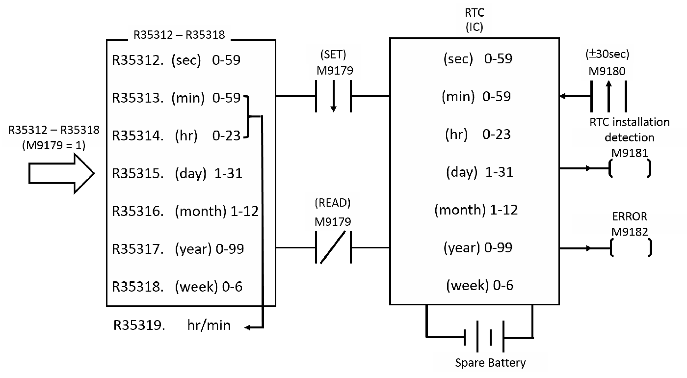
Figure 1 RTC of System and the Corresponding Register
3-1-2 RTC Access Control and Settings
Within PLC, R35312~R35318 registers have been allocated to store the time values of RTC, and this is of great convenience to the user. However, if you want to load the set values of R35312~R35318 into RTC or read out what is in RTC onto R35312~R35318, and tune the time value, etc. then the setting must be done using the special relays (M9179 and M9180) for RTC access. Below is an explanation of the access and adjustment procedures, and the status flag relays.
- RTC setting (R35312~R35318→RTC):
- The setting action is only executed once at the moment that relay M9179 is set from 1→0 (falling edge).
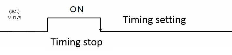
- When M9179 changes from 1 to 0, the set value of R35312~R35318 is written to the corresponding temporary register in RTC. After M9179 returns to 0, the timing action starts, and at the same time, the CPU will reversely retrieve the time value in the RTC and write it to R35312~R35318 for each scan.
- Note: If you want to load the set values into RTC, you must first make M9179 as 1 and then load the set values into R35312~R35318. The loading of the set values into R35312~R35318 can be done via MOVE instruction. However, you must first halt the RTC read out (make M9179 as 1), otherwise the data that you just wrote into R35312~R35318 will immediately be overridden by the time data being read back from RTC in the opposite direction.
- RTC readout (RTC→R35312~R35319):
Whenever the M9179 relay is 0 (RTC timing active). With every scan, CPU will take the time value
data within RTC and move it to R35312~R35319. When it is 1, it will not read out. In this case
R35312~R35318 can load in the set values and they won’t be overridden.
- ±30 second adjustment:
At the moment that the status of relay M9180 goes 1, CPU will check the value of the second register
(R35312) within RTC. If its value is between 0 and 29 seconds then it will be cleared to 0. If its value is
between 30 and 59 seconds then besides being cleared to 0, the minute register (R35313) will be
increased by 1 (i.e., one minute will be added).
- This can be used to adjust your RTC time value. That is, when the RTC time is slow, you can clear it when the value of the second register (R35312) is between 30 to 59 seconds (M9180 changes from 0 to 1), at this time, the time can be adjusted faster due to the minute carry; otherwise, when R35312 clears it at 0-29 seconds, the time can be adjusted slower.
- M9181 RTC installation detecting flag:
When RTC is fitted to the PLC, relay M9181 will be set as 1; otherwise, it will be 0.
- M9182 set value error flag:
When the time value which is set to RTC’s IC is illegal, then the error flag relay M9182 will be set as 1, and the setting action will not be executed.
Note: Before shipping, the time of the main unit has already been set up properly, so a customer usually is not required to set it again when using it. However, if you need to reset by yourself, in addition to using your ladder diagram program and follows RTC setting method (the control of M9179) to make settings; with the software UperLogic, we provide more convenient setting function. As long as you enter the time you want to set, press the set button to complete the setting, and you don’t need to deal with the control of M9179, please refer to the calendar feature of the software manual.
3-1-3 Setting Calendar (RTC) with UperLogic
By setting with the software UperLogic, it allows users to set up the calendar time(RTC) without the need of using special M9179 relay and Ladder control function. The steps described below are the corresponding setting and operation methods:
- Open the UperLogic and then connect it to the PLC that will be set.
- In the upper left tool bar, click PLC-> PLC set -> RTC.
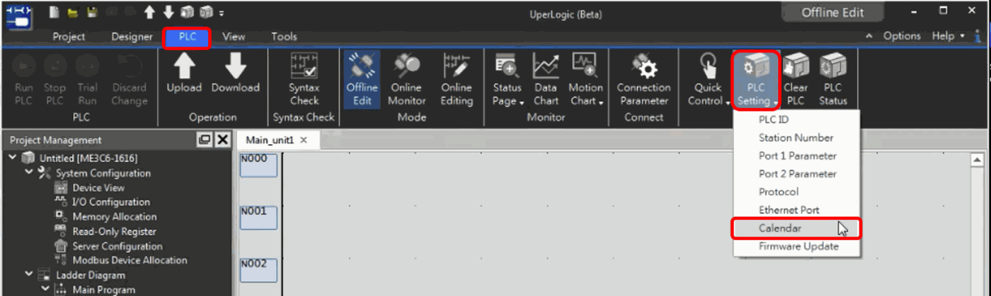
Figure 2 Selections of RTC Settings
- After being selected, the following page will be exported.
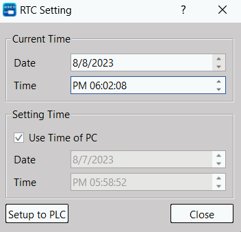
Figure 3 Window of RTC Settings
- Adjust the time that will be set and then click the “Set to PLC” option.
Instructions and notice for the RTC setting window:
- “Current Time” column: The current time retrieved from PLC under online status.
- “Set Time” column: Tick “Use PC Time” and the PC time will be displayed in the lower-side column. Next, press the “Set to PLC” button and “Current Time” will be changed to current PC time.
- When cancelling the ticking of “Use PC Time”, you may change the “Date” and “Time” in the lower-side column as required. Next, press the “Set to PLC” button again and “Current PLC Time” will be changed to the time being set currently.
- When the PLC stops running, you cannot set the RTC and the picture below will appear.
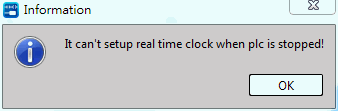
Figure 4 RTC setting is not available when the PLC stops running.
3-2 Network Time Synchronization Settings
The built-in network provides the NTP function, users can enable time synchronization, and easily achieve regular time synchronization through the configured network server and related setting.
Click Project ->Server Configuration ->NTP ->Timezone to synchronize (Disable->Enable) and then set up the cycle time and the time zone that will be synchronized.
|
Function |
Description |
|
Enable Time Synchronization |
Enable NTP Function |
|
Synchronizing Cycle (Minute) |
Set NTP Time Synchronization (1~1440 minutes) |
|
Time Zone |
Set NTP Time Zone Synchronization |
|
NTP Server Address |
Set NTP Server Synchronization |
If the PLC network maintains normal communication after downloading the Project to PLC, it will run the first round of time synchronization and then execute the synchronization according to the designed synchronizing cycle. If the PLC network is unsteady after being started, the synchronization will be executed during next synchronizing cycle.
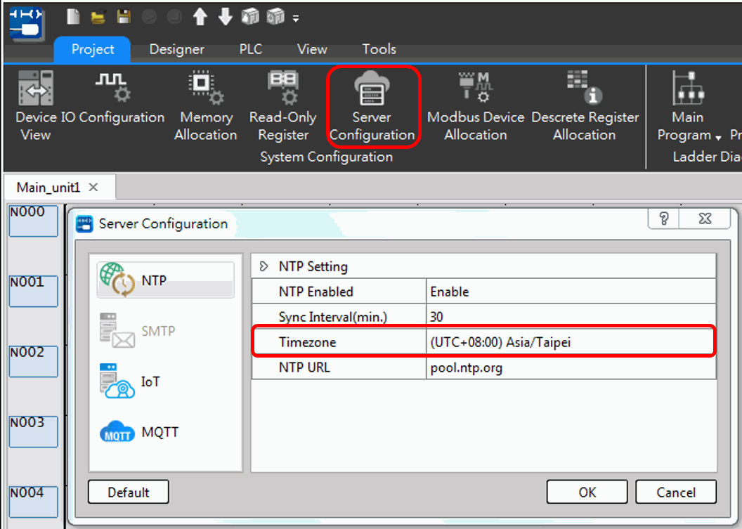
Figure 5 Setting of time synchronization on server
3-3 Time Base
The time base includes:
- Cyclic Pulse Function for use with the cycle-triggered special relay.
- A Timer for dealing with the time event through polling or interruption method.
3-3-1 Type of time base
Cyclic pulse
The cycle of special relay that will change cyclically is fixed such as M9127 0.01s cyclic pulse, etc. It can be switched between ON and OFF according to 0.01s of fixed cycle. It allows the designer to apply in the change of fixed time, as per the figure below:
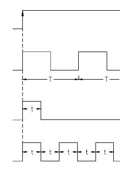
Figure 6 Schematic Diagram of Cyclic Pulse (0.01s)
Its time cycle comprises the following for patterns, i.e., 0.01s cycle, 0.1s cycle, 1s cycle and 60s cycle. For the corresponding relays, please refer to 3.3.2 of this Manual.
Time-setting Timer
During the setting cycle, such time base will interrupt the program being run by the PLC in order to run the program process designed by the user in the interrupted sub-program. When running the program to RTI (Return from Interruption), it will return to the interrupted time-point in order to continue the operation. Its time unit comprises the following for patterns, i.e., 0.1ms, 1ms and 10ms. For the corresponding relays and the available number, please refer to 3.3.2 of this Manual.
Supportive Timer types are as following:
- 0.1ms time-setting HSTA cycling counting
- 0.1ms time-setting HST
- 1ms time-setting timer STM
- 10ms time-setting timer LTM
3-3-2 Example of using Time Base
Example of cyclic pulse
Taking 0.01s cyclic pulse relay for example, its Ladder program is shown as below:

Figure 7 The program example of cyclic pulse
Description of example:
In the program example, Y0 will keep changing according to 0.01s cycle because M9127 Relay will keep outputting 0->1 and 1->0 change to Y0 by using 0.01s as the cycle.
Example of Time-setting Timer
With HST 0 Relay using 0.1ms time base for example, its Ladder program is shown as below:
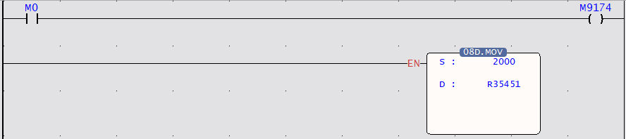
Figure 8 The main program of cyclic pulse
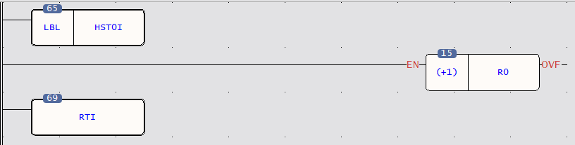
Figure 9 The interrupt sub-program example of cyclic pulse
Description of example:
After finishing the program running, the system will move “2000” to “R35451 0.1ms” for setting the timing at “HST 0” cycle. When “M0 ON”, M9174 will be “ON” and it means HST 0 is active and it will change HST 0 cycle to 2000*0.1ms=0.2s and it means that the program currently run by the PLC will be interrupted every 0.2s. Next, the PLC will enter Sub-program HST01 for running “R0+1” action. After that, the PLC will run the program process that has not been finished during the previous step.
Regarding the detailed description and the introduction of interruption, please refer to Chapter 5: Interruption Function.
3-3-3 List of time base special relay
|
Register No. |
Register Name |
|
M9127 |
0.01s Cyclic pulse |
|
M9128 |
0.1s Cyclic pulse |
|
M9129 |
1s Cyclic pulse |
|
M9130 |
60s Cyclic pulse |
|
M9166 |
1ms Timer STM 0 Control |
|
M9167 |
1ms Timer STM 1 Control |
|
M9168 |
1ms Timer STM 2 Control |
|
M9169 |
1ms Timer STM 3 Control |
|
M9170 |
10ms Timer LTM 0 Control |
|
M9171 |
10ms Timer LTM 1 Control |
|
M9172 |
10ms Timer LTM 2 Control |
|
M9173 |
10ms Timer LTM 3 Control |
|
M9174 |
0.1ms Timer HST 0 Control |
|
M9175 |
0.1ms Timer HST 1 Control |
|
M9176 |
0.1ms Timer HST 2 Control |
|
M9177 |
0.1ms Timer HST 3 Control |
|
M9178 |
0.1ms Timer HSTA loop count control |
Table 4 Table of time base special relay
3-3-4 List of special register
|
Register No. |
Register Name |
Description of Register |
|
R35435 |
1ms timer STM 0 cyclic setting |
Set value of STM0 interrupt |
|
R35436 |
1ms timer STM 0 current time |
Current value of STM0 |
|
R35437 |
1ms timer STM 1 cyclic setting |
Set value of STM1 interrupt |
|
R35438 |
1ms timer STM 1 current time |
Current value of STM1 |
|
R35439 |
1ms timer STM 2 cyclic setting |
Set value of STM2 interrupt |
|
R35440 |
1ms timer STM 2 current time |
Current value of STM2 |
|
R35441 |
1ms timer STM 3 cyclic setting |
Set value of STM3 interrupt |
|
R35442 |
1ms timer STM 3 current time |
Current value of STM3 |
|
R35443 |
10ms timer LTM 0 cyclic setting |
Set value of LTM0 interrupt |
|
R35444 |
10ms timer LTM 0 current time |
Current value of LTM0 |
|
R35445 |
10ms timer LTM 1 cyclic setting |
Set value of LTM1 interrupt |
|
R35446 |
10ms timer LTM 1 current time |
Current value of LTM1 |
|
R35447 |
10ms timer LTM 2 cyclic setting |
Set value of LTM2 interrupt |
|
R35448 |
10ms timer LTM 2 current time |
Current value of LTM2 |
|
R35449 |
10ms timer LTM 3 cyclic setting |
Set value of LTM3 interrupt |
|
R35450 |
10ms timer LTM 3 current time |
Current value of LTM3 |
|
R35451 |
0.1ms timer HST 0 cyclic setting LOW WORD |
LOW WORD of the set value of HST0 interrupt |
|
R35452 |
0.1ms timer HST 0 cyclic setting HIGH WORD |
HIGH WORD of the set value of HST0 interrupt |
|
R35453 |
0.1ms timer HST 0 current time LOW WORD |
LOW WORD of the current value of HST0 |
|
R35454 |
0.1ms timer HST 0 current time HIGH WORD |
HIGH WORD of the current value of HST0 |
|
R35455 |
0.1ms timer HST 1 cyclic setting LOW WORD |
LOW WORD of the set value of HST1 interrupt |
|
R35456 |
0.1ms timer HST 1 cyclic setting HIGH WORD |
HIGH WORD of the set value of HST1 interrupt |
|
R35457 |
0.1ms timer HST 1 current time LOW WORD |
LOW WORD of the current value of HST1 |
|
R35458 |
0.1ms timer HST 1 current time HIGH WORD |
HIGH WORD of the current value of HST1 |
|
R35459 |
0.1ms timer HST 2 cyclic setting LOW WORD |
LOW WORD of the set value of HST2 interrupt |
|
R35460 |
0.1ms timer HST 2 cyclic setting HIGH WORD |
HIGH WORD of the set value of HST2 interrupt |
|
R35461 |
0.1ms timer HST 2 current time LOW WORD |
LOW WORD of the current value of HST2 |
|
R35462 |
0.1ms timer HST 2 current time HIGH WORD |
HIGH WORD of the current value of HST2 |
|
R35463 |
0.1ms timer HST 3 cyclic setting LOW WORD |
LOW WORD of the set value of HST3 interrupt |
|
R35464 |
0.1ms timer HST 3 cyclic setting HIGH WORD |
HIGH WORD of the set value of HST3 interrupt |
|
R35465 |
0.1ms timer HST 3 current time LOW WORD |
LOW WORD of the current value of HST3 |
|
R35466 |
0.1ms timer HST 3 current time HIGH WORD |
HIGH WORD of the current value of HST3 |
|
R35467 |
0.1ms HSTA loop current count LOW WORD |
LOW WORD of the current value of HSTA |
|
R35468 |
0.1ms HSTA loop current count HIGH WORD |
HIGH WORD of the current value of HSTA |
Table 5 Table of time base special relay
Tip: press ← → to switch chapters, Ctrl+K to search