|
⚠Danger |
|
This section describes the procedure where the comment function is used to improve the program readability and to facilitate maintenance in the future. Such descriptive comment is also available for components, network or program unit. In the meantime, this section also explains the function designed for hiding or displaying the comment.
8-1 Program Unit Comment
When running several program units, the user will be required to set up the comment for the respective program unit in order that the checking and modification will be executed more easily in the future.
Input descriptive comment for program unit: For detailed operation method, please refer to the description provided in Section 6.1.5: “Input Program Unit Comment.”
Modify descriptive comment for program unit: After being imported, the user will be allowed to change the program according to the imported comment or to show the modification field by double clicking the comment text field in the Ladder Diagram program field. In this way, the user will be allowed to change the comment text.
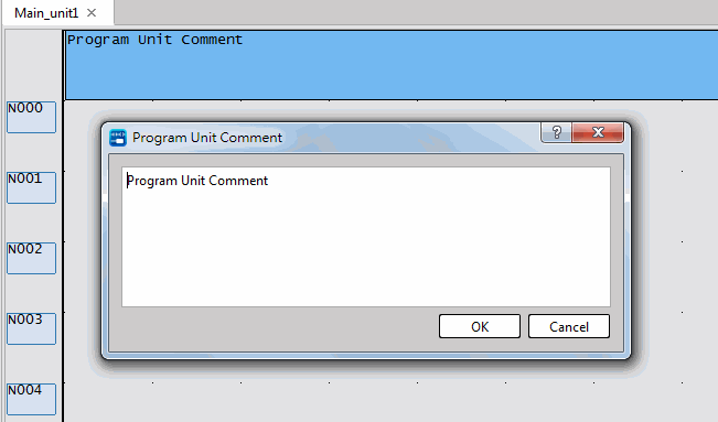
Fig. 139: Program unit comment
8-2 Network Comment
Each program unit comprises several network comments and each of them is designed with the intended function. By using such function with the comment, it will be easier for program modification and maintenance in the future.
8-2-1 Operation method for inputting comment in dedicated comment field
Click [Project] → [Comment] → [Network Comment] in function toolbar, or double clicking [Comment] → [Network Comment] in project management window and the [Network Comment] input window will be displayed:
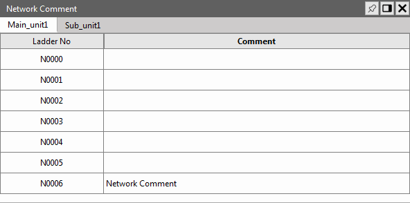
Fig. 140: Network Comment
The comment input method shall be the same as the operation instructions provided in Section 6.1.5: “Input Program Unit Comment”. After being imported, press [OK] to complete the comment setting for the network comment.

Fig. 141: Inputting network comment
8-2-2 Operation method for inputting comment by selecting Single Solution Network
In Ladder Diagram program section, you may click Network N000 or its component and then press the right mouse button to show Pop-up Menu in order to select the [Network Comment]. By clicking the right mouse button to show the function menu, it allows the user to select [Network Comment] function. At this time, the system will show the network comment input section that represents “Network N000.”
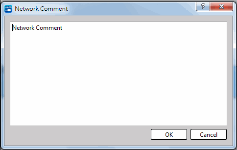
Fig. 142: Editing network comment
Press [OK] to complete the editing of comment for network comment.
Modifying network descriptive comment
For detailed operation method, please refer to Section 6.1.5: “Inputting Program Unit Comment.”
Deleting network descriptive comment
For detailed operation method, please refer to Section 6.1.5: “Inputting Program Unit Comment.”
8-3 Element Comment
The program unit is composed of several network comments where each component is also serving as a single network comment. Under such structure, lots of components exist in each Single Program Unit that it would be required to provide comment description for each component.
8-3-1 Setting Introduction
Click [Project] → [Comment] → [Element Comment] in function toolbar; or double clicking [Comment] → [Element Comment] in project management window and the [Element Comment] input sectoin will be displayed:
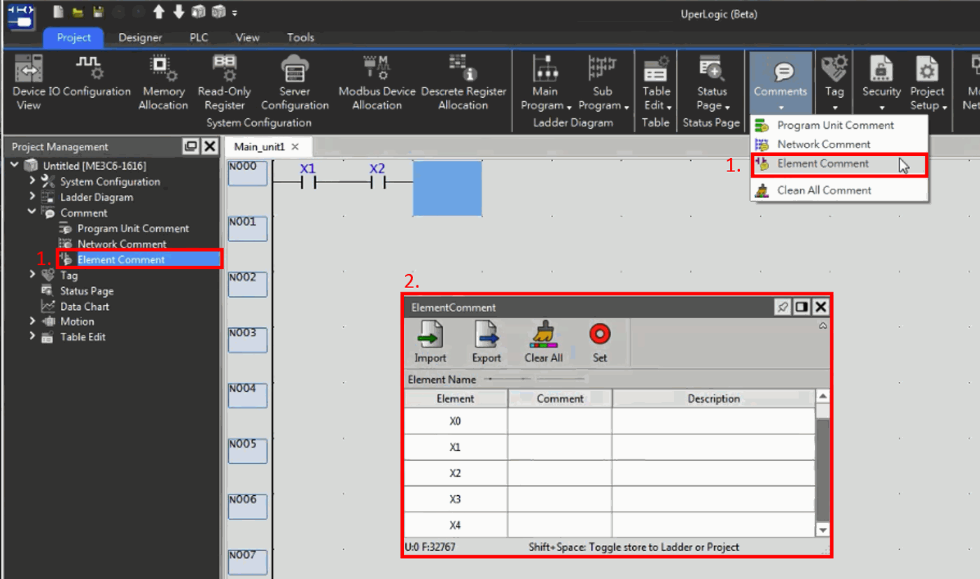
Fig. 143: Element comment
Element Comment_Import:
First select the file that will be imported. Next, select the column item to be imported and then press [OK].
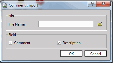
Fig. 144: Element comment_import
Element Comment_Export:
First select the file that will be exported. Next, select the column item to be exported and then press [OK].
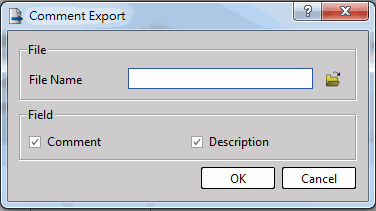
Fig. 145: Element comment_export
Element Comment_Clear All:
Delete all of the comment and description currently created.
Element Comment_Element Name:
Executing the GoTo function for entering the selected Register number address automatically.
Component Comment_Set:
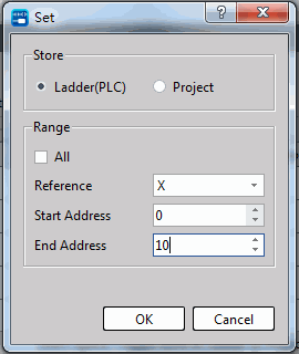
Fig. 146: Element comment_setting
|
Type |
Function |
Description |
|
Saving position |
PLC |
Save the comment in the PLC and the occupied resources will be displayed at the lower-left corner of “Component comment” window. |
|
Project |
Save the comment in the Project and will not occupy the PLC resources. |
|
|
Scope |
All |
Change all components to the selected saving position. |
|
No. |
Select the component number. |
|
|
Start address |
Select the starting address of the component comment. |
|
|
End address |
Select the ending address of the component comment. |
Table 18: Introduction of items in equipment window
8-3-2 Operation method
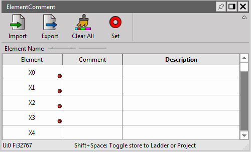
Fig. 147: Element comment window
With [Set] or “Shift+Space” quick keys, you may switch the component comment saving position. The red circle at the lower-right side of the component means that the component has been saved in the project instead of downloading to the PLC.
The field display at lower-left side represents the quantity (U) currently used and the remaining quantity (F).
8-4 Controlling of Comment Display
In Ladder Diagram, the program field is used for displaying program unit comment, network comment and component comment, etc. Described below is the operating method designed for displaying or hiding the aforesaid comments:
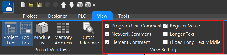
Fig. 148: Comment display
Click [View] → [Program Unit Comment] in function toolbar. If the “√“ symbol is not marked on the left side of text option, then the comment text will not be displayed at the upper side of the program field in Ladder Diagram. After completing such action, the “√“ symbol will appear on the left side of text option.
Such procedure also applies to Element Comment, Network Comment and Register Value.
8-5 Tag
Tags are variables that are specified as arbitrary strings for input, output, and internal data. Tags can be designed to express the logic of the program more clearly through string descriptions. Programs using tags can also easily modify the variable configuration without modifying them one by one.
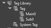
There are two types of UperLogic tags: global tags, and system tags.
|
Item |
Description |
|
Global Tag |
Tags that can be used by all programs and settings in the project. Each program will automatically be configured with tags to classify the program, making it convenient for customers to classify and manage. It can also be used in different programs and can be created by themselves. Users can quickly access the corresponding tab settings from the Tag below each program unit.
|
|
System Tag |
The default label of M-PLC cannot be created by oneself. |
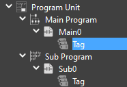
[Note] If user want to encapsulate FCM function blocks, you need to pay attention to the use of global register types and global tags, such as: R/D/M. This avoids misuse and manipulation of duplicate register locations by other programs during calls, resulting in logic malfunctions. If you need to completely encapsulate the FCM, you must use only FCM local variables (Local Variable) in the FCM program. Please refer to the FCM chapter for details.
8-5-1 Tag Editor
Tags can be edited and exported through the following tag editor. The following describes each function.。
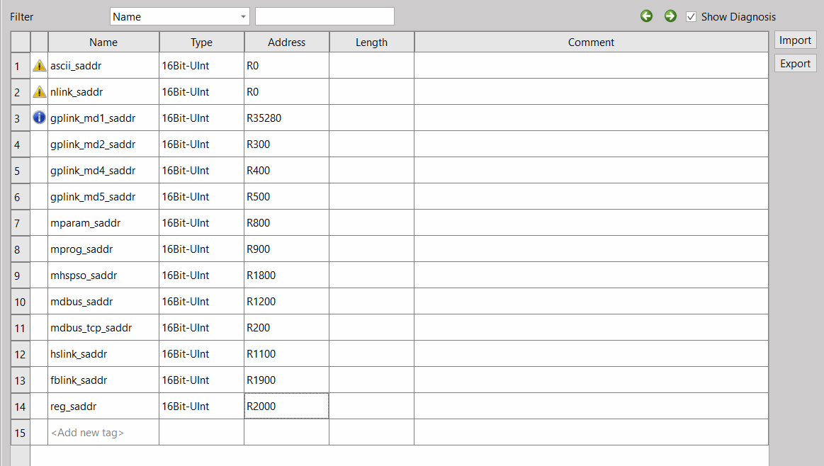
- Filter Out
According to the category selected by the user to be filtered out and the input content, the tags that will be kept on the screen are determined. Filterable categories include Name, Type, Address, Length, Comments, and None.
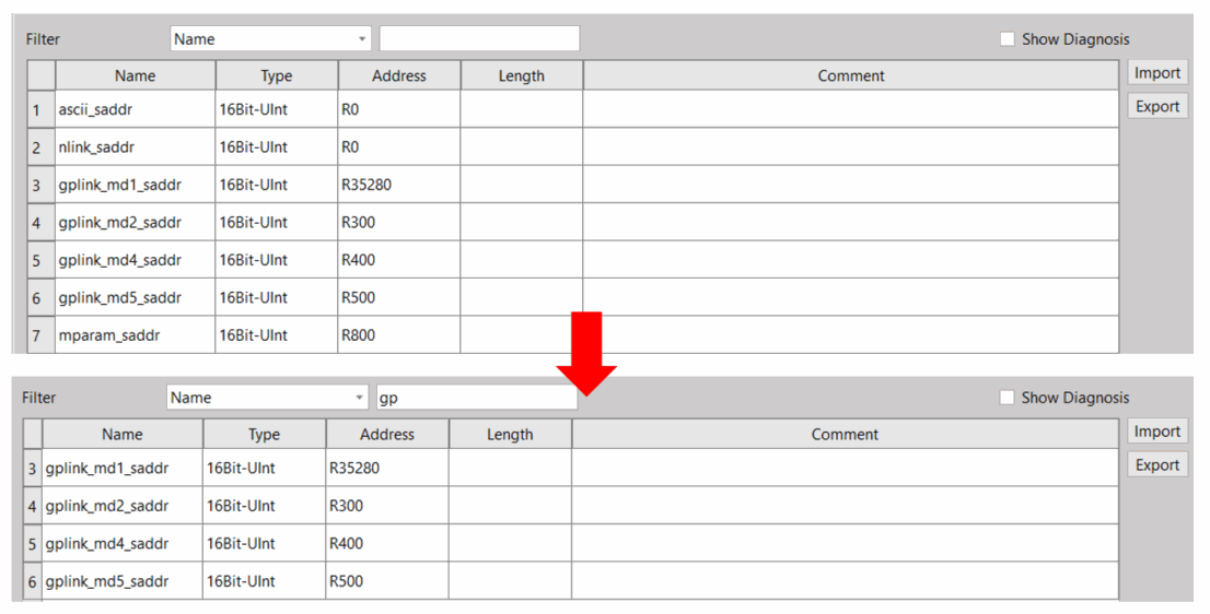
Fig. 149: Filtering out tags
- Display Diagnosis
When the user checks [Display Diagnosis] on the right, a column will be added in front of the tag name, and the diagnosis result will be represented by an icon. When the icon is double-clicked, the details of the diagnosis window will be displayed.
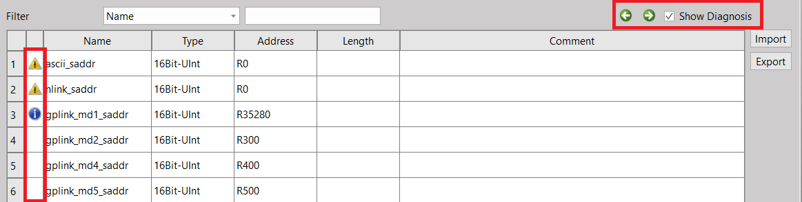
Fig. 150: Display diagnostic result
|
Item |
Description |
|
|
Jump to the previous diagnostic result. |
|
|
Jump to the next diagnostic result. |
|
|
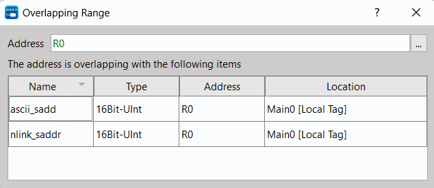
Indicates that the tag address overlaps with other labels. After double-clicking the prompt, the details will be displayed. When the user double-clicks the overlapping item, it will directly jump to the tag editing page where the item is located. This function can remind the designer to avoid reusing the same register location, which may lead to program logic malfunction。
|
|
|
Indicates that the tag address overlaps with a special relay or a special register. |



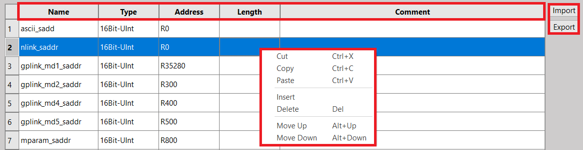
- Editing Section
Including table section, button section and right-click menu, details are as follows:
|
Item |
Description |
|
|
Table |
Name |
Set a tag name, the maximum length is 32 characters. It cannot be pure numbers, registers and reserved words. |
|
Type |
Set tag data type, the types are divided into: [Bool] [16Bit-Int] [16Bit-UInt] [32Bit-Int] [32Bit-UInt] [Float] |
|
|
Address |
Set the register or relay address assigned to the tag. |
|
|
Comment |
Set the comment of the tag. |
|
|
New |
After clicking, a row of tags will be added in the editing section for users to edit. |
|
|
Delete |
After clicking, delete the tag currently selected by the user, and multiple selections can be deleted. |
|
|
Import |
After clicking, the tag will be imported after selecting the file. The file extension is *.csv |
|
|
Export |
After clicking, the tag can be exported after selecting the storage location. The file extension is *.csv |
|
|
Right-Click Menu |
Cut |
After clicking, cut the tag currently selected by the user, and multiple selections can be cut. |
|
Copy |
After clicking, copy the tag currently selected by the user, multiple selections can be copied。 |
|
|
Paste |
After clicking, paste the tag previously copied or cut by the user. |
|
|
Insert |
After clicking, insert a row of tags at the selected position in the editor for users to edit. |
|
|
Delete |
After clicking, delete the tag currently selected by the user, and multiple selections can be deleted. |
|
|
Move Up |
After clicking, move the tag currently selected by the user up one column. |
|
|
Move Down |
After clicking, move the tag currently selected by the user down one column. |
|
8-5-2 Tag
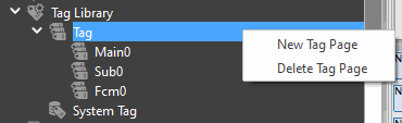
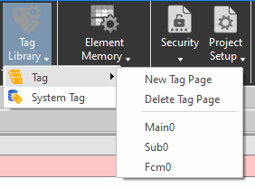
The tag editor can be edited through [Tag Library] → [ Tag] in the project management window or in the function bar [Project] → [Tag Library] → [Tag].
Users can create global tabs by themselves through [Add Tag] and [Delete Tag]. The name of the tag pages and all tags cannot be the same.
 d
Fig. 151: Global Tags
8-5-4 System Tag
The list of system tags can be viewed through [Tag] → [System Tag] in the project management window or by clicking [Project] → [Tag] → [System Tag]. The system label is a built-in label, which varies with different models. It is only for viewing, and cannot be added or edited. The name of the system tag must start with $ font size.
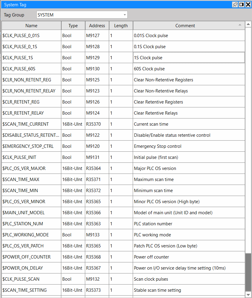
Fig. 153: List of System Tags
There are many tag groups in the system tag, users can view the labels of different categories by selecting a tag group.
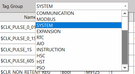
Fig. 154: Tag group menu
8-5-5 Tag Usage
- Direct Use
During the editing process, the user can directly input the relevant words of the corresponding tag name, and a drop-down menu will appear at this time to prompt possible tags to be used. 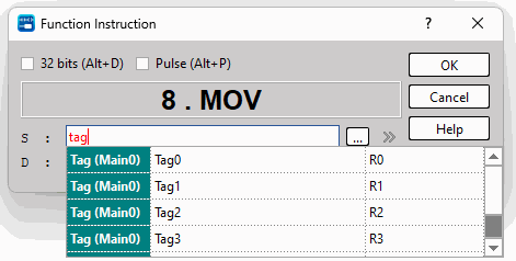
Fig. 155 Tags
- Use after processing a new tag
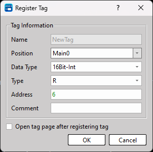
If the user wants to directly create a new tag and use it during the editing process, he can directly enter the name of the new tag and press “Enter”, and the system will automatically jump to the registration tag window to allow the user to register a new tag.
|
Item |
Description |
|
Name |
Tag Name |
|
Position |
The registration position of the Tag can be set in a specific Tag page |
|
Type |
Set tag data type, the types are divided into: [Bool] [16Bit-Int] [16Bit-UInt] [32Bit-Int] [32Bit-UInt] [Float] |
|
Address |
Set the register or relay address assigned to the tag |
|
Comment |
Set the comment of the tag |
|
Open the Tag Page after Registration |
When checked, it will jump to the tag editor page after the registration is complete. |
Tip: press ← → to switch chapters, Ctrl+K to search