Chapter11.Tuning Software(ProTuner)



Using the host computer software (ProTuner), the following functions can be realized online: • Parameter management: parameter setting and adjustment
• Status monitoring: Monitor the working status and related data of the servo system
• Use tracking: Use tracking for servo power, instructions, output current and other related data • Auxiliary debugging: realize online auxiliary debugging of servo functions using the host computer
|
11.1 ProTuner Connect and login |
|
|
1. Install the ProTuner debugging software on the PC 3. After the communication line is correctly connected, execute the ProTuner debugging software on the PC |
|
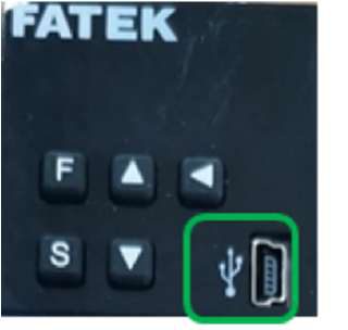
(as shown in the picture).
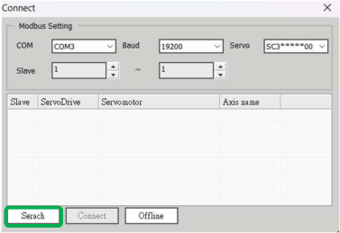
When the [User Login] window is displayed, click the [Search] button (Figure 1).
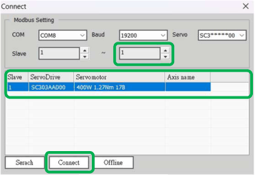
4. After the [Connect] window is displayed, select the searched drive address 1 or address 2, and then click the [Connect] button (Figure 2).
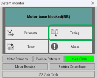
5. After the connection is successful, the [System Monitoring] shortcut window (Figure 3) and [ProTuner] debugging window (Figure 4) will be displayed.。
|
|
|
|
|
|
|
Figure 3 |
||||
|
Figure 1 |
Figure 2 |


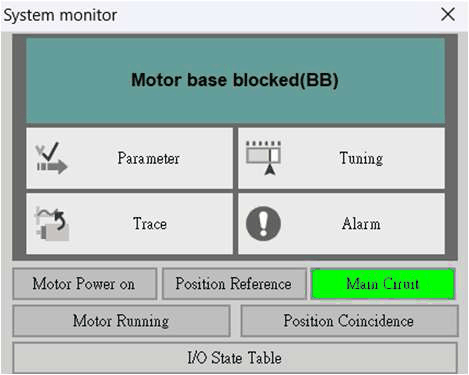
At this time, the ProTuner debugging software is successfully connected.
•In the [ProTuner] debugging window, you can selectively monitor various statuses of the servo in each window.
•In the menu bar of the [ProTuner] debugging window, you can click the debugging shortcut button to enter the debugging interface.。
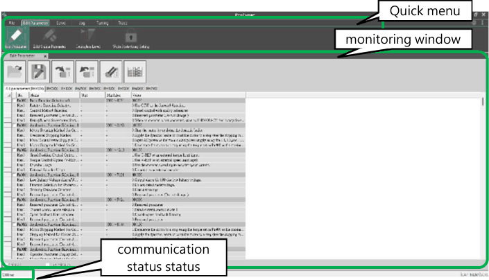
Figure 4
11.2 Automatic Adjustment (No Upper-Level Commands)
Automatic Adjustment (No Upper-Level Commands) refers to the functionality where the servo unit operates autonomously (reciprocating motion in both forward and reverse) without receiving commands from upper-level devices, and adjusts itself during operation based on mechanical characteristics.
The automatic adjustment items are as follows:
• Moment of inertia ratio
• Gain adjustment (speed loop gain, position loop gain)
• Filter adjustments (torque command filter, notch filter)
• Friction compensation
• Anti-resonance control
• Vibration suppression



Automatic Adjustment (No Upper-Level Commands) adjustment is explained.
• Automatic Adjustment (No Upper-Level Commands)Adjust based on the set speed loop gain (Pn100). If vibration occurs at the beginning of adjustment, correct adjustment will not be possible. Please reduce the speed loop gain (Pn100) until the vibration no longer occurs and then make adjustments.
• Automatic Adjustment (No Upper-Level Commands) cannot be executed while the adjustment-free function is enabled (Pn170= n.▯▯▯1 [Default Setting]). Please disable the adjustment-free function (Pn170 = n.▯▯▯0) before making adjustments.。 • After executing Automatic Adjustment (No Upper-Level Commands), change the load status or transmission mechanism of the machine, and set the "estimated moment of inertia" again. When executing Automatic Adjustment (No Upper-Level Commands), please refer to the following setting parameters. If automatic adjustment is performed in a state other than the following (without upper bit command), it may cause mechanical vibration and damage to the machine.。
Pn140 = n.▯▯▯0 (Not using model tracking control)
Pn160 = n.▯▯▯0 (Not using anti-resonance control)
Pn408 = n.00▯0 (Not using friction compensation, first-stage and second-stage notch filters)
NOTE: When using a digital operator, if the above parameters are not displayed, please select the setting to display all parameters (Pn00B = n.▯▯▯1) and then power cycle the device.
■Things to confirm before execution
Before executing Automatic Adjustment (No Upper-Level Commands), please ensure the following settings are confirmed: • Main Circuit Power supply must be ON。
• There must be no over-travel.
• The system must be in the servo OFF state.
• Torque control must not be active.
• The gain switch must be set to manual gain switching (Pn139 = n.▯▯▯0).
• The first gain must be selected.
• No error alarms or warnings should be present.
• STO must be in the OFF state *1.
• The write protection setting for parameters must not be set to "Write Prohibited."
• The adjustment-free function must be disabled (Pn170 = n.▯▯▯0), or if the adjustment-free function is enabled (Pn170 = n.▯▯▯1), it must be set to "Estimated Moment of Inertia."
• When executing in speed control mode, the mode selection must be set to 1.
*1: STO is an optional feature.
■Operation steps
1、Confirm that the moment of inertia ratio has been set correctly (Pn103).
2、Connect the servo drive, and in the ProTuner [System Diagnostics] window, click the [Tuning] button in the workspace (see Figure 5).
Alternatively, click the tuning shortcut button from the context menu in the [ProTuner] debugging window( )。
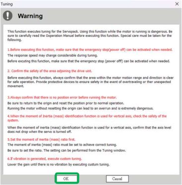
3、In the [Tuning] window, click the [Execute] button (see Figure 6).
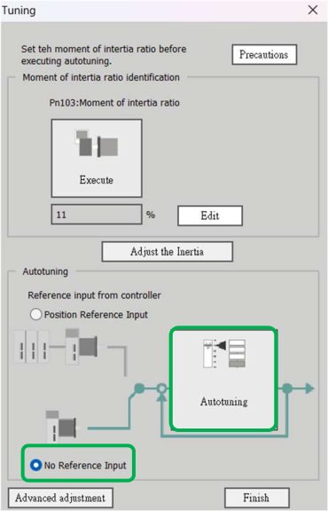
4、Enter the [Tuning Axis] window (see Figure 7).
• Select the [Automatic Adjustment] group.
• Choose [No Reference Input].
• Click the [Automatic Adjustment] button.
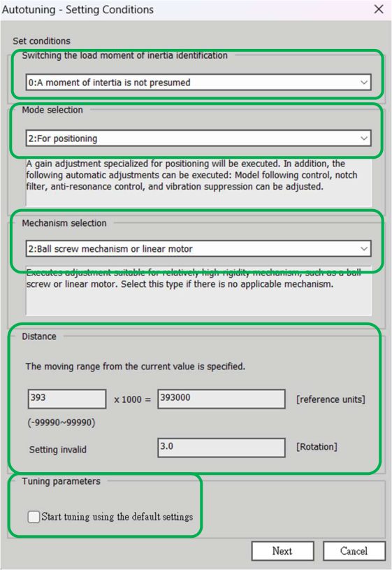
5、Enter the [Automatic Adjustment Setting Conditions]
window (see Figure 8) and set the following:
• [Switch Load Inertia (Load Quality) Estimation] field • [Mode Selection] field
• [Mechanism Selection] field
• [Distance] field
|
• [Adjustment Parameters] field Then click【Next】
|
|
|
Figure 5 |
Figure 6 |
Figure 7 |
|
|||||||||||||||||||||
|
|
||||||||||||||||||||
6、Enter the [Auto Adjustment] window
Click the [Servo On] button( ),to energize the servo motor.
Next, click the [Start Adjustment] button( ),the servo motor rotates and the adjustment is performed.
|
|
|
|
|
|
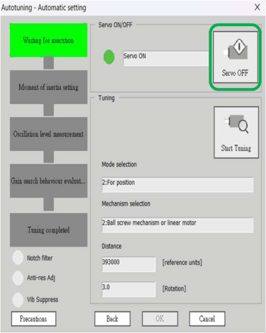

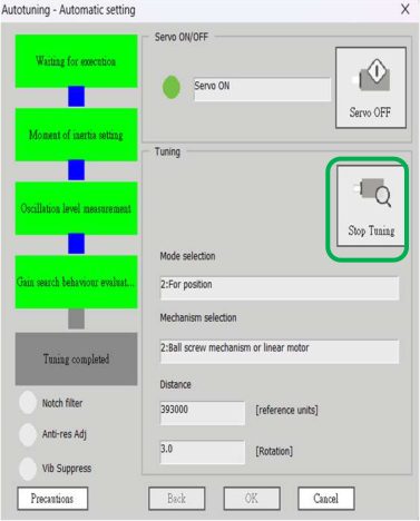

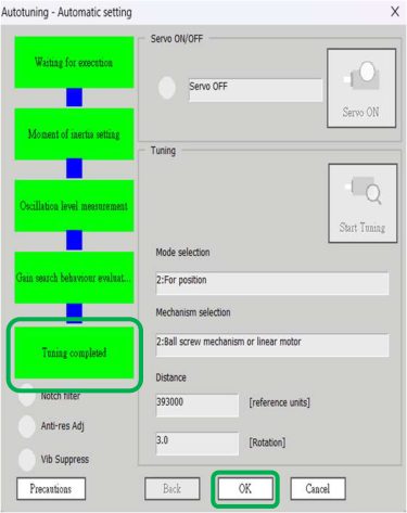
Automatically detects vibration generated during adjustment and makes optimal settings for the generated vibration. After the setting is completed, the executed function box will light up.
7、After the adjustment is completed, click the [Finish] button to return to the [Tuning Axis] window. At this point, the operation of Automatic Adjustment (No Upper-Level Commands) is completed.
Common Error Alarms
1.Error alarm when powering on for the first time [A.810] Encoder backup error alarm:
Pn002【Application Function Selections 2】:▯1▯▯
|
n.▯X▯▯ |
Encoder Usage |
|
|
0 |
Use the encoder according to encoder specifications. |
|
|
1 |
Use the encoder as an incremental encoder. |
|
|
2 |
Use the encoder as a single-turn absolute encoder. |
|
2.Error alarm when powering on for the first time [A.F10] The power line is missing a phase (in the Main Circuit PowerON state, one of the L1, L2, and L3 phases has a low voltage state that lasts for more than 1 second)
Pn00b【Application Function Selections B】:▯1▯▯
|
n.▯X▯▯ |
Power Input Selection for Three-phase SERVOPACK |
|
|
0 |
Use a three-phase power supply input. |
|
|
1 |
Use a three-phase power supply input as a single-phase power |
|
Common parameters【X set parameter position】
1.Motor Direction Change
Pn000【Basic Function Selections 0】:0000【Factory settings】
|
n.▯▯▯X |
Movement Direction Selection |
|
|
0 |
Use CCW as the forward direction.。 |
|
|
1 |
Use CW as the forward direction. (Reverse Rotation Mode) |
|
2.Rigid setting(Pn100, Pn101, Pn102)and Inertia setting(Pn103)
|
Paramete r No. |
Size |
Name |
Setting Range |
Setting Unit |
出廠設定 |
|
Pn100 |
2 |
Speed Loop Gain |
10~20000 |
0.1 Hz |
400 |
|
Pn101 |
2 |
Speed Loop Integral Time Constant |
15~51200 |
0.01 ms |
2000 |
|
Pn102 |
2 |
Position Loop Gain |
10~20000 |
0.1/s |
400 |
|
Pn103 |
2 |
Moment of Inertia Ratio |
0 ~20000 |
1% |
100 |
3.Control filter selection
Pn200【Position Control Reference Form Selections】:0000【Factory settings】
|
n.X▯▯▯ |
Filter Selection |
|
|
0 |
Use the reference input filter for a line-driver signal. (1 Mpps max.) |
|
|
1 |
Use the reference input filter for an open-collector signal. (200 page 6-31 kpps max.) |
|
|
2 |
Use reference input filter 2 for a line-driver signal. (1 to 4 Mpps) |
|
4.Electronic gear ratio setting
Pn20E【Electronic Gear Ratio(Numerator)】:131072【17 Bit encoder】;8388608【23Bit encoder】 Pn210【Electronic Gear Ratio(Denominator)】:1000
5.Operation settings
Pn50A【Input Signal Selections 1】:
8881【"Forward rotation side can be driven"; enable: power on enable】
0881【"Forward rotation side can be driven"; enable:Enable forward drive when CN1-IN0 input signal is ON (closed).】 Pn50B【Input Signal Selections 2】: 8889【“Set the signal to always prohibit forward drive.”】
Tip: press ← → to switch chapters, Ctrl+K to search