CPU Interface and Peripheral Functions
5-1 Instructions for CPU Panel Interface and Functions
5-1-1 Advanced type Module
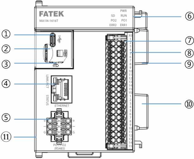
CPU Module diagram (Advanced type)
|
No. |
Name |
Function |
|
1. |
USB connector |
For connecting Type C data cable |
|
2. |
Memory card slot |
The slot is designed for inserting FATEK MicroSD memory card. |
|
3. |
RUN/STOP changeover switch |
For switching between the RUN Mode and STOP Mode. |
|
4. |
RJ-45 (Ethernet) connector |
The connector (RJ-45) designed for network cable connection. The interface designed for connection purposes (for 10BASE-T/100BASETX). |
|
5. |
RS485 communication port |
RS485 communication port. (PORT1.PORT2) |
|
6. |
LED status indicator |
Display CPU status. |
|
7 |
36pin European standard terminal (default) 40pin Box Header Connector (Optional) |
Digital Input / Digital Output connector.. |
|
8 |
I/O output status indicator |
Display the action status of digital I/O. |
|
9 |
FATEK HyperBus Connector |
Connect to high speed or local I/O expansion modules |
|
10 |
FATEK HyperBus Connector |
Connect to high speed or local I/O expansion modules |
|
11 |
Advanced expansion(port) |
Advanced expansion bus: The bus connected to the advanced expansion module |
CPU panel function introduction (Advanced type)
5-1-2 Module with General/Advanced Montion Control
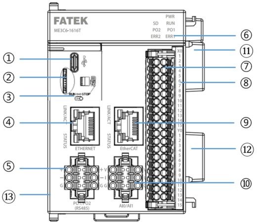
CPU Module diagram (with General/Advanced Motion)
|
No. |
Name |
Function |
|
1. |
USB connector |
For connecting Type C data cable |
|
2. |
Memory card slot |
The slot is designed for inserting FATEK MicroSD memory card. |
|
3. |
RUN/STOP changeover switch |
For switching between the RUN Mode and STOP Mode. |
|
4. |
RJ-45 (Ethernet) connector |
Cable for connecting network cables (RJ-45) Interface for connection (for 10BASE-T/100BASETX). |
|
5. |
RS485 communication port |
RS485 communication port. (PORT1.PORT2) |
|
6 |
LED status indicator |
Display CPU status. |
|
7 |
36pin European standard terminal (default) 40pin Box Header Connector (Optional) |
Digital Input / Digital Output connector.. |
|
8 |
I/O output status indicator |
Display the action status of the digital I/O. |
|
9 |
EtherCAT connector |
EtherCAT communication port |
|
10 |
Analog input |
Simulation quantity input (such function is under development). |
|
11 |
FATEK HyperBus Connector |
Connect to high speed or local I/O expansion modules(MU model not available) |
|
12 |
FATEK HyperBus Connector |
Connect to high speed or local I/O expansion modules |
|
13 |
Advanced expansion(port) |
Advanced expansion bus: The bus connected to the advanced expansion module(MU model not available) |
CPU panel function introduction (General/Advanced Motion Control type)
5-1-3 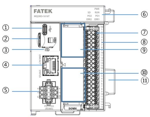 Compact module
CPU Module diagram (with Compact)
|
No |
Name |
Function |
|
1. |
USB connector |
For connecting Type C data cable |
|
2. |
Memory card slot |
The slot is designed for inserting FATEK MicroSD memory card. |
|
3. |
RUN/STOP changeover switch |
For switching between the RUN Mode and STOP Mode. |
|
4. |
RJ-45 (Ethernet) connector |
Cable for connecting network cables (RJ-45) Interface for connection (for 10BASE-T/100BASETX). Also used to support EtherCAT communication servo control equipment (optional) |
|
5. |
RS485 communication port |
RS485 communication port. (PORT1.PORT2) |
|
6 |
LED status indicator |
Display CPU status. |
|
7 |
36pin European standard terminal (default) 40pin Box Header Connector (Optional) |
Digital Input / Digital Output connector.. |
|
8 |
I/O output status indicator |
Display the action status of the digital I/O. |
|
9 |
Plug-in SLOT1 |
Expandable serial communication, network communication, high-speed DIO, AD/DA, RTC board |
|
10 |
Plug-in SLOT2 |
Expandable serial communication, network communication high-speed DIO, AD/DA, RTC board |
|
11 |
FATEK HyperBus Connector |
Connect to local I/O expansion modules |
Introduction to CPU module panel functions (Compact)
5-2 RUN/STOP Changeover Switch
The M-Series CPU Module comprises RUN/STOP modes. Both of them can be shifted with each other through the RUN/STOP Changeover Switch located in the left- side cover plate of the machine.
RUN Mode: Run the program
STOP Mode: Stop running the program
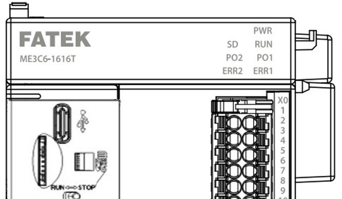
- RUN/STOP operation method
The RUN/STOP method of MPLC can be operated with the following two methods:
(1) Operate through the physical RUN/STOP switch. With the RUN/STOP switch of the CPU Module, you may execute the run/stop procedure. When setting the switch to the RUN position, it means running. When setting the switch to the STOP position, it means stop running.
(2) Execute remote RUN/STOP operation from UperLogic
The UperLogic is designed with a remote operation function to execute the compulsory RUN/STOP of the programming controller (the remote RUN/STOP function). After being restarted, however, the previous remote RUN/STOP function will become inactive. In this case, the RUN/STOP status will be decided by the action of the physical RUN/STOP switch.
2. Combined operations of several RUN/STOP methods
When operating the module with the physical RUN/STOP switch and when the STOP command is given by UperLogic, you may output the RUN command again through the UperLogic or through the STOP→RUN operation of the built-in RUN/STOP switch and the programming control will return to the RUN status.
<Notice> When setting the built-in RUN/STOP switch at the STOP position, the remote RUN function will remain inactive.
5-3 Layout Diagram of Ethernet, EtherCAT Pin
- RJ-45(Ethernet)
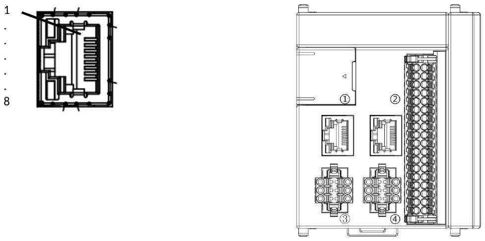
Network port pin layout
|
Terminal No. |
Direction |
Signal name |
|
1 |
TD+ |
Transmitting data (+) |
|
2 |
TD- |
Transmitting data (-) |
|
3 |
RD+ |
Receiving data (+) |
|
4 |
- |
|
|
5 |
- |
|
|
6 |
RD- |
Receiving data (-) |
|
7 |
- |
|
|
8 |
- |
2. RJ-45(EtherCAT)
|
Terminal No. |
Direction |
Signal name |
|
1 |
TD+ |
Transmitting data (+) |
|
2 |
TD- |
Transmitting data (-) |
|
3 |
RD+ |
Receiving data (+) |
|
4 |
- |
|
|
5 |
- |
|
|
6 |
RD- |
Receiving data (-) |
|
7 |
- |
|
|
8 |
- |
5-4 Layout Diagram of RS485, AI Pin
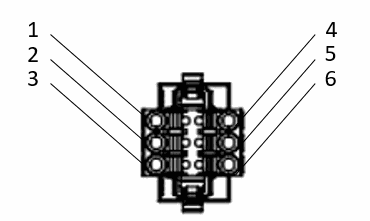
3. RS485
|
Terminal No. |
Direction |
Signal name |
|
1 |
D+ |
D+ of Port1 |
|
2 |
D- |
D- of Port1 |
|
3 |
G(SG) |
signal ground |
|
4 |
D+ |
D+ of Port2 |
|
5 |
D- |
D- of Port2 |
|
6 |
G(SG) |
signal ground |
|
7 |
RSV |
MQ models – reserved for new feature expansion. |
4. AI
|
Terminal No. |
Direction |
Signal name |
|
1 |
VI0 |
Voltage input – ch0 |
|
2 |
II0 |
Current input – ch0 |
|
3 |
GND |
signal ground |
|
4 |
VI1 |
Voltage input – ch1 |
|
5 |
II1 |
Current input – ch1 |
|
6 |
GND |
signal ground |
5-5 Display Inducator of LED Status
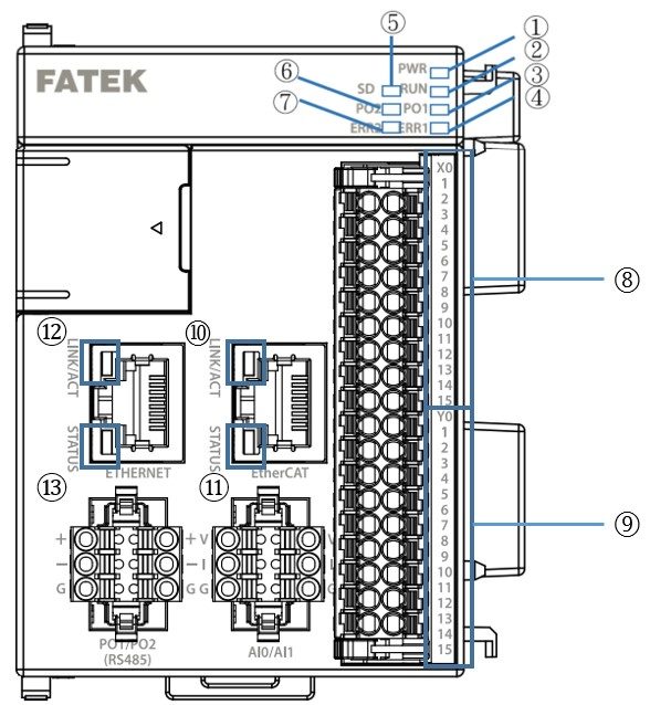
CPU Module indicator schematic view
|
No. |
Name |
Description |
|
1 |
PWR Power indicator: |
Yellowish green. It remains lighted when supplied with power. |
|
2 |
RUN Running indicator: |
Yellowish green. It flickers slowly when the module stops running, but will flicker quickly when the module is running. |
|
3 |
PO1 Port1 Communication Indicator-1: |
Yellowish orange: LED flickers when Port1 is in communication. |
|
4 |
ERR1 Error Message Indicator-1 |
Red: Steady light indicating the warning or major error message. |
|
5 |
SD Memory card signal light: |
Yellowish green: steady light when memory card is inserted. |
|
6 |
PO2 Port2 Communication Indicator-2: |
Orange: LED flickers when Port2 is in communication. |
|
7 |
ERR2 Error Message Indicator-2 |
Red: Steady light indicating the warning or major error message. |
|
8 |
X0~X15 Input Indicator: |
Yellowish green: It will be lighted when the corresponding point (X Point) is under ON status, but will be extinguished when the corresponding point is under the OFF status. |
|
9 |
Y0~Y15 Output Indicator: |
Yellowish green: It will be lighted when the corresponding point (Y Point) is under the ON status, but will be extinguished when the corresponding point is under the OFF status. |
|
10 |
EtherCAT Port LINK/ACT Indicator |
Yellow: When the lamp remains lighted, it means that the network cable has been properly connected. It flickers when EtherCAT network is communicating. When the lamp is extinguished, it means that the network cable is not connected. |
|
11 |
EtherCAT Port STATUS Indicator |
Green Blinking fast:: The system is operating Blinking slowly: The system is under online process. 1-flash: The module has been activated. 2-flash: Error |
|
12 |
Ethernet RJ45 Port LINK/ACT Indicator: |
Yellow: When the lamp remains lighted, it means that the network cable has been properly connected. It flickers when Ethernet network is communicating. When the lamp is extinguished, it means that the network cable is not connected. |
|
13 |
Ethernet RJ45 Port STATUS Indicator |
Green: It flickers when operating under DHCP Mode to indicate that the system is retrieving the IP. When the lamp remains lighted, it means that the IP has been set or retrieved through DHCP. When the lamp remains dark, it means that the IP is invalid. |
CPU panel LED description
5-6 CPU Module Push in Terminal block Layout
Defined below is the pins of the CPU Module Push in Terminal block:
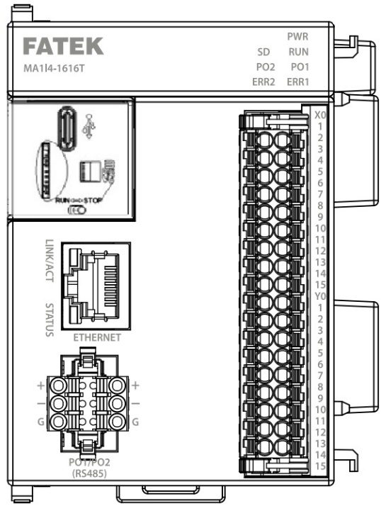
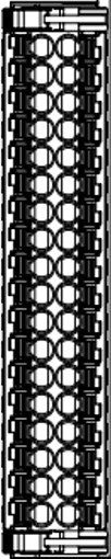
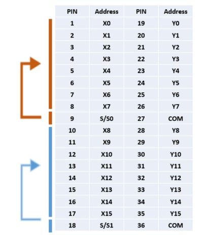
CPU Module front view and pin definition
- X0~X7 paired with S/S0,X8~X15 paired with S/S1,Y0~Y15 paired with COM
Wiring steps
1. Insert the 2x18pin press-fit European standard terminal into the DI/O slot of the CPU module (Figure 1)
2. Move the latch to the LOCK position and confirm that the European standard terminal block is fixed. (Figure 2)
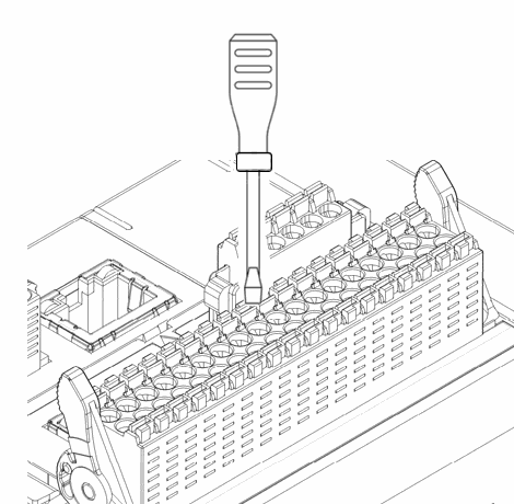
3. Use a flat-blade screwdriver tool to loosen the press, put the European standard terminal into the pressing position stably, then release the flat-blade screwdriver to complete one-contact wiring. (Figure 3)
4. After wiring is completed, the protective label (Dustproof sticker) should be removed to ensure good air circulation and heat dissipation
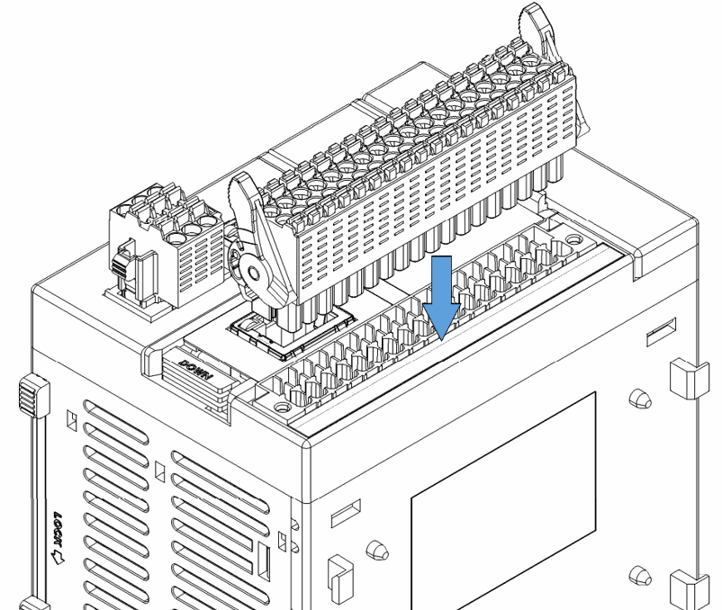 (Figure 1)
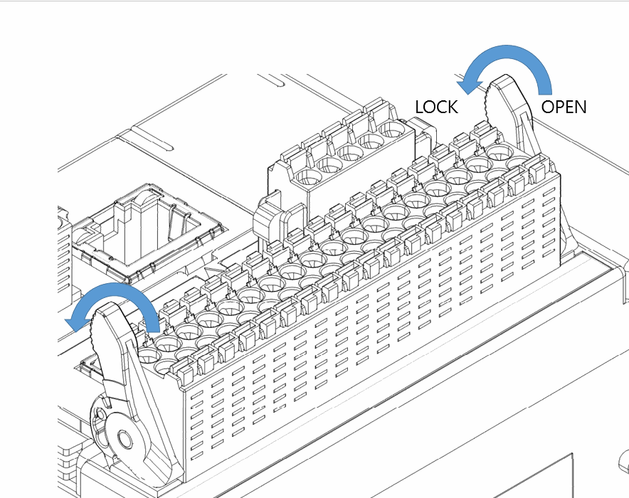 (Figure 2)
 (Figure 3)
5-7 Memory Card
The M-Series PLC support the FATEK MicroSD Card to achieve functions such as ladder diagram programs and annotations, as well as backup and writing of setting information for various modules.
5-7-1 Installing MicroSD Card
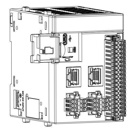 This section describes how to install the FATEK MicroSD Card on the M-Series CPU Module and relevant dismantling method.
Installing the MicroSD Card
- First, open the MPLC cover plate.
. Insert MicroSD Card into the MicroSD Card slot
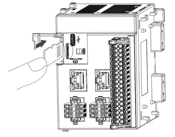 When inserting the card, place the pattern side of the MicroSD Card on the left- side with the jagged section facing upward and then insert the card straight down until hearing a click sound. After being inserted, the MicroSD Card should be fixed securely in position. If it is still under loosened status, it means that the card has not been inserted correctly. The MicroSD Card is designed with a fool-proof function. If you cannot press the card to the end, do not push it by force to avoid product damage.
3. After inserting the MicroSD Card, restore the CPU Module cover plate until hearing a click sound.
 Removing method
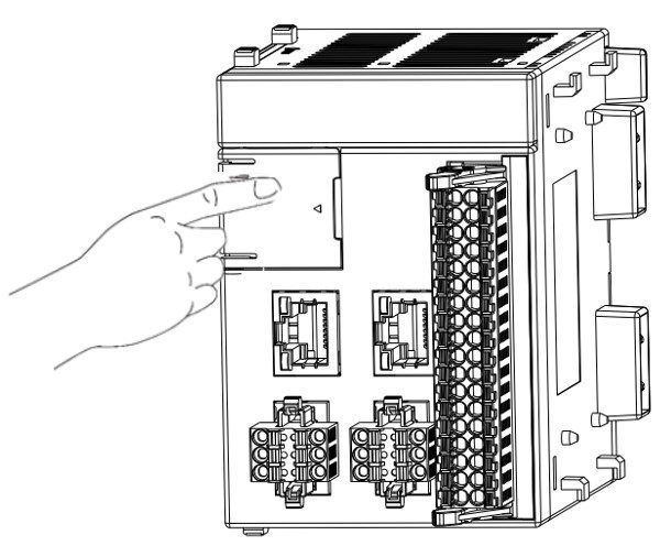
1. First, open the CPU Module cover plate.
2. Press the MicroSD Card into the MicroSD Card slot.
-
- When pressing, you may remove the MicroSD Card after hearing a click sound from the card.
3. After removing the MicroSD Card, restore the CPU Module cover plate after hearing a click sound.
※ You will be allowed to install or remove the MicroSD Card without shutting down the CPU Module, however do not remove the card during the data saving process.
5-7-2 FATEK memory card models
|
Item |
Model |
Specification |
|
1 |
MFM06 |
8GB (6GB Datalog Storage Area)*1 |
*1: Except for the 6GB Datalog in the uSD card, the others are only reserved for internal use rather than general users.
5-7-3 Supported functions list of the memory card version
|
Application |
Functions |
|
Basic |
1. User can use the SD card to update the PLC program and choose whether to protect the PLC program with a password to prevent the PLC program from being read or uploaded to the PC for backup. |
|
2. User can use the SD card to copy the machine during mass production quickly, which means after the machine tool designer completes the first machine tool, the follow-up machine can use the SD card to copy the design promptly. |
|
|
3.During the execution of the Ladder program, the user can back up the register data by command or write the backup data to a specific register address by command. |
|
|
Advanced |
User can use the SD card for data collection, and it allows the user to upload the data to the PC (or directly use the Windows PC to read the data in u-SD Card) Under envelopment |
Supported functions list
|
CPU model |
Basic application |
Advanced application |
|
ME2C3-1616◇ |
O |
O |
|
ME2C4-1616◇ |
O |
O |
|
ME2C5-1616◇ |
O |
O |
|
ME3C6-1616◇ |
O |
O |
|
MA1N0-1616◇ |
O |
X |
|
MA1N3-1616◇ |
O |
O |
|
MA1I4-1616◇ |
O |
O |
|
MS2C4-1616◇ |
O |
O |
|
MS2C5-1616◇ |
O |
O |
|
MS3C6-1616◇ |
O |
O |
|
MU2C4-1616◇ |
O |
X |
|
MU2C6-1616◇ |
O |
X |
|
MU3C2-1616◇ |
O |
X |
|
MU3C3-1616◇ |
O |
X |
|
MU3C4-1616◇ |
O |
X |
|
MU3C5-1616◇ |
O |
O |
|
MU3C6-1616◇ |
O |
O |
|
MQ2M0-1616◇ |
O |
X |
|
MQ2M1-1616◇ |
O |
X |
|
MQ2M3-1616◇ |
O |
X |
|
MQ2M6-1616◇ |
O |
O |
5-7-4 Functions of memory cards
|
Item |
Brief |
Description |
|
LED display |
The memory card is in read or write status; avoid taking it out during operation. |
■When the SD card is inserted, the SD LED indicator lights up。 |
|
Format |
Allow memory card to be used in MPLC CPU module. |
■Generally, the memory card shipped by FATEK is usable, and no additional initialization or format is required. ■If the user mistakenly deletes essential data in the memory card, resulting in the card being unable to be used in the CPU module, the user can use Uperlogic to reformat the folder and restore it to use. ■If the user re-formats the memory card through an incorrect repartition method, the memory card will become unusable and must be sent to FATEK for processing. |
|
System backup |
Same function as ROMPACK |
Same function as FBS ROMPACK; it can back up and restore PLC firmware, registers, programs, motion control data, etc.. |
|
Copy protection |
Memory card binding CPU module serial number |
■User can decide whether to bind the CPU module serial number protection from Uperlogic. ■If the user wants to use the bound SD card for different CPU modules, you must format it through Uperlogic. |
|
Firmware update |
Provide firmware update and rescue methods |
■Support PLC OS update, including rescue mode. ■Support expansion module OS update, including rescue mode. |
|
Memory Card Information |
Provide simple information about the memory card |
It can display memory card capacity, backup model, memory card model, copy protection status, system backup data availability, and system backup version. |
|
Register read/ write |
Functions such as ROMPACK read and write instructions |
Not supported yet |
|
Data collection |
Functions such as the HMI data collection instructions |
Not supported yet |
|
Log |
Support user debugging |
Not supported yet |
|
|
Attention |
1.The system protection area needs to be accessed with the Uperlogic. 2. When using the SD Card for backup, restore, or update actions, it is recommended to switch the CPU module to STOP Mode. Ensure the power supply to the CPU module is well during the backup/restore/update process; otherwise, it may lead to operation failure and potential abnormal functioning of the CPU module. |

|
|
Attention |
1. la zone de protection du système doit être accessible avec l’Uperlogic. 2. Lors de l’utilisation de la carte SD pour des actions de sauvegarde, de restauration ou de mise à jour, il est recommandé de passer le module CPU en mode STOP. Veillez à ce que l’alimentation électrique du module CPU soit correcte pendant le processus de sauvegarde/restauration/mise à jour ; dans le cas contraire, cela pourrait entraîner une panne et un fonctionnement anormal du module CPU. |

Tip: press ← → to switch chapters, Ctrl+K to search