M-Series PLC Specifications
6-1 General Specifications
|
Item |
ME,MS,MU |
MA,MQ |
|
|
Power consumption |
DC24V±20%,0.2A |
DC24V±20%,0.15A |
|
|
Grounding Requirements |
Class D grounding (type 3 grounding) |
||
|
Environmental Specifications |
Environmental temperature |
0~55℃ |
|
|
Storage humidity |
5~95% RH (non-condensation, RH-2) |
||
|
Working atmosphere |
Free from excessive conductive dust and corrosive gas. |
||
|
Storage Temperature |
-25~70℃ |
||
|
Altitude |
≤2000m |
||
|
Pollution resistance |
Degree II |
||
|
Vibration resistance |
5 to 8.4Hz Half-amplitude: 3.5mm |
||
|
Shock resistance |
10G, three times for each direction of 3 axes |
||
|
Noise resistance |
1500Vp-p,pulse width 1us |
||
|
Pressure resistance |
1500 VAC for 1 minute between power terminals and input/output terminals and between all external terminals and housing |
||
|
CPU module size |
90mm×63.4mm×90mm |
||
|
CPU module weight |
246g (excluding end module); |
236g (excluding end module); |
|
|
280g (including end module) |
270g (including end module) |
||
|
Applicable Standards |
CE,UL* |
||
CPU General Specifications
*Please note when placing an order.
6-2 CPU Specifications
Specifications for advanced motion and general motion PLC model
|
Specification |
ME3C6 |
ME2C5 |
ME2C4 |
ME2C3 |
MS3C6 |
MS2C5 |
MS2C4 |
|||
|
Programming language |
LD / ST / FB / STP / MotionFlow |
|||||||||
|
Instruction execution speed |
LD Instruction |
0.0008 uS/ LD (0.8nS/LD) |
||||||||
|
MOV Instruction |
0.0075 uS/ LD (7.5nS / MOV) |
|||||||||
|
Maximum I/O |
DIO |
2048 |
2048 |
1024 |
1024 |
2048 |
2048 |
1024 |
||
|
AIO |
256 |
256 |
128 |
128 |
256 |
256 |
128 |
|||
|
Maximum Expansion Modules |
Local I/O + High-speed |
64 units (with the use of I/O Bus Extension module) |
||||||||
|
High-speed Expansion |
6 units (need to be installed between CPU and Local I/O module) |
|||||||||
|
Advanced Expansion |
● |
● |
● |
● |
● |
● |
● |
|||
|
Plug-in Expansion |
- |
- |
- |
- |
- |
- |
- |
|||
|
Program Memory |
PLC |
80KB |
80KB |
80KB |
80KB |
80KB |
80KB |
80KB |
||
|
Motion |
3 MB |
1.5 MB |
1.1 MB |
742 KB |
3 MB |
1.5 MB |
1.1 MB |
|||
|
Memory card*5 Dedicated Industrial Grade Micro-SD Card |
Project Backup and Restore |
Support project and OS update with memory card |
||||||||
|
Register Data Backup and Restore |
● |
● |
● |
● |
● |
● |
● |
|||
|
Built-in digital input and output |
Input 16 points 、 Output 16 points |
|||||||||
|
Built-in analog input |
2ch 12bits |
|||||||||
|
Built-in analog output |
Optional selection (PWMDA x1 only in Y0) |
|||||||||
|
Communication Interface |
ETHERNET |
Interface |
1 Port 10/100 Base-T |
|||||||
|
Modbus / User-Defined |
Master/Slave |
|||||||||
|
Connections |
16 |
|||||||||
|
EtherCAT |
1 Port |
|||||||||
|
RS-485 |
2 ports ,Support Master/Slave ,Communication speed 4.8K~921.6Kbps |
|||||||||
|
Maximum serial ports |
14 (2 Built-in + 12 Expansion) |
|||||||||
|
USB |
1 port ,USB Type C (USB 2.0) |
|||||||||
|
IoT expansion*4 |
MQTT , FATEK iMonitor / iAccess |
|||||||||
|
Motion Control |
Number of control axes |
24 |
22 |
18 |
13 |
24 |
22 |
18 |
||
|
Pulse |
Axes |
8 |
8 |
8 |
8 |
8 |
8 |
8 |
||
|
Output frequency |
200KHz |
200KHz |
200KHz |
200KHz |
200KHz |
200KHz |
200KHz |
|||
|
Pulse output mode |
3 Modes(U/D、P/R、A/B) |
|||||||||
|
Linear Interpolation |
● |
● |
● |
● |
● |
● |
● |
|||
|
Circular Interpolation |
● |
● |
● |
● |
● |
● |
● |
|||
|
ICF/ICA*2 |
● |
● |
● |
● |
● |
● |
● |
|||
|
EtherCAT |
Number of axes (A+B+C) |
16 |
14 |
10 |
5 |
16 |
14 |
10 |
||
|
Real/Virtual axes(A) |
16 |
12 |
8 |
4 |
16 |
12 |
8 |
|||
|
Additional Virtual axes(B) |
0 |
2 |
2 |
1 |
0 |
2 |
2 |
|||
|
Additional SAPC*1 axes on Eth/EC port(C) |
- |
- |
- |
- |
- |
- |
- |
|||
|
Specification |
ME3C6 |
ME2C5 |
ME2C4 |
ME2C3 |
MS3C6 |
MS2C5 |
MS2C4 |
||
|
Motion Control |
EtherCAT |
Linear Interpolation |
● |
● |
● |
● |
● |
● |
● |
|
Circular Interpolation |
● |
● |
● |
● |
● |
● |
● |
||
|
ICF/ICA*2 |
● |
● |
● |
● |
● |
● |
● |
||
|
3D Circular/Helical Interpolation |
● |
● |
● |
● |
- |
- |
- |
||
|
E-cam(Fly-saw/Rotary-cut) |
16 |
12 |
8 |
4 |
3 |
3 |
2 |
||
|
High-speed counter (200KHz) *3 |
16 points (8 channel) |
16 points (8 channel) |
|||||||
|
High-speed Pulse output |
16 points(8 axes) |
16 points(8 axes) |
|||||||
|
High-speed timer 0.1mS |
1 (16-bit) , 4 (32-bit) |
||||||||
|
Built-in RTC |
sec,min,hour,day,month,year,week |
||||||||
|
Data retentive |
Program and Data |
Non-volatile memory (no battery required) |
|||||||
|
Calendar |
Battery |
||||||||
|
Specification |
MU3C6 |
MU3C5 |
MU3C4 |
MU3C3 |
MU3C2*7 |
MU2C6 |
MU2C4 |
||
|
Programming language |
LD / ST / FB / STP / MotionFlow |
||||||||
|
Instruction execution speed |
LD Instruction |
0.0008 uS/ LD (0.8nS/LD) |
|||||||
|
MOV Instruction |
0.0075 uS/ LD (7.5nS / MOV) |
||||||||
|
Maximum I/O |
DIO |
512 |
512 |
512 |
512 |
512 |
512 |
512 |
|
|
AIO |
128 |
128 |
128 |
128 |
128 |
128 |
128 |
||
|
Maximum Expansion Modules |
Local I/O + High-speed |
64 units (with the use of I/O Bus Extension module) |
|||||||
|
High-speed Expansion |
- |
- |
- |
- |
- |
- |
- |
||
|
Advanced Expansion |
- |
- |
- |
- |
- |
- |
- |
||
|
Plug-in Expansion |
- |
- |
- |
- |
- |
- |
- |
||
|
Program Memory |
PLC |
80KB |
80KB |
80KB |
80KB |
80KB |
80KB |
80KB |
|
|
Motion |
1.5 MB |
1.5 MB |
1.5 MB |
1.5 MB |
1.5 MB |
1.5 MB |
1.5 MB |
||
|
Memory card*5 Dedicated Industrial Grade Micro-SD Card |
Project Backup and Restore |
Support project and OS update with memory card |
|||||||
|
Register Data Backup and Restore |
● |
● |
● |
● |
● |
● |
● |
||
|
Built-in digital input and output |
Input 16 points 、 Output 16 points |
||||||||
|
Built-in analog input |
2ch 12bits |
||||||||
|
Built-in analog output |
Optional selection (PWMDA x1 only in Y0) |
||||||||
|
Communication Interface |
ETHERNET |
Interface |
1 Port 10/100 Base-T |
||||||
|
Modbus / User-Defined |
Master/Slave |
||||||||
|
Connections |
16 |
||||||||
|
EtherCAT |
1 Port |
||||||||
|
RS-485 |
2 ports ,Support Master/Slave ,Communication speed 4.8K~921.6Kbps |
||||||||
|
Maximum serial ports |
2 Built-in |
||||||||
|
USB |
1 port ,USB Type C (USB 2.0) |
||||||||
|
IoT expansion*4 |
MQTT , FATEK iMonitor / iAccess |
||||||||
|
Specification |
MU3C6 |
MU3C5 |
MU3C4 |
MU3C3 |
MU3C2*7 |
MU2C6 |
MU2C4 |
|||
|
Motion Control |
Number of control axes |
20 |
17 |
9 |
9 |
7 |
18 |
10 |
||
|
Pulse |
Axes |
4 |
4 |
2 |
2 |
2 |
2 |
2 |
||
|
Output frequency |
200KHz |
200KHz |
200KHz |
200KHz |
200KHz |
200KHz |
200KHz |
|||
|
Pulse output mode |
1 Modes(P/R) |
|||||||||
|
Linear Interpolation |
● |
● |
● |
● |
● |
● |
● |
|||
|
Circular Interpolation |
● |
● |
● |
● |
● |
● |
● |
|||
|
ICF/ICA*2 |
● |
● |
● |
● |
● |
● |
● |
|||
|
EtherCAT |
Number of axes (A+B+C) |
16 |
13 |
7 |
7 |
5 |
16 |
8 |
||
|
Real/Virtual axes(A) |
16 |
12 |
6 |
6 |
4 |
16 |
8 |
|||
|
Additional Virtual axes(B) |
– |
1 |
1 |
1 |
1 |
- |
- |
|||
|
Additional SAPC*1 axes on Eth/EC port(C) |
– |
– |
- |
- |
- |
- |
- |
|||
|
Linear Interpolation |
● |
● |
● |
● |
● |
● |
● |
|||
|
Circular Interpolation |
● |
● |
● |
● |
● |
● |
● |
|||
|
ICF/ICA*2 |
● |
● |
● |
● |
● |
- |
- |
|||
|
3D Circular/Helical Interpolation |
– |
– |
- |
- |
- |
- |
- |
|||
|
E-cam(Fly-saw/Rotary-cut) |
6 |
4 |
4 |
3 |
2 |
- |
- |
|||
|
High-speed counter (200KHz) *3 |
6 points (3 channel) *3 |
4 points (2 channel) |
||||||||
|
High-speed counter (10KHz) |
10 points (5 channel) |
12 points (6 channel) |
||||||||
|
High-speed Pulse output |
8 points(4 axes) |
4 points(2 axes) |
||||||||
|
High-speed timer 0.1mS |
1 (16-bit) , 4 (32-bit) |
|||||||||
|
Built-in RTC |
sec,min,hour,day,month,year,week |
|||||||||
|
Data retentive |
Program and Data |
Non-volatile memory (no battery required) |
||||||||
|
Calendar |
Battery |
|||||||||
Specifications for advanced and compact PLC models.
|
Specification |
MA1I4 |
MA1N3 |
MA1N0 |
MQ2M6 |
MQ2M3 |
MQ2M1 |
MQ2M0 |
|||
|
Programming language |
LD / ST / FB / STP / MotionFlow |
|||||||||
|
Instruction execution speed |
LD Instruction |
0.0008 uS/ LD (0.8nS/LD) |
||||||||
|
MOV Instruction |
0.0075 uS/ LD (7.5nS / MOV) |
|||||||||
|
Maximum I/O |
DIO |
2048 |
1024 |
1024 |
512 |
512 |
512 |
512 |
||
|
AIO |
256 |
128 |
128 |
128 |
128 |
128 |
128 |
|||
|
Maximum Expansion Modules |
Local I/O + High-speed |
64 units (with the use of I/O Bus Extension module) |
||||||||
|
High-speed Expansion |
6 units (need to be installed between CPU and Local I/O module) |
- |
- |
- |
- |
|||||
|
Advanced Expansion |
● |
● |
● |
- |
- |
- |
- |
|||
|
Plug-in Expansion |
- |
- |
- |
2 Sets |
||||||
|
Program Memory |
PLC |
80KB |
80KB |
80KB |
80KB |
80KB |
80KB |
80KB |
||
|
Motion |
- |
- |
- |
- |
- |
- |
- |
|||
|
Memory card*5 Dedicated Industrial Grade Micro-SD Card |
Project Backup and Restore |
Support project and OS update with memory card |
||||||||
|
Register Data Backup and Restore |
● |
● |
● |
● |
● |
● |
● |
|||
|
Specification |
MA1I4 |
MA1N3 |
MA1N0 |
MQ2M6 |
MQ2M3 |
MQ2M1 |
MQ2M0 |
|||
|
Built-in digital input and output |
Input 16 points 、 Output 16 points |
|||||||||
|
Built-in analog input |
- |
- |
- |
- |
- |
- |
- |
|||
|
Built-in analog output |
Optional selection (PWMDA x1 only in Y0) |
|||||||||
|
Communication Interface |
ETHERNET |
Interface |
1 Port 10/100 Base-T |
|||||||
|
Modbus / User-Defined |
Master/Slave |
|||||||||
|
Connections |
16 |
|||||||||
|
EtherCAT |
1 Port (Eth/EC port shared with Ethernet*1) |
- |
1 Port (Eth/EC port shared with Ethernet) |
- |
- |
- |
||||
|
RS-485 |
2 ports ,Support Master/Slave ,Communication speed 4.8K~921.6Kbps |
|||||||||
|
Maximum serial ports |
14 (2 Built-in + 12 Expansion) |
4 (2 Built-in + 2 Plug-in) |
||||||||
|
USB |
1 port ,USB Type C (USB 2.0) |
|||||||||
|
IoT expansion*4 |
MQTT , FATEK iMonitor / iAccess |
|||||||||
|
Motion Control |
Number of control axes |
24 axes |
12 axes |
– |
20 axes |
4 axes |
2 axes |
- |
||
|
Pulse |
Axes |
8 axes |
4 axes |
– |
4 axes Can expand up to 8 axes |
4 axes Can expand up to 8 axes |
2 axes Can expand up to 6 axes |
- |
||
|
Output frequency |
200KHz |
200KHz |
– |
200KHz |
200KHz |
200KHz |
– |
|||
|
Pulse output mode |
3 Modes (U/D、P/R、A/B) |
|||||||||
|
Linear Interpolation |
● |
● |
– |
● |
● |
● |
– |
|||
|
Circular Interpolation |
● |
– |
– |
● |
– |
– |
– |
|||
|
ICF/ICA*2 |
● |
● |
– |
● |
● |
● |
– |
|||
|
EtherCAT |
Number of axes (A+B+C) |
16 |
8 |
– |
16 |
– |
– |
– |
||
|
Real/Virtual axes(A) |
– |
– |
– |
– |
– |
– |
– |
|||
|
Additional Virtual axes(B) |
– |
– |
– |
– |
– |
– |
– |
|||
|
Additional SAPC*1 axes on Eth/EC port(C) |
16*6 |
8*6 |
– |
16 |
– |
– |
– |
|||
|
Linear Interpolation |
- |
- |
- |
- |
- |
- |
- |
|||
|
Circular Interpolation |
- |
- |
- |
- |
- |
- |
- |
|||
|
ICF/ICA*2 |
- |
- |
- |
- |
- |
- |
- |
|||
|
3D Circular/Helical Interpolation |
- |
- |
- |
- |
- |
- |
- |
|||
|
E-cam(Fly-saw/Rotary-cut) |
- |
- |
- |
- |
- |
- |
- |
|||
|
High-speed counter (200KHz) *3 |
8 points (4 channels) |
- |
8 points (4 channels) Can expand up to 8 channels |
4 points (2 channel) Can expand up to 6 channel |
- |
|||||
|
High-speed Pulse output |
16 points (8 axes) |
8 points (4 axes) |
- |
8 points (4 axes) Can expand up to 8 axes |
4 points (2 axes) Can expand up to 6 axes |
- |
||||
|
High-speed timer 0.1mS |
1 (16-bit) , 4 (32-bit) |
|||||||||
|
Built-in RTC |
sec,min,hour,day,month,year,week |
- (Can Expandable through by MB-RTC) |
||||||||
|
Data retentive |
Program and Data |
Non-volatile memory (no battery required) |
||||||||
|
Calendar |
Battery |
|||||||||
◇:T — Transistor SINK(NPN) output;
J — Transistor SOURCE (PNP) output
*1 : SAPC (single axis positioning control) . Eth/EC ports on MA/MQ some models can be switched to support Ethernet/EtherCAT.
*2 : ICF (interrupt constant feed) , ICA(interrupt constant angle)
*3 : ME/MS/MU models, half of the available channels are reserved for Motion control
*4 : CPU built-in support for MQTT and iMonitor functions, while iAccess will be supported through advanced expansion (planned support in 2025). iMonitor and iAccess services must be activated using a license key
*5 : Only supports the MFM06 dedicated SD memory card (planned for support in 2026)
*6 : Expected future support
*7 : MU3C2 consolidates the majority of functions from MS2C3 / MS1C2 / MS1C1
6-3 CPU advanced specifications
|
Specification |
ME3C6 |
ME2C5 |
ME2C4 |
ME2C3 |
MS3C6 |
MS2C5 |
MS2C4 |
|
|
HSPWM |
Points |
8 axis |
||||||
|
Output frequency |
72Hz~18.432KHz (Resolution is 0.1﹪) /720Hz~184.3KHz(Resolution is 1﹪) |
|||||||
|
Interrupt control |
External input interrupt |
32 (Positive/negative edge of 16-point input) *4 |
||||||
|
Internal timed interrupt |
0.1 ms : 4 groups / 1 ms: 4 groups / 10 ms: 4 groups |
|||||||
|
High-speed Counter interrupt*3 |
8 groups*3 |
|||||||
|
Capture input |
Points |
Max 8 Point |
||||||
|
Capture pulse width |
>10μs(high speed input) |
|||||||
|
Digital filtering (Digital Filter) |
X0~X7 (frequency : 28KHz~1.8MH,Time constant : 3~15ms ) |
|||||||
|
Input contact (DI) |
X |
1024 |
1024 |
512 |
512 |
1024 |
1024 |
512 |
|
Output relay (DO) |
Y |
1024 |
1024 |
512 |
512 |
1024 |
1024 |
512 |
|
Temporary relay |
TR |
32 |
||||||
|
Internal relay |
M |
25600 |
||||||
|
Stepper relay |
S |
3104 |
||||||
|
Timer Status Contact |
T |
1024 |
||||||
|
Counter status contact |
C |
16 bit : 1024, 32 bit : 256 |
||||||
|
Timer |
TMR |
1024 |
||||||
|
Counter |
CTR |
16 bit : 1024, 32 bit : 256 |
||||||
|
Data register |
R |
R:34768 , D:8000 |
||||||
|
ROR |
4096 |
|||||||
|
F |
65536 |
|||||||
|
Input/ Output register |
AI+AO |
256 |
256 |
128 |
128 |
256 |
256 |
128 |
|
System special register |
SR |
7944(all) |
||||||
|
Pointer register |
XR |
12(V,Z,P0~P9(10)) |
||||||
*3 : ME/MS/MU models, half of the available channels are reserved for Motion control
*4 : 16 of the ME/MS/MU models are used for Motion control
|
Specification |
MU3C6 |
MU3C5 |
MU3C4 |
MU3C3 |
MU3C2*7 |
MU2C6 |
MU2C4 |
|
|
HSPWM |
Points |
4 axis |
2 axis |
|||||
|
Output frequency |
72Hz~18.432KHz (Resolution is 0.1﹪) /720Hz~184.3KHz(Resolution is 1﹪) |
|||||||
|
Interrupt control |
External input interrupt |
32 (Positive/negative edge of 16-point input) *4 |
||||||
|
Internal timed interrupt |
0.1 ms : 4 groups / 1 ms: 4 groups / 10 ms: 4 groups |
|||||||
|
High-speed Counter interrupt*3 |
3 groups |
2 groups*3 |
||||||
|
Capture input |
Points |
Max 8 Point |
||||||
|
Capture pulse width |
>10μs(high speed input) |
|||||||
|
Digital filtering (Digital Filter) |
X0~X7 (frequency : 28KHz~1.8MH,Time constant : 3~15ms ) |
|||||||
|
Input contact (DI) |
X |
256 |
256 |
256 |
256 |
256 |
256 |
256 |
|
Output relay (DO) |
Y |
256 |
256 |
256 |
256 |
256 |
256 |
256 |
|
Temporary relay |
TR |
32 |
||||||
|
Internal relay |
M |
25600 |
||||||
|
Stepper relay |
S |
3104 |
||||||
|
Timer Status Contact |
T |
1024 |
||||||
|
Counter status contact |
C |
16 bit : 1024, 32 bit : 256 |
||||||
|
Timer |
TMR |
1024 |
||||||
|
Counter |
CTR |
16 bit : 1024, 32 bit : 256 |
||||||
|
Data register |
R |
R:34768 , D:8000 |
||||||
|
ROR |
4096 |
|||||||
|
F |
65536 |
|||||||
|
Input/ Output register |
AI+AO |
256 |
256 |
128 |
128 |
256 |
256 |
128 |
|
System special register |
SR |
7944(all) |
||||||
|
Pointer register |
XR |
12(V,Z,P0~P9(10)) |
||||||
|
Specification |
MA1I4 |
MA1N3 |
MA1N0 |
MQ2M6 |
MQ2M3 |
MQ2M1 |
MQ2M0 |
|
|
HSPWM |
Points |
8 axis |
4 axis |
0 axis |
4 axes (Can expand up to 8 axes) |
2 axes (Can expand up to 6 axes) |
0 axis |
|
|
Output frequency |
72Hz~18.432KHz (Resolution is 0.1﹪) /720Hz~184.3KHz(Resolution is 1﹪) |
|||||||
|
Interrupt control |
External input interrupt |
32 (Positive/negative edge of 16-point input) *4 |
||||||
|
Internal timed interrupt |
0.1 ms : 4 groups / 1 ms: 4 groups / 10 ms: 4 groups |
|||||||
|
High-speed Counter interrupt*3 |
4 groups |
0 groups |
4 groups (Can expand up to 8 groups) |
2 groups (Can expand up to 6 groups) |
0 groups |
|||
|
Capture input |
Points |
Max 8 Point |
||||||
|
Capture pulse width |
>10μs(high speed input) |
|||||||
|
Digital filtering (Digital Filter) |
X0~X15 (frequency : 28KHz~1.8MH,Time constant : 3~15ms ) |
|||||||
|
Input contact (DI) |
X |
1024 |
512 |
512 |
256 |
256 |
256 |
256 |
|
Output relay (DO) |
Y |
1024 |
512 |
512 |
256 |
256 |
256 |
256 |
|
Temporary relay |
TR |
32 |
||||||
|
Internal relay |
M |
25600 |
||||||
|
Stepper relay |
S |
3104 |
||||||
|
Timer Status Contact |
T |
1024 |
||||||
|
Counter status contact |
C |
16 bit:1024, 32 bit:256 |
||||||
|
Timer |
TMR |
1024 |
||||||
|
Counter |
CTR |
16 bit:1024, 32 bit:256 |
||||||
|
Data register |
R |
R:34768, D:8000 |
||||||
|
ROR |
4096 |
|||||||
|
F |
65536 |
|||||||
|
Input/ Output register |
AI+AO |
256 |
128 |
128 |
128 |
128 |
128 |
128 |
|
System special register |
SR |
7944(all) |
||||||
|
Pointer register |
XR |
12(V,Z,P0~P9(10)) |
||||||
6-4 Digital Input (DI) Circuit
|
Item |
Specifications |
|
|
Input Points |
16 points (8 points/1 common point) |
|
|
Input Type |
24VDC Single-end input |
|
|
Maximum input frequency |
200KHz |
|
|
Input Signal Voltage |
24VDC±10% |
|
|
Threshold |
ON Current |
>4mA |
|
OFF Current |
<2mA |
|
|
Maximum Input Current |
6mA(DC24V) |
|
|
Input indication |
Displayed by LED: light when “ON”, dark when “OFF” |
|
|
Isolation Type |
optical isolation,500VAC,1 minute |
|
|
SINK /SOURCE Wiring |
Via variation of internal common terminal S/S and external common wiring |
|
|
Noise Filtering Time |
DHF(0 ~ 15ms)+AHF(0.47μs) DHF:Digital Hardware Filter, AHF:Analog Hardware Filter |
|
|
External connection |
36 pin Push-in terminal blocks |
|
DI specification of CPU module
6-4-1 24VDC Single-End Input Circuit and Wiring for SINK/SOURCE Input
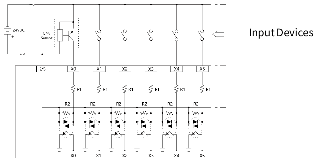
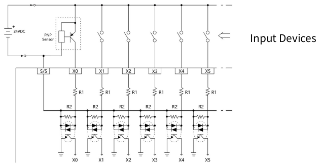
The 24VDC single-end digital input circuits of M Series PLC are available for high, medium and low speed. They all have the similar circuit structures but with different response speeds. To save input terminals, the circuit of single-end input is implemented by connecting one end of all input points (photo coupler) inside the PLC to the same internal common point labeled as S/S. The other end of each input circuit is connected to corresponding terminals such as X0, X1, X2, etc. The S/S common terminal and N single-end inputs comprise of N digital inputs (i.e., only N+1 terminals are used for N terminals). Therefore, we call this type of input structure the single-end input. The user also needs to do the same thing when making the connection of external digital input devices. Namely, the one end of all input devices (e.g., buttons, switches) are connected together and called the external common wire, while the other ends of input circuits are connected to the input terminals X0, X1, X2, etc., of PLC. Then finish it by connecting the external common wiring and internal common terminal S/S to the positive/negative terminals of the 24VDC power. When connect the internal common terminal S/S to 24V+(positive) and the external common wire to 24V- (negative), then the circuit serve as SINK input. On the contrary, while exchange the wiring of the above internal and external common will serve as a SOURCE input. The above wiring schemes can illustrate below:
Wiring of single-end common SINK input
Wiring of single-end common SOURCE input
6-5 Digital Output (DO) Circuit
The digital output of MPLC is a transistor. However, due to the polarity relationship of the transistor, after single-ended common output is adopted, the polarities of SINK and SOURCE are opposite (the output common point COM of SINK must be connected to the negative terminal of the DC power supply, and the output common point COM of SRCE must be connected to the negative terminal of the DC power supply. to the positive end of the DC power supply), so the MPLC transistor output model is divided into two types: SINK output or SRCE output.
|
Warning |
|
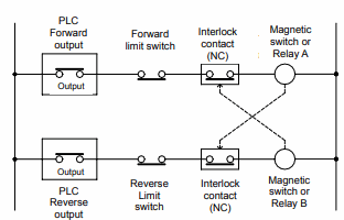
1. The output of M series PLC has no over-current protection. In the application of output circuit with safety consideration, users need to install over-current or short-circuit protection devices, such as fuses, in the external circuit. 2. In applications where it is dangerous to start at the same time of forward and reverse rotation, in addition to the interlock in the PLC internal program, an interlock circuit needs to be installed outside the PLC, as shown in the example below:
Interlock circuit wiring diagram |
|
Avertissement |
|
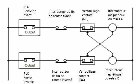
1. La sortie de l’automate de la série M n’a pas de protection contre les surintensités. Dans l’application du circuit de sortie avec des considérations de sécurité, les utilisateurs doivent installer des dispositifs de protection contre les surintensités ou les courts-circuits, tels que des fusibles, dans le circuit externe. 2. Dans les applications où il est dangereux de démarrer en même temps la rotation avant et la rotation arrière, en plus du verrouillage dans le programme interne de l’automate, un circuit de verrouillage doit être installé à l’extérieur de l’automate, comme le montre l’exemple ci-dessous : Schéma de câblage du circuit de verrouillage |
6-5-1 Digital Output Circuit Specifications
|
Item |
Specifications |
|
|
Output Points |
16 |
|
|
Output Mode |
Single-End Transistor Output; T model: SINK(NPN), J model: SOURCE(PNP) |
|
|
Maximum output frequency |
200kHz |
|
|
Working Voltage |
5~30VDC |
|
|
Maximum Load Current Resistive |
0.1A |
|
|
Maximum Voltage Drop |
0.6V |
|
|
Leakage Current |
<0.1mA/30VDC |
|
|
Maximum Output Delay Time |
ON → OFF |
2μS |
|
OFF → ON |
2μS |
|
|
Isolation method |
Optical Isolation, 500VAC, 1 minute |
|
|
output status indication |
Displayed by LED : Light when "ON", Dark when "OFF" |
|
|
SINK/SOURCE output type |
Choose SINK/SOURCE by models and non-exchangeable |
|
|
External connection |
36 pin Push-in terminal blocks |
|
DO specification of CPU module
6-5-2 Structure and Wiring of Single-End Transistor SINK and SOURCE Output Circuit
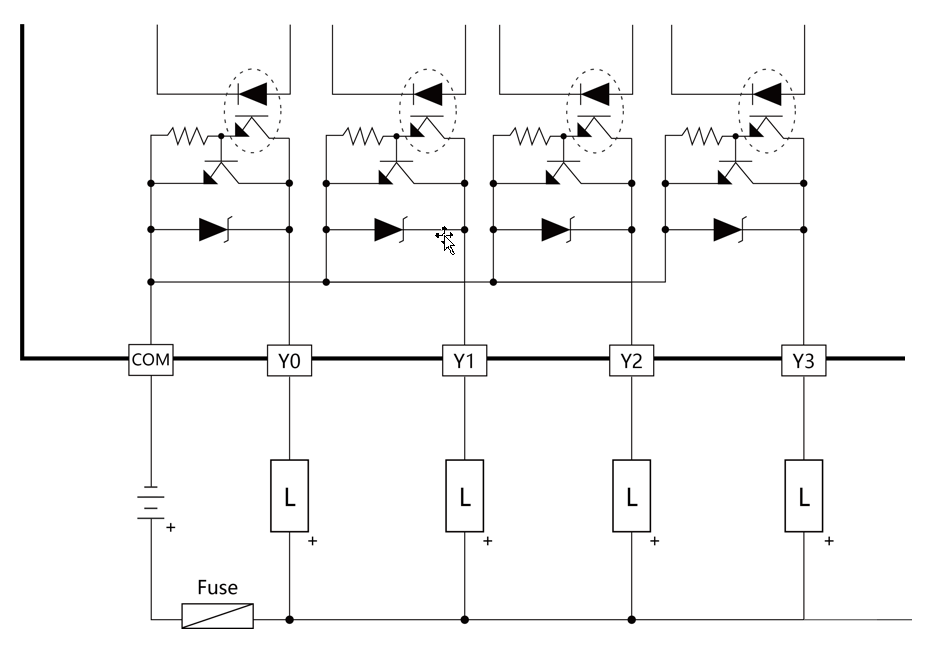
Transistor Single-End SINK Output
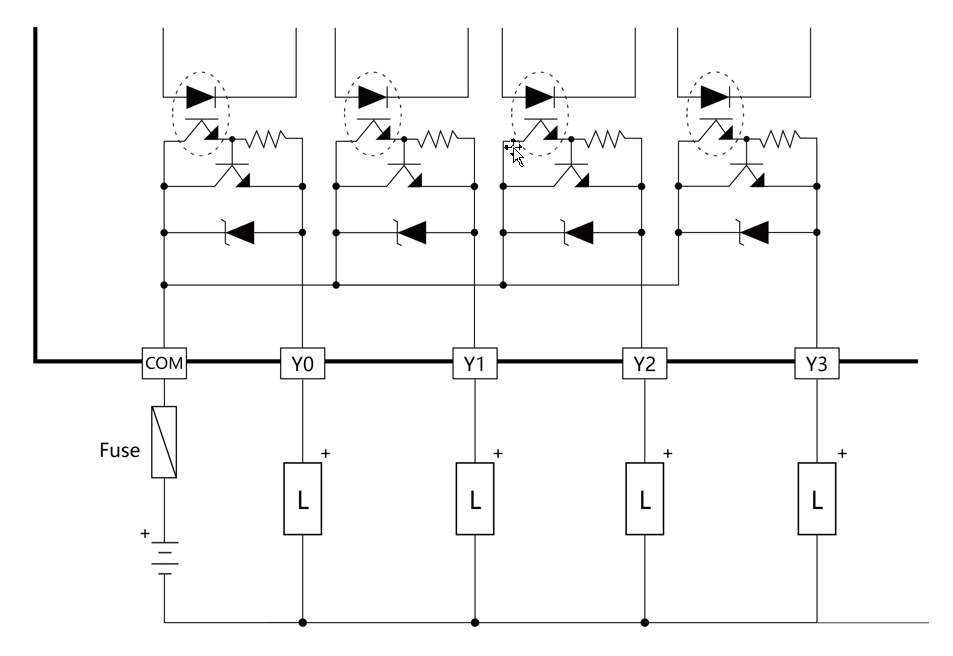
Transistor Single-End SOURCE Output
The above figure also takes the output blocks with 2-current and 4-current structures as an example, respectively explaining the difference in the structure of the SINK output and SOURCE output circuits and their wiring methods (the structure and wiring of the 8-common output block are also the same, only the points numbers are different). The SINK output and SOURCE output of MPLC Transistor Single-End concurrent are different models. Users must pay attention to the SINK output model or the SOURCE output model when ordering.
6-5-3 Protection of Transistor Output and Noise Suppression
The transistor output in M Series PLC already includes Zener diode for counter-electromotive force, which is sufficient for low power inductive load and medium frequency of ON/OFF application. In conditions of high power or frequent ON/OFF, please construct another suppression circuit to lower noise interference and prevent voltage from exceeding the limit or overheating that may damage the transistor output circuit.
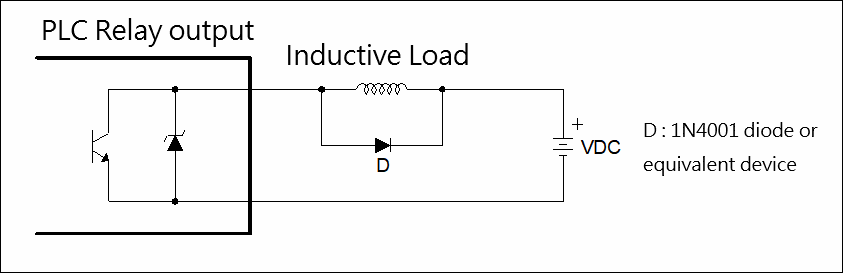
Suppress by a diode (for low power)
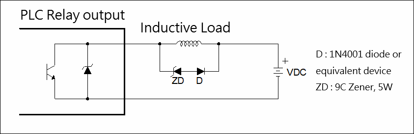
Suppress by a diode + Zener (high power and frequent ON/OFF)
6-6 Analog input specifications
|
Item |
Specification |
|||
|
Input points |
2 channels |
|||
|
Analog input characteristics and resolution |
Voltage |
Analog input range |
Value |
Resolution |
|
0~10V |
0~4096 |
2.44mV |
||
|
Current |
Analog input range |
Value |
Resolution |
|
|
0~20mA |
0~4096 |
4.88uA |
||
|
Conversion percision |
Voltage |
±1% (25°C±5 °C ) |
||
|
Current |
±1% (25° C±5°C) |
|||
|
Conversion speed |
Conversion once for each scan |
|||
|
Input resistance |
Voltage : 76KΩ Current : 165Ω |
|||
|
Hardware maximum input |
Voltage: 0 ~ 15V Current: 0 ~ 30mA |
|||
|
External connection |
2X3 pins push-in terminal blocks |
|||
6-7 Dimensions of CPU Module
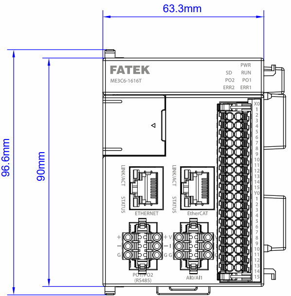
The front dimension of CPU module(MS,ME)
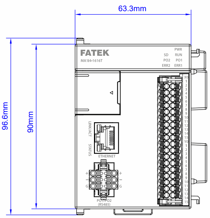
The front dimension of CPU module(MA)
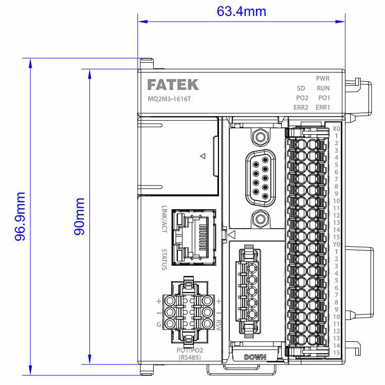
The front dimension of CPU module(MQ)
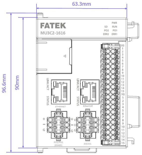
The front dimension of CPU module(MU)
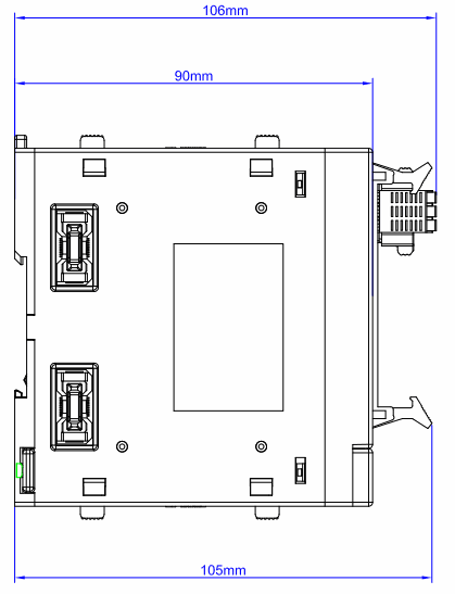
The side dimension of CPU module(MA,MS,ME)
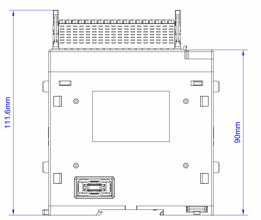
The side dimension of CPU module(MQ,MU)
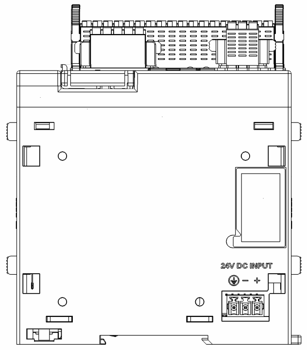
The side dimension of CPU module(MQ, MA, MS, ME,MU)
※The module dimension of Compact, Advanced,and General/ Advanced motion contral types are exactly same.
Tip: press ← → to switch chapters, Ctrl+K to search