Hardware Installation and Wiring
|
Caution |
|
|
– The installation that the safety of any system incorporating the equipment is the responsibility of the assembler of the system. L’installation ainsi que la sécurité de tout système intégrant l’équipement relèvent de la responsabilité de l’assembleur du système. |
|
|
– If the equipment is used in a manner not specified by the manufacturer, the protection provided by the equipment may be impaired. Si l’équipement est utilisé d’une manière non spécifiée par le fabricant, la protection fournie par l’équipement peut être altérée. |
|


This section describes the assembly method of the power module and CPU module as well as the fixed guide rail installation method and the wiring method.
For detailed installation and wiring method of other expansion modules, please refer to “Expansion Module Operating Manual.”
10-1 Installation
When connecting the module, it shall be executed after the power is disconnected and it is also required to follow safety instructions.
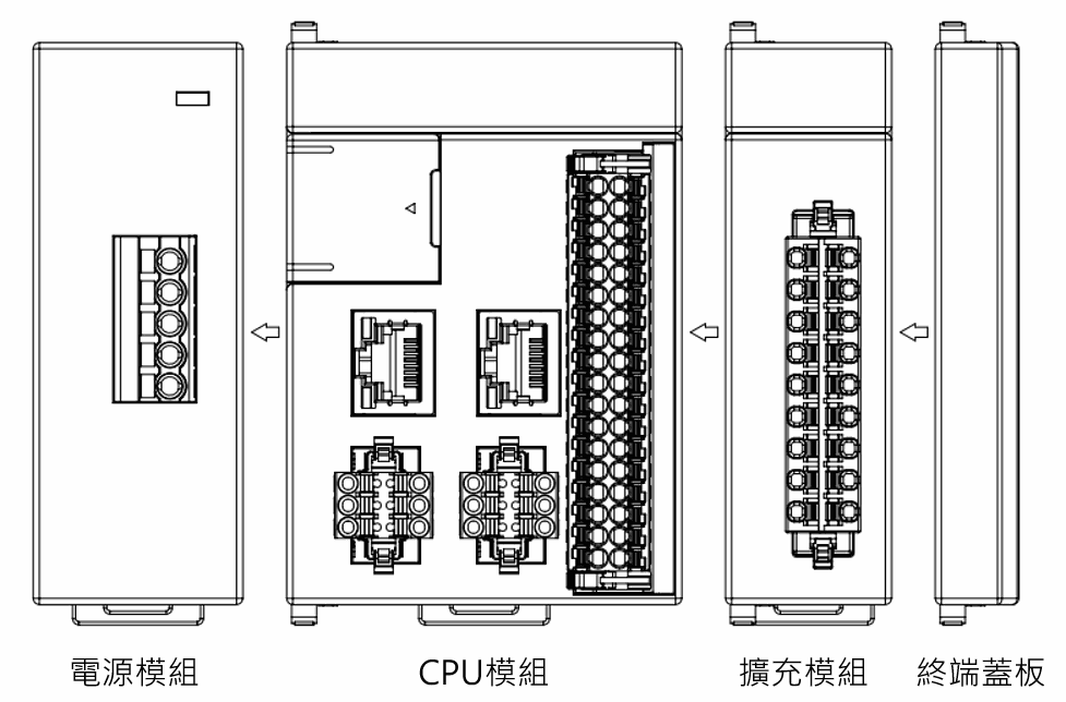
Power Module CPU Module Expansion End
Module Module
|
Precaution |
|
The final module on the rightmost end should be equipped with a termination cover plate during the installation process. |
|
Précaution |
|
Le dernier module à l’extrémité droite doit être équipé d’une plaque d’obturation lors de l’installation. |
- Installation position
Installation direction: When installed in the panel, the front-side panel of the CPU Module should
face forward.
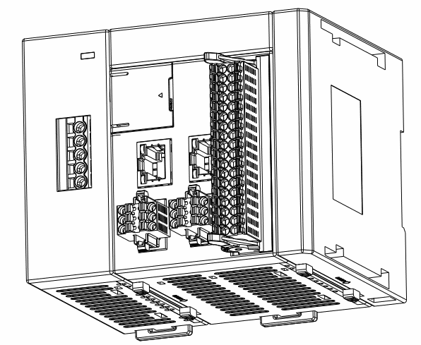
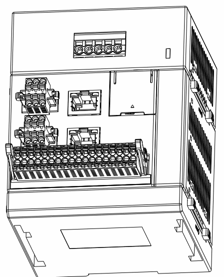
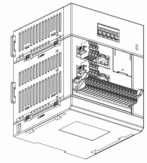
- Separate with peripheral environment
The M-Series PLC Module is designed with natural air convection to dissipate the heat. For this reason, the upper side and the bottom side of the PLC must also be reserved with a gap wider than 50mm for easier heat dissipation, per the figure below:
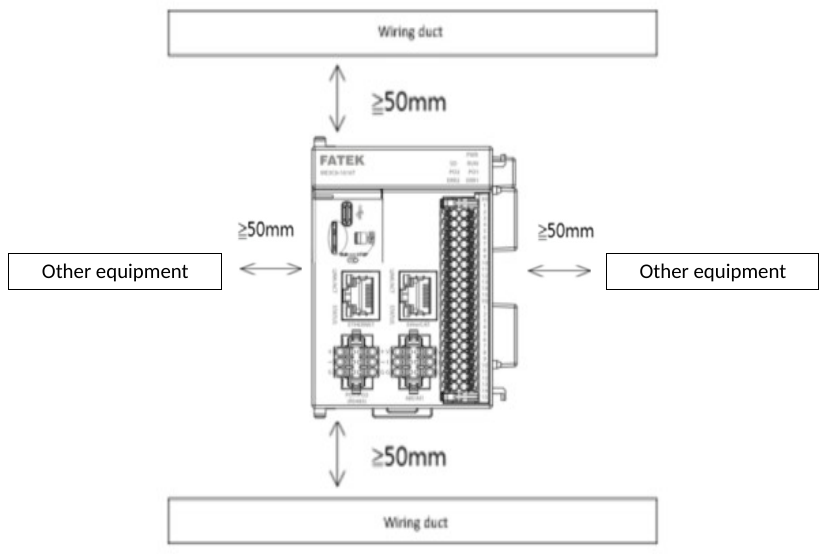 When exceeding the working environment temperature, please use the forced cooling method, or widen the spacing with peripheral environment or improve the ventilation effect to reduce the temperature. When using the expansion module, it is also required to consider the heat effect by widening the space between upper and lower modules for over 50mm.
10-1-1 Module assembly
Regarding the connection between the M-Series PLC Module and other modules, the assembly of the M-Series CPU Module and the power module will be used as the example for explanation as below.
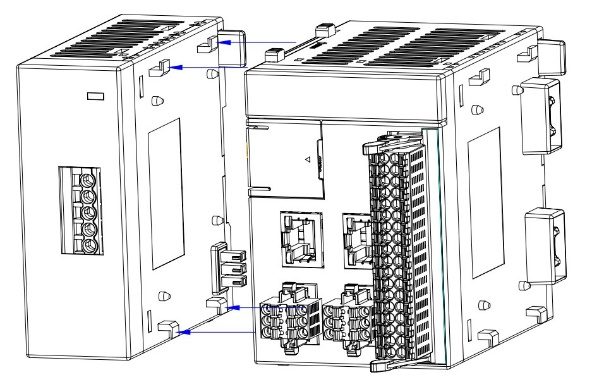
- Release the Side Buckle/Side Slider at the upper/lower side of the high speed or local I/O module.
- Put your finger on the protruding point of the Side Buckle and then push it towards you, i.e., sliding it towards the front side of the module until the module is ready for installation.
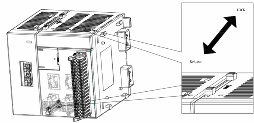 2. Move the hook hole of the high speed or local I/O module towards the left and then insert it into the hook of the advanced module.
- Keep both module parallel to each other. The connection is completed when the butting connection heads of the expansion modules are aligned with each other.
3. Secure the side buckles at the upper and lower sides of the high speed or local I/O module.
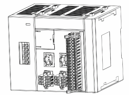 Put your finger on the protruding point of the Side Buckle and then push it outward, i.e., sliding it towards the backside front of the module until the module goes into the LOCK status.
4. Finally, install the termination cover plate on the rightmost end of the entire row of modules.
|
|
Precaution |
Please secure the neighboring module with the Side Buckle. If not secured correctly, it may cause a loosening of the connection between both modules such that the PLC will not be able to operate normally. After being latched, test with your hand to see if both modules are securely connected. |

|
|
Veuillez vous assurer d’utiliser correctement les clips latéraux afin de fixer solidement les modules adjacents. En cas de fixation incorrecte, la connexion entre les modules peut devenir lâche, ce qui peut entraîner un dysfonctionnement du PLC. Une fois la fixation terminée, testez légèrement la connexion à la main pour vérifier sa stabilité. |
 Précaution
10-1-2 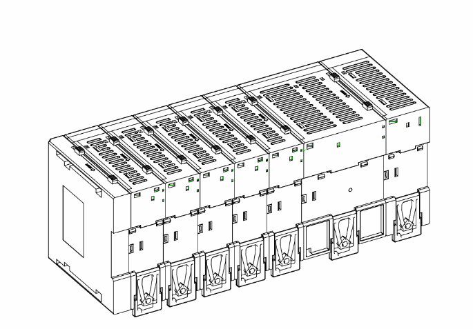 Securing the DIN guide rail
This section describes how to install the connected modules onto the DIN guide rail and the relevant dismantling method.
Install onto the DIN guide rail
1. Hook the groove at the upper side groove of the DIN guide rail onto the guide rail installation latch-hook mounted at the upper side of each module.
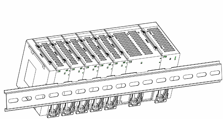 2. Insert the lower side of the guide rail into the DIN guide rail mounting latch-hook at the lower side of each module.
- Push the bottom-side latch-hook to the pull-out status with a flat-head screwdriver. After hearing a click sound, push the module against the DIN guide rail and then lift the bottom-side installation latch-hook to the inserted status.
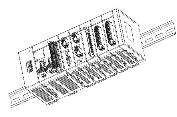 When used in the location difficult for installation, dismantle all of the side buckles first and then lock them tightly after being installed onto the guide rail.
- Check if the lower-side guide rail installation latch-hook is under the inserted status (locking status).
Dismantling method
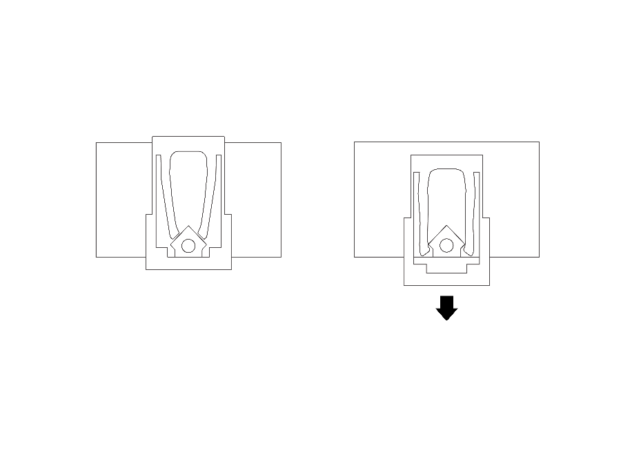 3. Push the lower-side guide rail installation latch-hook to the pull-out status.
4. Dismantle the guide rail from the module according to the reverse procedure to the installation.
10-1-3 Cautions for distribution panel assembly
When installing the PLC in the control panel, it should be executed in an appropriate operating environment.
|
Temperature control |
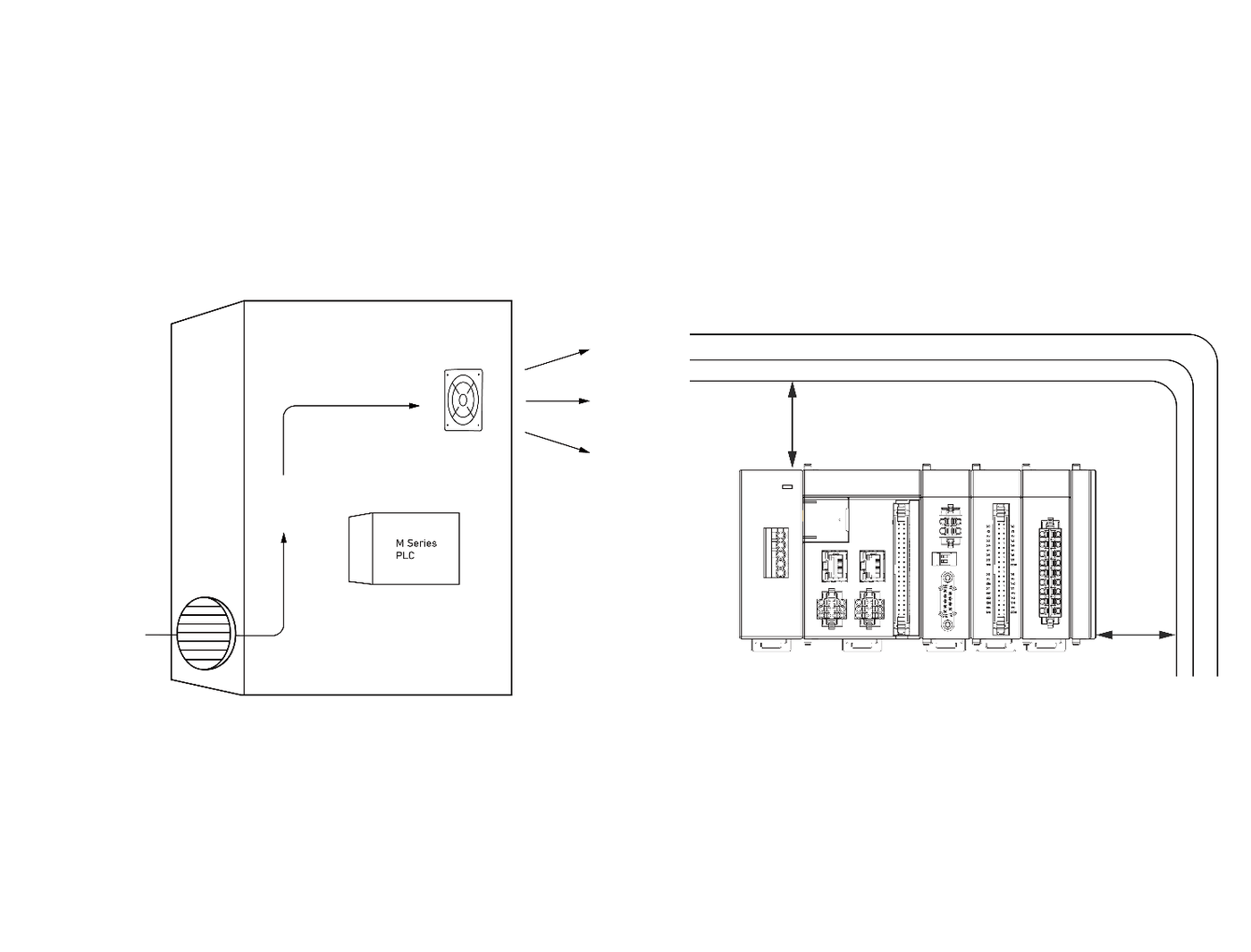 The environment temperature in the Control Box must be maintained at between 00C and 550C. If required, use the following method to maintain it at appropriate temperature level.
- Provide sufficient space in order to maintain effective air circulation.
- Do not install the PLC near equipment that will produce high heat such as heater, transformer or high power resistor.
- If the environment temperature is exceeding 550C, then such environment shall be provided with a cooling fan or an air-conditioning system.
La température de l’environnement dans le boîtier de contrôle doit être maintenue entre 00C et 550C. Si nécessaire, utilisez la méthode suivante pour la maintenir au niveau de température approprié.
- Prévoir un espace suffisant pour maintenir une circulation d’air efficace.
- N’installez pas l’automate à proximité d’équipements produisant une chaleur élevée, tels qu’un chauffage, un transformateur ou une résistance de forte puissance.
- Si la température de l’environnement dépasse 550°C, cet environnement doit être équipé d’un ventilateur de refroidissement ou d’un système de climatisation.
|
Operations and maintenance |
- Keep the PLC away from high-voltage equipment and motorized machineries in order to ensure the safety when executing the operations and maintenance activities.
- Install the PLC at a location higher than the ground for 1.0~1.6m because such location will be most suitable for executing the PLC installation and operations.
|
Improve the interference resistant performance |
When laying the communication cables at an outdoor location, the following factors should be considered:
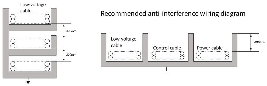
- When using multi-core signal cables, do not install the I/O wires and other type of control wires in the same strand of cable.
- When using a parallel layout, a minimum 300mm gap should be maintained between the distribution frames.
- If it is required to lay the I/O wires and the power cable in the same cable trough, then the grounding metal plate shall be used to separate both cables.
On-board configuration example
|
PLC grounding |
When the terminals are properly grounded, the noise from the power supply can be attenuated. The following are the key points for grounding M series PLCs.
- The ⏚ contact of the MPA module is the equipment ground. When using it, a dedicated ground should be used as much as possible. Under normal circumstances, no current flows in the ground wire (it must not be shared with other return circuits with current return).
- Do not share grounding with large electric machines such as motors/inverters. Grounding should be set individually to avoid mutual influence.
- When using the ⏚ contact of the MPA module, the common mode noise of the power supply may be attenuated, but sometimes it may cause noise reception due to grounding. If grounding still cannot improve the noise situation, it is recommended to remove it.
- When using the G contact of the communication module for grounding, this contact is the signal ground and should be connected together with the G contacts of other communication modules. The G contact should not be connected to the system ground point.
10-2 Wiring
Precautions for the wiring operations
|
Precautions |
|
|
Do not attempt to execute the installation or the wiring activities under energized conditions or it may cause the electrocution of the operator or product damage. |
|
|
The product should be properly grounded according to the grounding symbols marked on the equipment in order to keep the product from executing false actions as maybe caused by the electrocution and noise interference. When connecting the wires between the peripheral devices and the PLC, please check if the product specifications are compatible with the selected PLC. Unsuitable peripheral devices may result in incompatible terminal configuration or incorrect power. In this case, it may not be able to activate the equipment or may even generate hazardous situation such as the equipment burning damage due to the short circuit of the wires. It is required to ensure that foreign matter such as iron chips or wiring residues are not remain in the module, because these foreign matter may cause fire, damage or false working results. |
|


- Grounding
(1) Please use independent correct grounding method.
(2) The grounding should be achieved with the cable with sectional profile greater than or equal to 2mm.
(3) The grounding point should be closer to the PLC as much as possible in order to connect with the grounding cable securely.
Précautions pour les opérations de câblage
|
Précautions |
|
|
– N’essayez pas d’effectuer l’installation ou le câblage dans des conditions d’alimentation électrique, sous peine d’électrocuter l’opérateur ou d’endommager le produit. |
|
|
– Le produit doit être correctement mis à la terre conformément aux symboles de mise à la terre marqués sur l’équipement afin d’éviter que le produit n’exécute des actions erronées pouvant être causées par l’électrocution et les interférences sonores. – Lors de la connexion des fils entre les périphériques et l’automate, veuillez vérifier si les spécifications du produit sont compatibles avec l’automate sélectionné. Des périphériques inadaptés peuvent entraîner une configuration incompatible des bornes ou une alimentation incorrecte. Dans ce cas, il peut être impossible d’activer l’équipement ou même générer des situations dangereuses telles que la brûlure de l’équipement en raison d’un court-circuit des fils. – Il est nécessaire de s’assurer que des corps étrangers tels que des copeaux de fer ou des résidus de câblage ne restent pas dans le module, car ces corps étrangers peuvent provoquer un incendie, des dommages ou des résultats de travail erronés. – The product is Open type, intended to be installed in a final enclosure. – Câblage de la fiche du bornier d’alimentation, taille 12-28 AWG. – La température nominale du fil d’alimentation utilisé doit être d’au moins 105°C. – Utiliser uniquement des conducteurs en cuivre. |
|


- Mise à la terre
(1) Veuillez utiliser une méthode de mise à la terre indépendante et correcte.
(2) La mise à la terre doit être réalisée à l’aide d’un câble dont le profil de section est supérieur ou égal à 2 mm.
(3) Le point de mise à la terre doit être le plus proche possible de l’automate afin de se connecter au câble de mise à la terre en toute sécurité.
10-2-1 Power wiring
Power preventive measures |
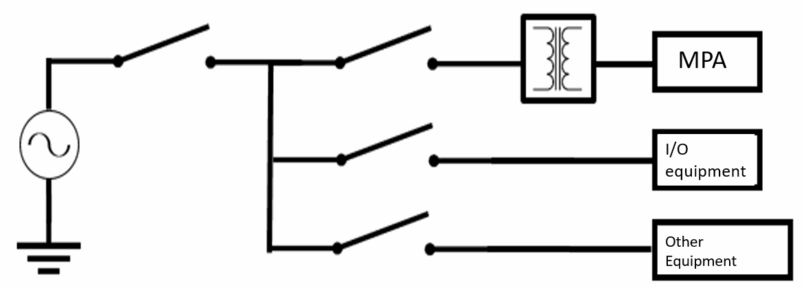
(1) The power cord of the M-Series Power Module should be configured by separating the power cord of I/O device and other devices, as indicated in the figure below. If a stronger noise is expected, then it shall be equipped with an additional Isolation transformer.
(2) AC110V and 220V cables should be arranged by separating with DC24V cables. These power wires shall be finely stranded to prevent noise interference. In the meantime, the cable shall be connected to the module with shorter length.
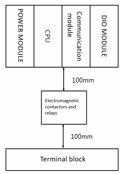
(3) Do not wrap AC110V, AC220V and DC24V cables together with the main circuit (high-voltage/large current) or I/O signal wires and do not lay the cables by keeping them closer to each other. If allowed by the environment, the aforesaid cables should be separated from each other for over 100mm.
(4) To prevent the surge resulting from lightning, please install the surge absorber according to the method indicated in the figure below.
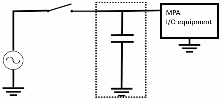
Cautions:
1. The grounding wire of the Surge Arrestor should be configured by separating it from that of PLC System.
2. Please select the surge absorber with a working voltage not less than the allowable maximum input voltage.
Mesures préventives en matière d’électricité |
(1) Le cordon d’alimentation du module d’alimentation de la série M doit être configuré en séparant le cordon d’alimentation du dispositif d’E/S et d’autres dispositifs, comme indiqué dans la figure ci-dessous. Si un bruit plus fort est attendu, il doit être équipé d’un transformateur d’isolation supplémentaire.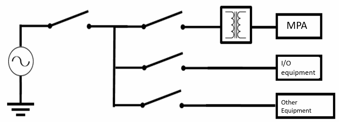
(2) Les câbles AC110V et 220V doivent être séparés des câbles DC24V. Ces câbles d’alimentation doivent être finement toronnés pour éviter les interférences sonores. Entre-temps, le câble doit être connecté au module avec une longueur plus courte.
(3) Ne pas enrouler les câbles AC110V, AC220V et DC24V avec les fils du circuit principal (haute tension/grand courant) ou les fils de signal E/S et ne pas poser les câbles en les rapprochant les uns des autres. Si l’environnement le permet, les câbles susmentionnés doivent être séparés les uns des autres de plus de 100 mm.
(4) Pour éviter les surtensions dues à la foudre, veuillez installer l’absorbeur de surtensions conformément à la méthode indiquée dans la figure ci-dessous. 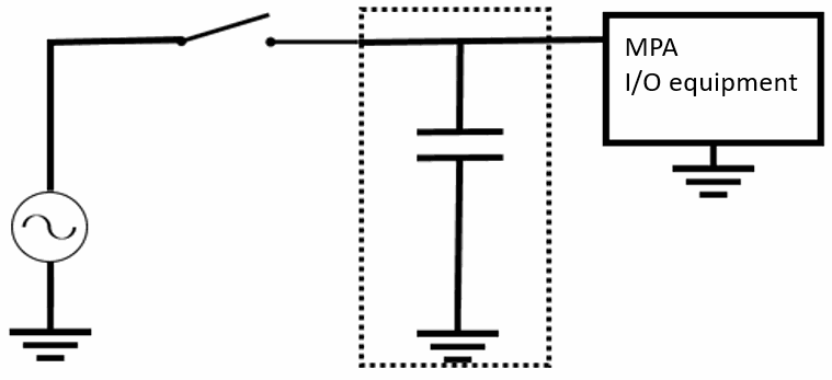
Précautions :
1. Le fil de mise à la terre du limiteur de surtension doit être configuré en le séparant de celui du système PLC.
2. Veuillez sélectionner l’absorbeur de surtension dont la tension de fonctionnement n’est pas inférieure à la tension d’entrée maximale autorisée.
10-2-2 AC power wiring
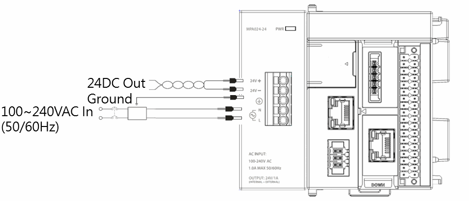
AC Power Loop
1. Connect the FG (⏚) of the Power Module to the grounded end of the power source for use as the reference grounded standard to prevent the system from acting abnormally.
2. Connect the “L” and “N” of the AC power wire to the “L” and “N” of the Power Module, respectively.
The input type shall be AC input. When using, please check the following:
■ Because the input voltage of the AC power is presented in a wider range (100~240VAC), please connect the power to the “L” and “N” terminals. It will result in PLC damage if connecting the AC110V or AC220V to the “+24V” and “-24V” input ends. Therefore, users shall pay special attention to this point.
■ The grounded end of the power uses over 1.6mm wire for carrying out the grounding purpose.
■ If the power outage duration is less than 10ms, then the PLC will keep operating without any influence. If the power outage duration is too long or if the voltage is dropping, then it will force the PLC to stop running and then the output ends will also be disconnected in the meantime. When restoring the power, the PLC will resume running automatically. (The PLC is provided with auxiliary relay and register for supplying the power continuously during a power outage period. During the program design and planning stage, the user shall use these functions carefully.)
3. The DC power supply of the power module is the output side of the power supply, please do not use it in parallel with other power supplies.
10-2-3 DC wiring
- MPLC-Series CPU Module can be activated through the plug-in 24V DC power. Per the figure below, the module is connected to the power socket on the left- side of the CPU module through a 3-pin EU-standard terminal plug.
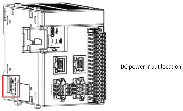
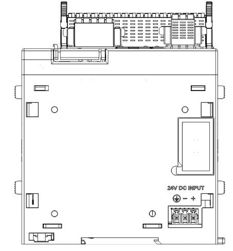 When connecting the DC power, be sure to confirm that it has been properly connected to the positive and negative poles; otherwise, it may result in equipment damage. Please connect the wires according to the correct method indicated in the figure below.
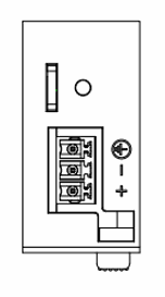
Cautions
1. The grounded wire should be connected separately. If separate grounding becomes impossible, please use common grounding, but the same wire length must be used.
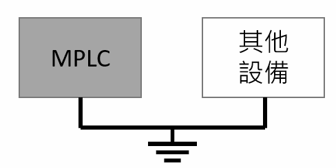
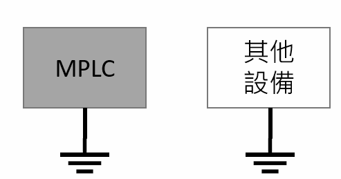 2. Please use the FG terminal as the grounded end (do not use the power terminal as the grounding end).
10-3 Compact module expansion board installation
- Press the buckles on the top and bottom of the expansion bezel and pull up the expansion bezel.
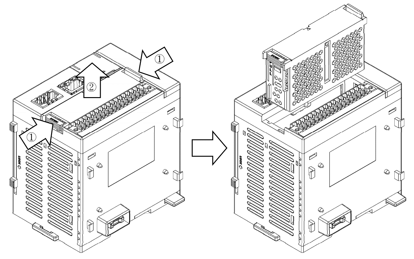
Remove expansion baffle method
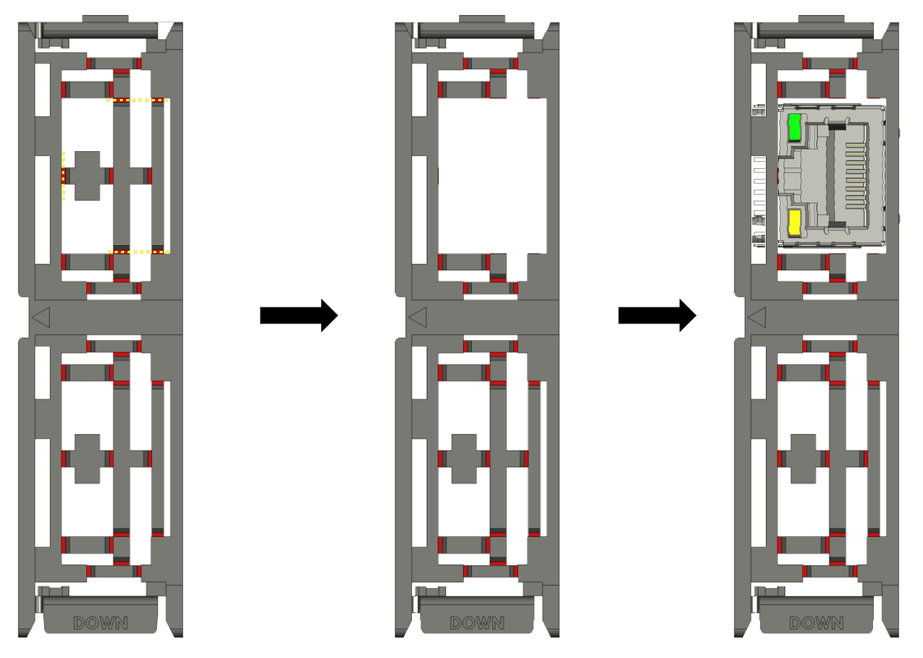
- Cut off the support piece at the yellow dotted line of the expansion board bracket in the picture below according to different types of expansion boards.
Expansion board model: MB-CB5, MB-2HSC, MB-4X, MB-2PSO◇, MB-4Y◇.
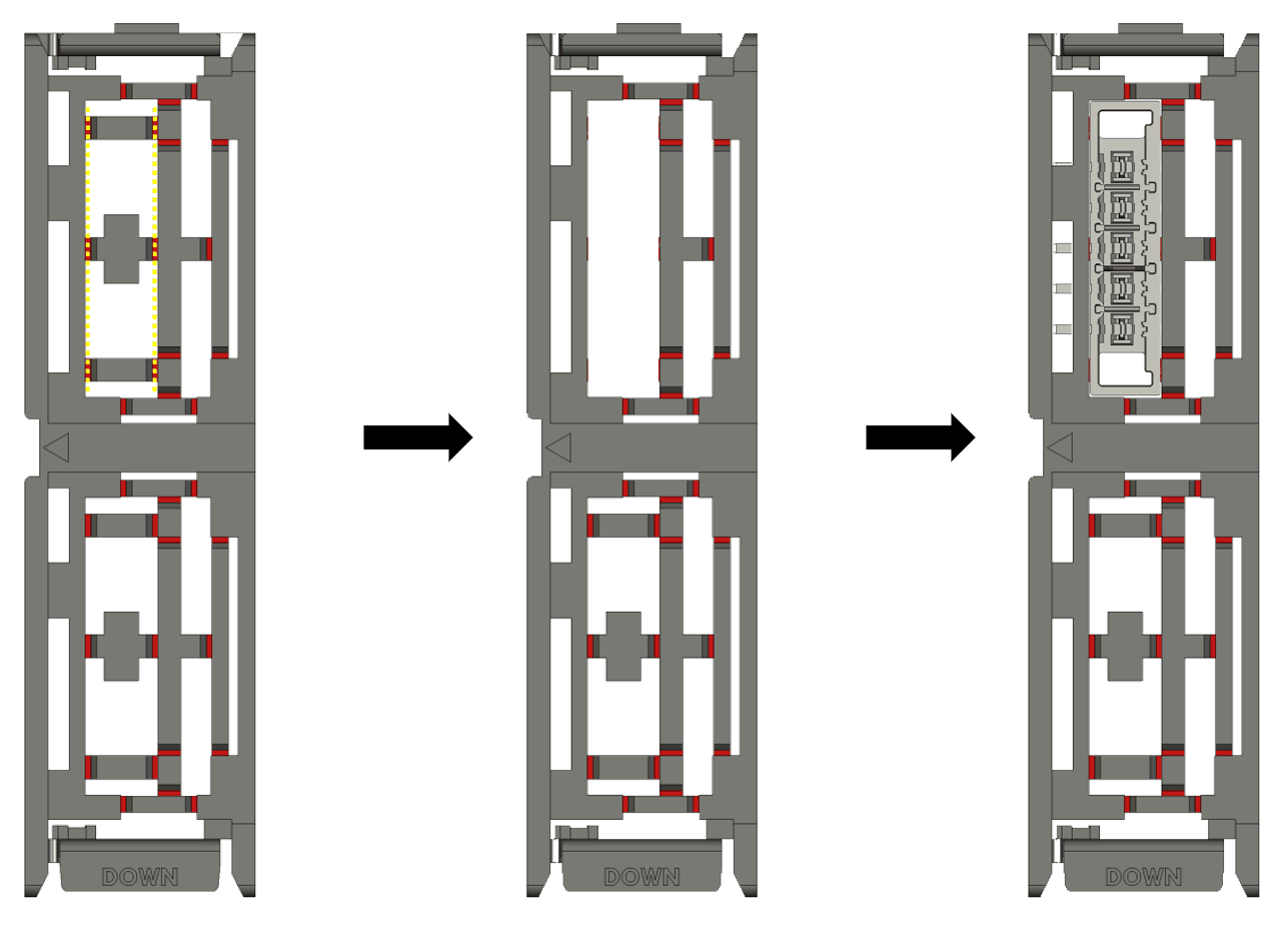
Expansion board model: MB-CB2
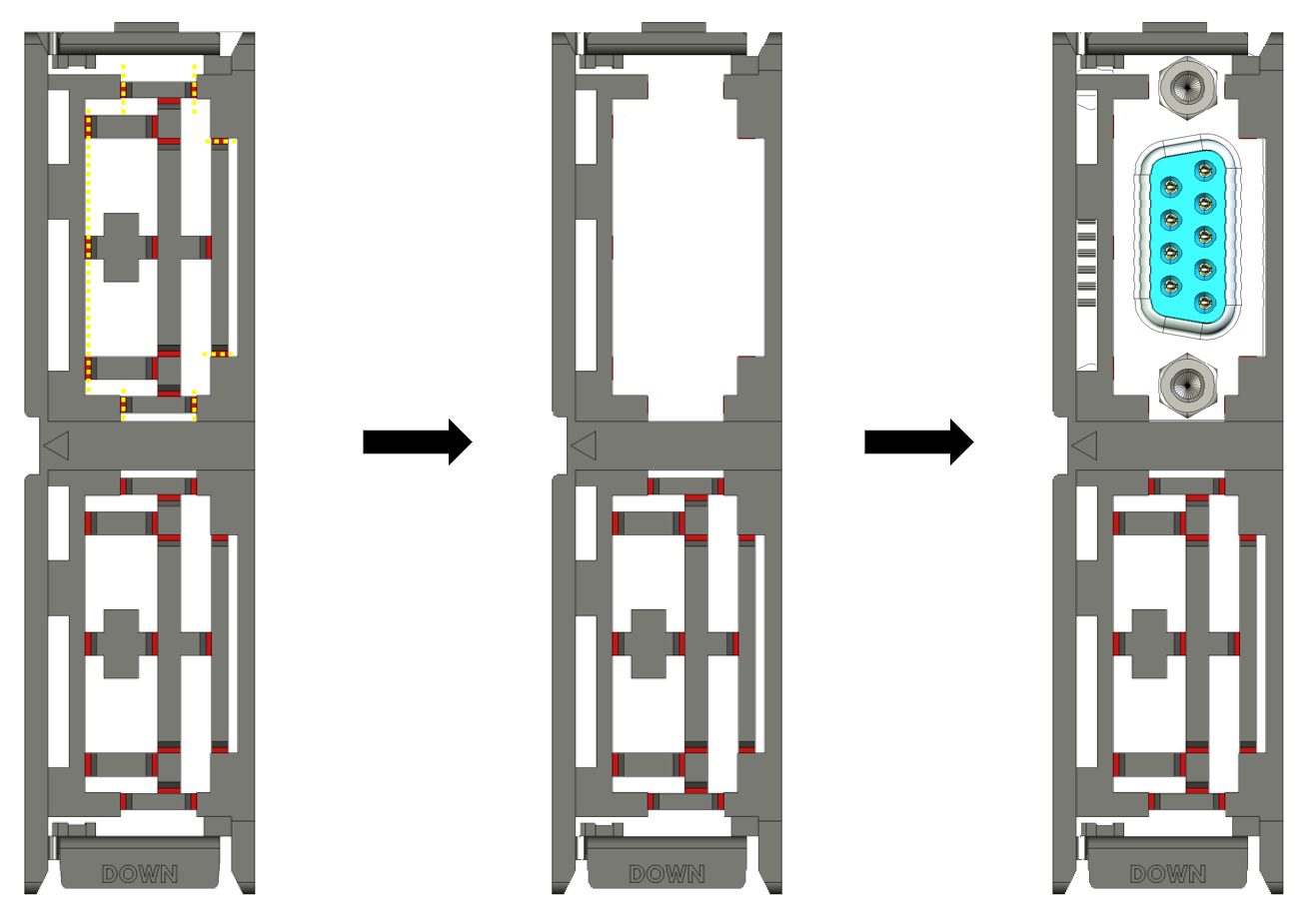
Expansion board model: MB-CBES, MB-CBEH
- Insert the expansion board along the groove inside the expansion board bracket (indicated by the black arrow).
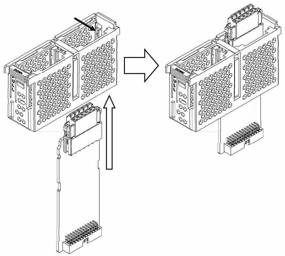
How to install the expansion board to the expansion board bracket
- Attach the nameplate that comes with the expansion board.
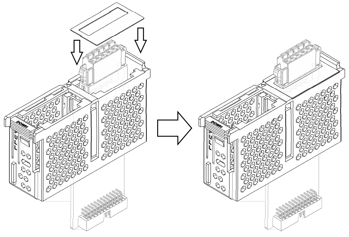
Attach the nameplate of the expansion board
- Install the expansion board including the expansion bracket to the MQ series host.
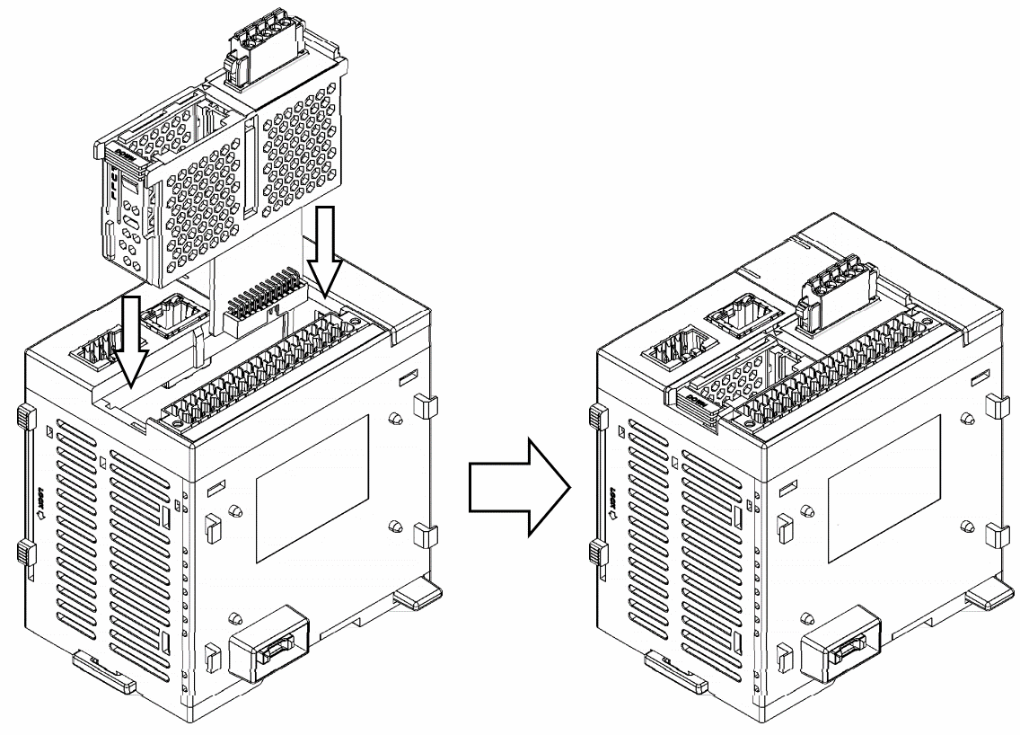
Install expansion boards including expansion brackets to the MQ series host
- Press the buckles on the top and bottom of the expansion bracket, and use a flat-blade screwdriver to lift the expansion bracket at the point indicated by the black arrow.
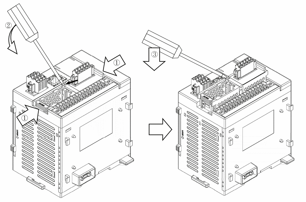
Remove the expansion bracket containing the expansion board
Tip: press ← → to switch chapters, Ctrl+K to search