|
⚠Danger |
|
|
⚠Danger |
|
3-1 Environmental Specifications
|
⚠Caution |
|
|
⚠ Prudence |
|
Environmental Specifications Table
|
Item |
Specification |
note |
|
Operating Ambient Temperature |
0~55℃ |
Permanent Installation |
|
Storage Temperature |
-25 ~ +70℃ |
|
|
Relative Humidity (non-condensing) |
20 ~ 90% |
|
|
Pollution Level |
Dergree Ⅱ |
|
|
Altitude |
≦2000m |
|
|
Vibration (Fixed by DIN RAIL) |
5~8.4Hz Amplitude: 3.5mm 8.4~150Hz Constant acceleration:19.6m/s^2(2G) 10G, 10 times each along the 3 axes (IEC61131-2 Standard) |
|
|
Shock |
10G, 3 times each along the 3 axes |
|
|
Noise Suppression |
1500Vp-p,Width 1us |
|
|
Withstand Voltage |
1500 VAC 1 minute (Between power terminals and input/output terminals, and between all external terminals and the housing) |
|
⚠Warning |
|
The listed environmental specifications are for M Series PLC under normal operation. Any operation in environment not conform to above conditions should be consulted with FATEK. |
|
⚠ Avertissement |
|
Les spécifications environnementales énumérées concernent les automates de la série M en fonctionnement normal. Toute opération dans un environnement non conforme aux conditions ci-dessus doit être consultée auprès de FATEK. |
3-2 Installation Precautions
To avoid interference, the PLC should be installed to keep from noise sources such as high- voltage or high- current and high-power switches. Other precautions are:
The installation that the safety of any system incorporating the equipment is the responsibility of the assembler of the system.
L’installation ainsi que la sécurité de tout système intégrant l’équipement relèvent de la responsabilité de l’assembleur du système.
If the equipment is used in a manner not specified by the manufacturer, the protection provided by the equipment may be impaired.
Si l’équipement est utilisé d’une manière non spécifiée par le fabricant, la protection fournie par l’équipement peut être altérée.
3-2-1 Placement of PLC
Fixation of M Series PLC, which can be fixed by DIN RAIL, should place vertically and start from the CPU module on the left to the expansion module on the right.
The high-speed expansion module requires two communication ports, so the high-speed expansion modules must be connected to the CPU module (Main unit) before the local I/O modules. A maximum of six high-speed modules can be connected, and without an I/O bus extension module, each CPU module can support up to 16 expansion modules. It should be noted that the number and types of modules that can be connected may vary slightly depending on the CPU model.
A typical figure of placement is shown below:
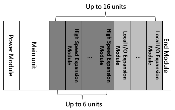
Placement of M series PLC installation
3-2-2 Placement of I/O Bus Extension Module(Repeater, MRPWE)
When the power module can’t provide enough power for all the expansion modules, a “Repeater module" can be appropriately added to share the load of the power module. The repeater module is equivalent to the 48W power module. A maximum of 16 Local I/O expansion modules can be installed between a power module and a repeater module. A maximum of 16 Local I/O expansion modules can be installed between the repeater module and the next repeater module. A total of 64 expansion modules (Local I/O expansion plus High-speed expansion modules) can be installed.
The following figure shows the placement of repeater modules:
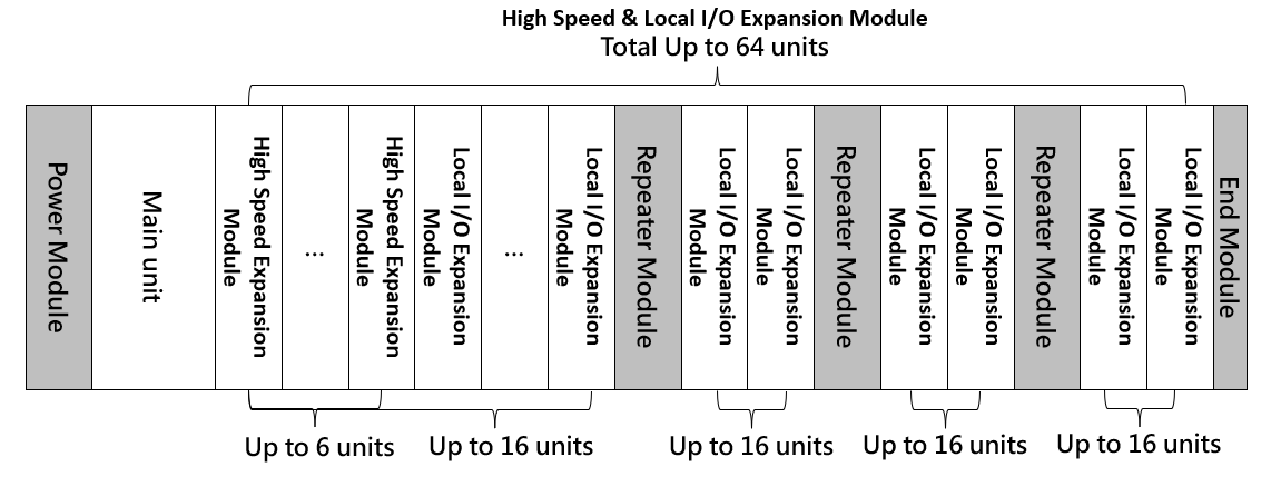
Placement of Repeater Module
3-2-3 Placement of I/O Bus Extension Module (MRGH & MRGT)
When the control cabinet is not wide enough to accommodate the right expansion module, an I/O Bus extension module (Head and Tail module) can be installed to extend the Local I/O modules to the next row. Only a maximum of 16 Local I/O modules expansion modules can be installed in the right side of the Head module, with maximum of 5 Tail modules in a total of 6 rows. A total of 64 expansion modules (Local I/O expansion plus High-speed expansion modules) can be installed
*The Head module itself does not have the power supply function and only has the function of I/O Bus Extension, so the power module must be installed in the left side of Head module.
The following figure shows the placement of Head/Tail modules:
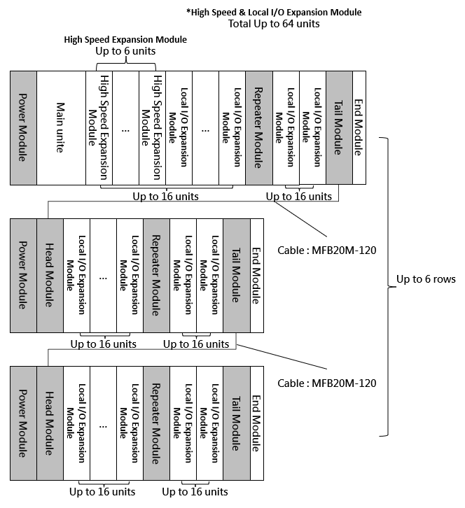
Placement of Head/Tail Module installation
3-2-4 Ventilation Space for Installation
The heat in M Series PLC is ventilated via air circulation. There should reserve more than 50mm space, both below and above PLC, and with vertical installation, for ventilation. as shown in the figure below :
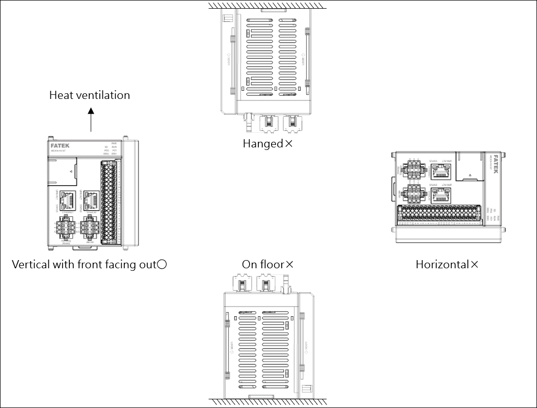
M Series PLC installation direction
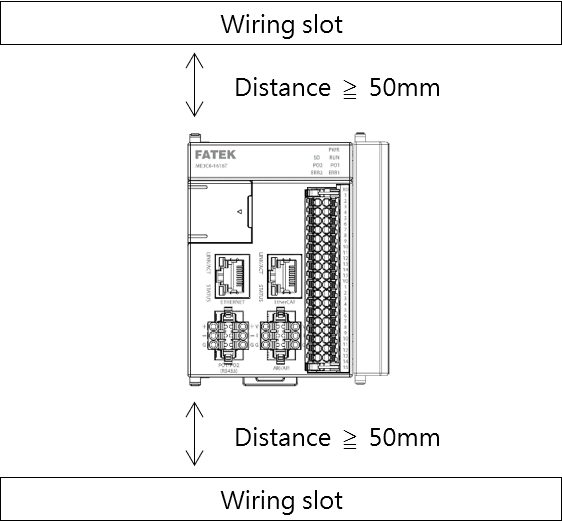
M Series PLC ventilation space
3-2-5 Fixation by DIN RAIL
In an environment with slight vibration (less than 0.5G), this is the most convenient way of fixation and is easy for maintenance. Please use DIN EN50022 DIN RAIL, as shown in the figure below.
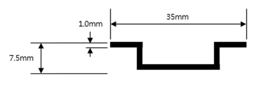
DIN RAIL SIZE
Mount
Hold PLC facing its front, press it down with a 15 degrees tilt onto the DIN RAIL. Swing it down until the upper edge of DIN RAIL groove on PLC back touches the upper tab of DIN RAIL. Then use this locked-in point as a pivot to press the PLC forward on the bottom and lock it in position. The procedure is illustrated below.
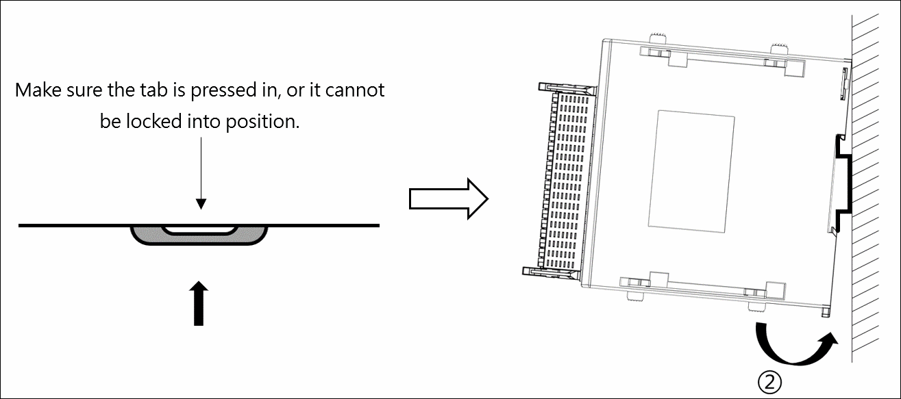
Mount DIN RAIL
Dismount
Use a long screwdriver to reach in the hole on the DIN RAIL tab. Pull out the tab to “pulled out” position to remove PLC, as shown in the figure below.
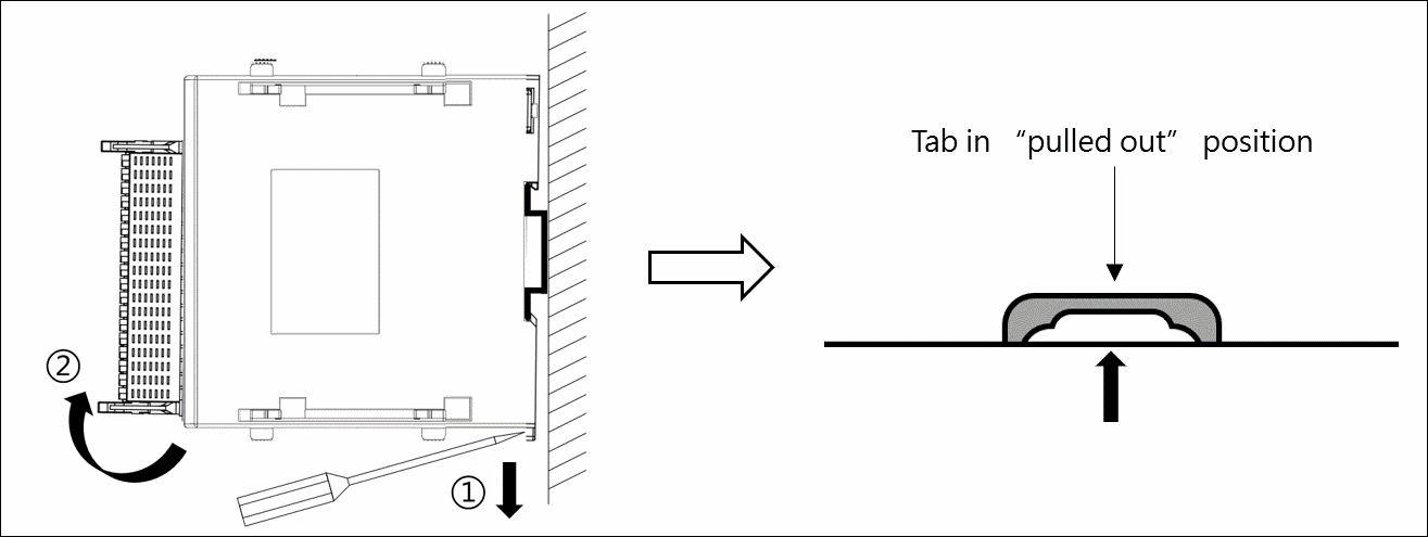
Dismount DIN RAIL
When used in the vibration source, it is recommended that a DIN RAIL damper should be installed on the leftmost and rightmost sides of the M-Series PLC, respectively. In this way, it can stabilize all the modules, including the CPU module and expansion module per the leftmost and rightmost DIN RAIL dampers indicated in the figure below.
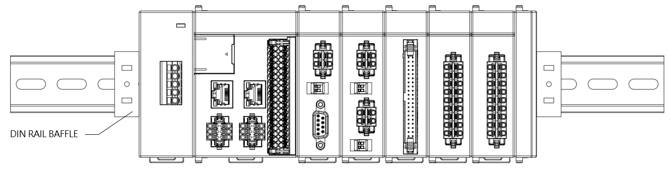
DIN RAIL BAFFLE
3-2-6 Installation of Expansion Modules
Expansion module installation method: after aligning the expansion module with the CPU Module slot or with the slot of the previous expansion module, insert the module and then push the latch-hook straight down to the base, as indicated in the figure below.
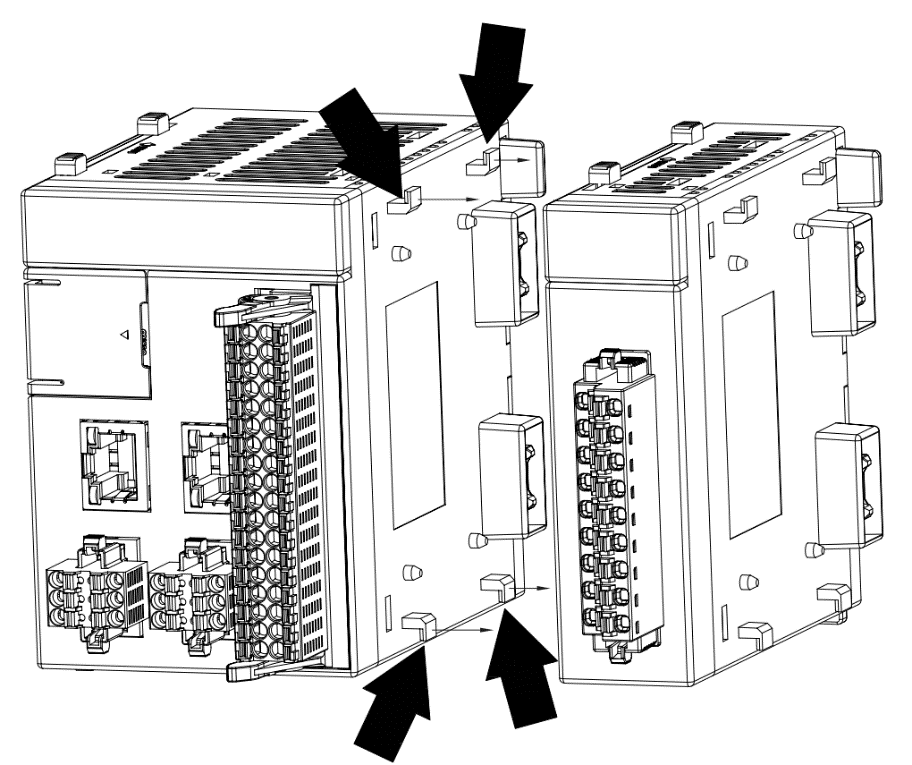
Install expansion module
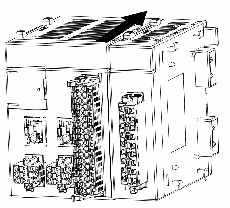
Install the expansion module buckle
3-2-7 Installation and Remove of Plug-in Expansion Boards
- Press the top and bottom clips of the expansion case, then pull it upwards.
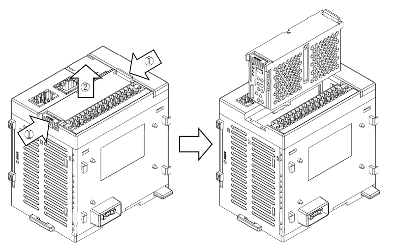
Remove expansion panel method
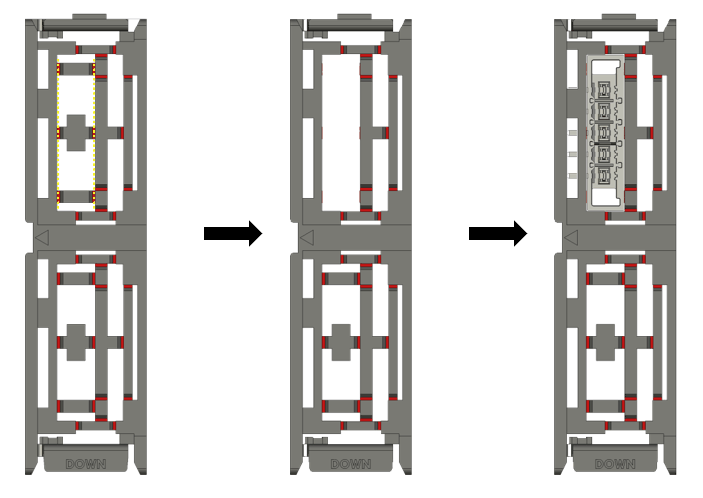
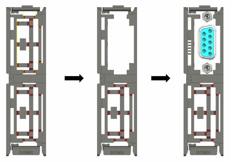
- Cut off different support piece on the bracket(case) along the dotted line according to different plug-in expansion boards.
Plug-in expansion board: MB-CB5,MB-2HSC,MB-4X,MB-2PSO◇,MB-4Y◇
Plug-in expansion board: MB-CB2
- Insert the plug-in expansion board into the groove inside the bracket (by the black arrow).
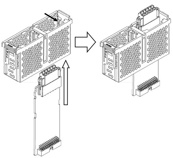
Insert the plug-in expansion board into the plug-in expansion board bracket method
- Paste the nameplate that comes with the module。
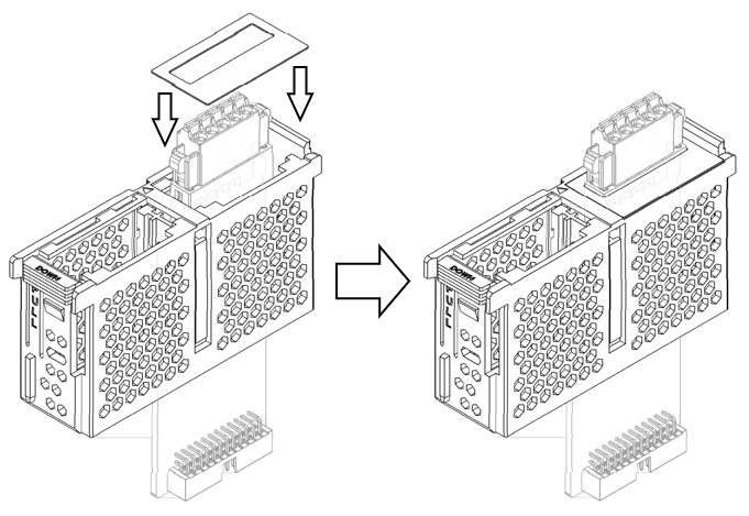
Paste the nameplate
- Install the plug-in expansion board including the expansion bracket(case) to the MQ CPU.。
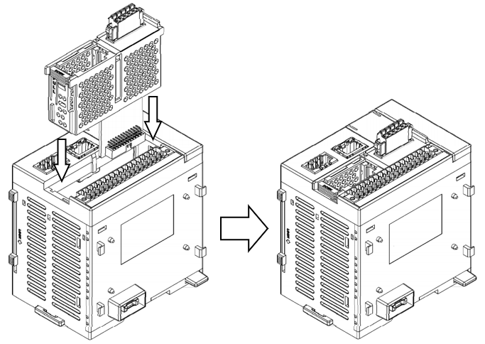
Install the plug-in Expansion Board to the MQ CPU.
- Press the clips on the top and bottom of the expansion bracket. and use a flat-blade screwdriver to lift the expansion bracket at the point by the black arrow.
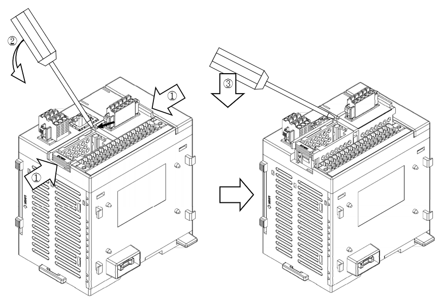
Remove the Plug-in Expansion Board
3-2-8 Mount European Terminal Block
- EU-standard terminal installation method: align the EU-standard terminal with the slot of the expansion module and then push it straight downward, as indicated in the figure below.
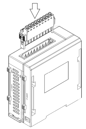
Mount European terminal Block
- EU-standard terminal removing method: push the fastener on both ends of the EU-standard terminal downward and then lift both of them upward and you can take out the terminal, as indicated in the figure below.
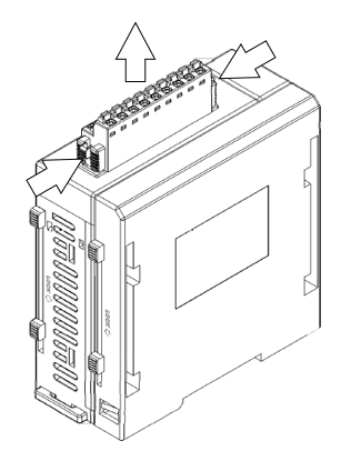
Dismount European terminal Block
3-2-9 DIO Converter Module and European terminal wiring
- During the wiring of M Series PLC, please follow local national standards or regulations for installation.
- The product is Open type, intended to be installed in a final enclosure.
- Power Terminal Block plug wiring size 18-24 AWG.
Câblage de la fiche du bornier d’alimentation, taille 18-24 AWG.
- The rating of the power wire used must be at least 105°C.
La température nominale du fil d’alimentation utilisé doit être d’au moins 105°C
- Use Copper Conductors Only.
Utilisez uniquement des conducteurs en cuivre.
- Shorter wires are preferred. It is advised that the length of I/O wiring does not exceed 100m (10m for high-speed input).
- Input wiring should be separated from output or power wiring (at least 30~50mm apart). In case separation is not possible, adopt vertical crossing, no parallel wiring is allow.
- The specifications of the crimp sleeve for the DIO Converter Module and the European terminal are as follows:
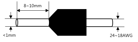
Crimp Sleeve Specifications
3-2-10 DIO Converter Module Installation
- First fix the upper clip and then install the DIO Converter module into the DIN RAIL in the direction of the arrow.
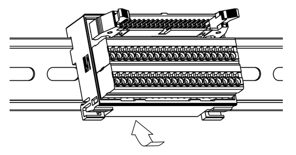
Install DIO Converter Module
- Please push up in the direction of the No. 1 arrow first and then pull out in the direction of the No. 2 arrow to disassemble.
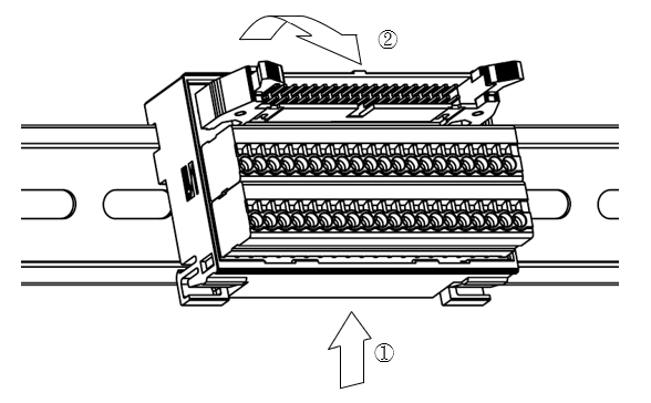
Disassemble DIO Converter Module
Tip: press ← → to switch chapters, Ctrl+K to search