The expansion of M series PLC means when the resources provided by the M series CPU module are insufficient or the interface not provided by the CPU module. The number of I/O or interface types can be expanded by adding expansion modules. The expansion of M series PLC can be divided into many categories: Local I/O expansion, High-speed expansion, Plug In expansion, and Advanced expansion…etc.
2-1 I/O Expansion Specifications
The expansion of M Series PLC I/O consists of Digital I/O (DI/O, which status is represented by a single bit) and the Numeric I/O (NI/O, which status is represented by a 16-bit Word). Either the DI/O or the NI/O expansion is realized through expansion modules cascaded through the usage of the “I/O Output Expansion Connector” located at the right side of M Series PLC or expansion module.
The I/O points of M Series PLC are limited to 2048 points of DI/O (1024 points each for DI and DO),512 words of NI/O (The sum of NI and NO does not exceed 512). Hardware limitations: ①. A maximum number of 64 modules can be used in the expansion. ②The number of expansion modules that can be connected in series in each segment of the M series PLC is limited to 16 units, and repeater modules or branch modules must be used for extension between each segment.
|
⚠Caution |
|
|
⚠Warning |
|
|
⚠ Prudence |
|
|
⚠ Avertissement |
|
2-2 Digital I/O Expansion and I/O Numbering
Digital I/O means I/O with the discrete type of status, including digital input (with initial X in DI numbering) and digital output (with initial with Y in DO numbering). The DI and DO of M Series PLC can both be expanded up to 1024 points (numbered as X0~X1023 and Y0~Y1023, each with 1024 points).
The status of input contacts (X0~X1023) of PLC comes from the input signal connected to the digital input terminal block on CPU Module or expansion module; while the status appears at digital output terminal block of CPU Module and expansion module reflects the digital output relay (Y0~Y1023) status inside PLC.
On the M Series CPU Module, at the position right of the European terminal connector, there have labels indicate the corresponding signal name. They label each terminal with numbers representing the corresponding digital input contact Xn and digital output relay Yn. In the example of the CPU module in ME3C6-1616T, The labels of the digital input contacts on the left side of the European terminal connector are X0~15, S/S and the labels of the digital output contacts on the right side of the European terminal connector are Y0~15, COM. Users only need to locate the printed label for each terminal to find out its I/O number. The LED status display region also indicates the ON/OFF status for all DI(X0~X15) and DO(Y0~Y15) on the main unit. Users can easily find each terminal with its I/O number and LED status indication.
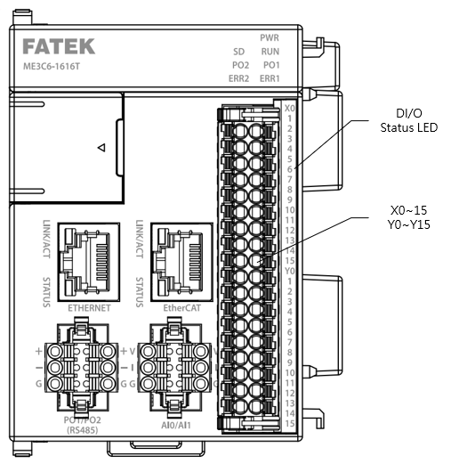
CPU Module Digital I/O Number
While the various expansion modules other than the CPU module have the same printed labels on the input/output terminals as the CPU module do, these labels are only relative I/O numbers, different from the absolute I/O numbers on CPU module. The number of a terminal only represents its order on the expansion module. For example, the first contact is 1, the second 2, etc. All numbers on the expansion module begin with 1. The actual number of digital input contact or digital output contact, however, is determined by summing the numbers on all previous expansion modules and the CPU module. See the following figure and its calculation.
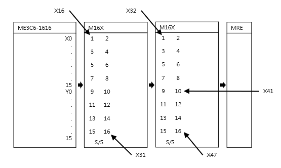
Expansion Module Digital I/O Number
As shown in the above figure, digital input point 10 on the 2nd expansion module M16X. Because the top X numbers of the previous two units are 15 and 16, respectively, the number of input contact X10 on second expansion unit should be:
X (15+16+10) = X41
2-3 Numeric I/O Expansion and I/O Channel Mapping
The numeric I/O in M Series PLC treats 16 single-bit data as one 16-bit numeric data (Word) ranging from the 0~65535. Since all numeric data of M Series PLC are stored in the register inside PLC (16-bit width), therefore numeric I/O is also called register I/O. The Input Register (IR) has 256 Word (R34768 ~ R35023) for inputs from external numeric input (NI) module, and the Output Register (OR) also has 256 Word (R35024 ~ R35279) for outputs to external numeric output (NO) module.
Analog Input Modules and Temperature Modules are Numeric input (NI) modules which use input register (IR) to convey the status. Analog Output Modules are Numeric output (NO) modules which output is directly from the Output register (OR). The Analog Input, Temperature Input, and Analog Output is of analog voltage or current. Either the magnitude of voltage or current is represented by the 16-bit value of the corresponding register. The corresponding current/voltage signal of any IR or on the NI/O module is named as a Channel (CH). The channels on the NI module are called numeric input channels (NI channels) and those on NO module numeric output channels (NO channels). The number of IR/OR used by NI and NO channels on each module varies depending on the module type or working mode. The following table lists the numbers of IR and OR used by NI and NO channels on each NI/O module:
Numeric I/O Expansion and I/O Channel Mapping
|
Module Name |
NI Channel Label |
NO Channel Label |
Number of IR occupied (Word) |
Number of OR occupied (Word) |
Note |
|
MB-2ADL |
CH0 |
1 |
The voltage and current inputs can’t be used in the same channel at the same time. It only one (V or I) available. |
||
|
CH1 |
1 |
||||
|
MB-2DAL |
CH0 |
1 |
The voltage and current inputs can’t be used in the same channel at the same time. It only one (V or I) available. |
||
|
CH1 |
1 |
||||
|
M04AD |
CH0 |
1 |
The voltage and current inputs can’t be used in the same channel at the same time. It only one (V or I) available. |
||
|
CH1 |
1 |
||||
|
CH2 |
1 |
||||
|
CH3 |
1 |
||||
|
M04ADS |
CH0 |
2 |
The voltage and current inputs can’t be used in the same channel at the same time. It only one (V or I) available. |
||
|
CH1 |
2 |
||||
|
CH2 |
2 |
||||
|
CH3 |
2 |
||||
|
M08ADS |
CH0 |
2 |
The voltage and current inputs can’t be used in the same channel at the same time. It only one (V or I) available. |
||
|
CH1 |
2 |
||||
|
CH2 |
2 |
||||
|
CH3 |
2 |
||||
|
CH4 |
2 |
||||
|
CH5 |
2 |
||||
|
CH6 |
2 |
||||
|
CH7 |
2 |
||||
|
M04ADR |
CH0 |
2 |
The voltage and current inputs can’t be used in the same channel at the same time. It only one (V or I) available. |
||
|
CH1 |
2 |
||||
|
CH2 |
2 |
||||
|
CH3 |
2 |
||||
|
M04DA |
CH0 |
1 |
The voltage and current outputs can’t be used in the same channel at the same time. It only one (V or I) available. |
||
|
CH1 |
1 |
||||
|
CH2 |
1 |
||||
|
CH3 |
1 |
||||
|
M04DAR |
CH0 |
1 |
The voltage and current outputs can’t be used in the same channel at the same time. It only one (V or I) available. |
||
|
CH1 |
1 |
||||
|
CH2 |
1 |
||||
|
CH3 |
1 |
||||
|
M0202AH |
CH0 |
1 |
The voltage and current inputs can’t be used in the same channel at the same time. It only one (V or I) available. |
||
|
CH1 |
1 |
||||
|
CH0 |
1 |
The voltage and current outputs can’t be used in the same channel at the same time. It only one (V or I) available. |
|||
|
CH1 |
1 |
||||
|
M04TC |
TC0 |
2 |
|||
|
TC1 |
2 |
||||
|
TC2 |
2 |
||||
|
TC3 |
2 |
||||
|
M04TCR |
TC0 |
2 |
|||
|
TC1 |
2 |
||||
|
TC2 |
2 |
||||
|
TC3 |
2 |
||||
|
M04RTD |
P0 |
2 |
|||
|
P1 |
2 |
||||
|
P2 |
2 |
||||
|
P3 |
2 |
||||
|
M0202TH |
TC0 |
2 |
|||
|
TC1 |
2 |
||||
|
RTD0 |
2 |
||||
|
RTD1 |
2 |
||||
|
M02LC |
CH0 |
4 |
|||
|
CH1 |
4 |
||||
|
M02LCR |
CH0 |
4 |
The corresponding IR or number calculation of the NI/O module starts from the first expansion module. The first NI channel corresponds to the first IR register (R34768). Adding R34768 with the number of IR used by the first NI channel gives the IR number of the second NI channel. Adding the IR number of the second NI channel with the number of IR used by the second NI channel gives the IR number of the third NI channel. All other numbers can be obtained accordingly. Similarly, the first NO channel corresponds to the first OR (R35024). Adding R35024 with the number of OR used by the first NO channel gives the OR number of the second NO channel. (In the cumulative calculation of NI channels, care only for NI channels and disregard DI/O and NI. Similarly, in the case of NO channels, disregard DI/O and NI channels.) The following figure helps users find out the relation between NI/O channels and PLC’s IR and OR.
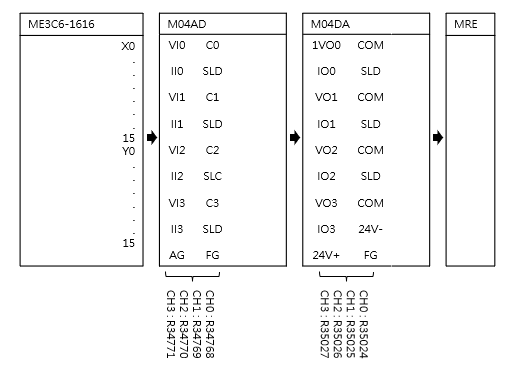
Analog expansion module IR, OR number
The M series PLC will automatically detect the expansion module when it is turned on, and then automatically set the IR and OR, the user does not need to make any settings.
2-4 Expansion Module Configuration Settings
The Expansion Module Configuration of the M-Series PLC is implemented in the “UperLogic→【Project】→【Device View】→Select a Expansion Module→【Configuration】. The Device View is designed to concurrently display the outline dimensions, Module Information (Module ID and Firmware Version), Power Consumption and Module Resources (occupying the register) of different expansion modules, as indicated below.
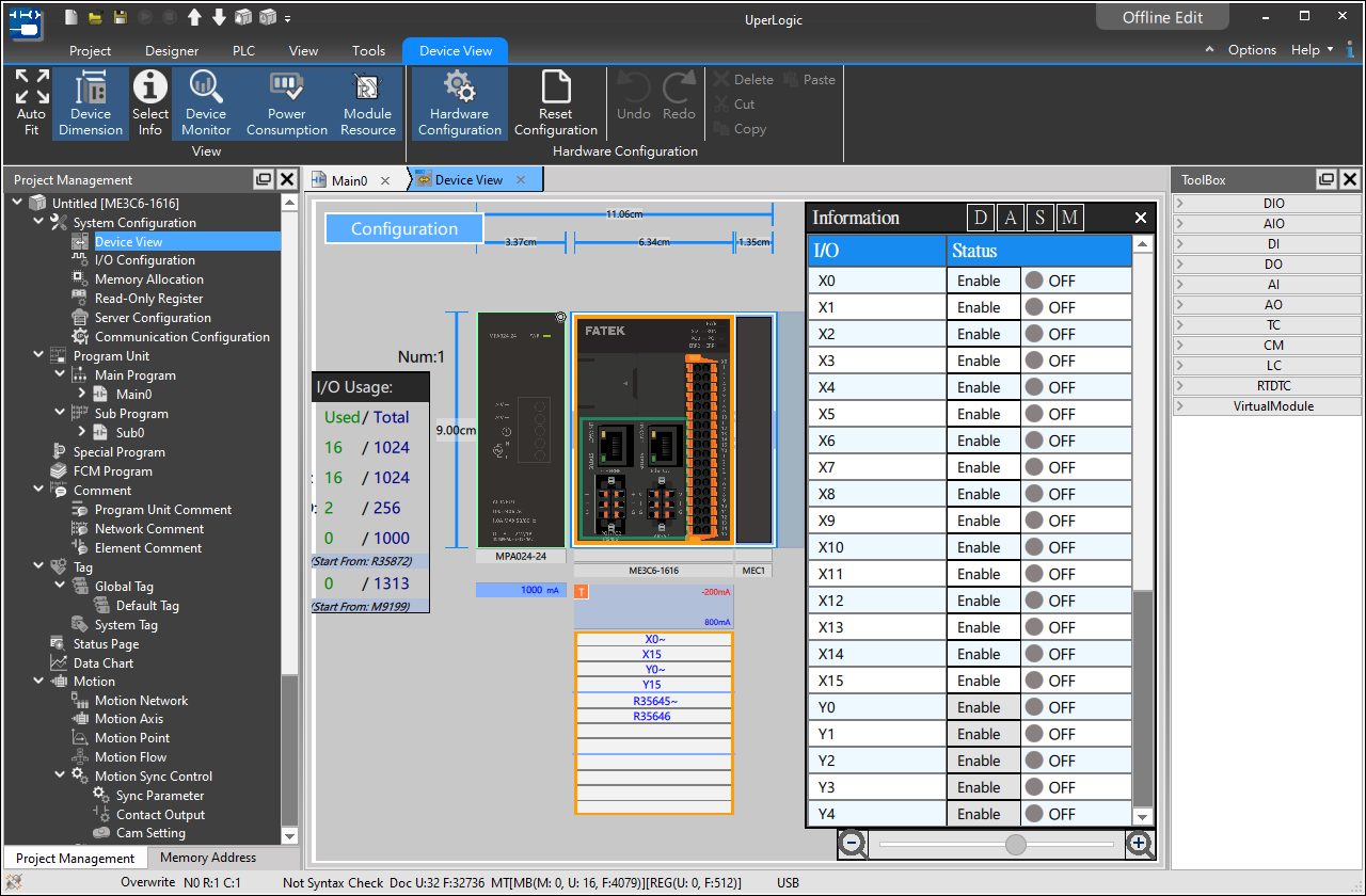
Device View
When being installed in different types of expansion modules, the Expansion Module Configuration of the M-Series PLC will display different types of configuration pages, as indicated below.
The Expansion Module Configuration of the M-Series PLC is saved in the expansion module directly. Even if the CPU module is damaged, such expansion module can still operate independently to show the corresponding processing action. In this way, it not only improves the system stability but also intensifies the system security.
|
⚠Caution |
|
The expansion module configuration of M-Series PLC is saved in the project and the expansion module instead of being saved in the CPU module. Before replacing the expansion module, you need to set the expansion module configuration in the expansion module or save the project on the SD Card and then the CPU module will write the expansion module configuration being saved to the corresponding expansion module. |
|
⚠ Prudence |
|
La configuration du module d’extension de l’API de la série M est enregistrée dans le projet et le module d’extension au lieu d’être enregistré dans le module CPU. Avant de remplacer le module d’extension, vous devez définir la configuration du module d’extension dans le module d’extension ou enregistrer le projet sur la carte SD, puis le module CPU écrira la configuration du module d’extension en cours d’enregistrement sur le module d’extension correspondant. |
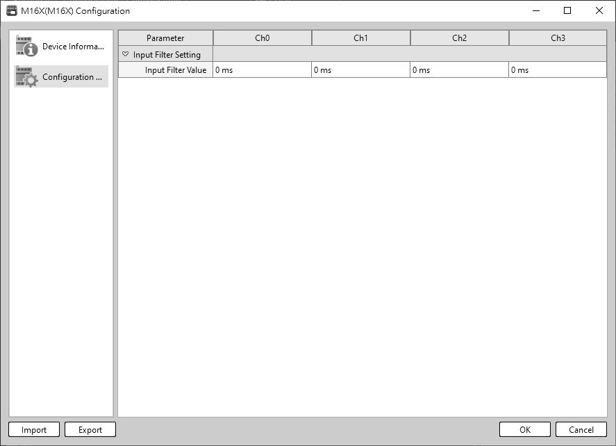
Configuration
2-5 Expansion Module Firmware Update
The expansion module firmware of the M-Series PLC is updated in the “UperLogic→【Project】→【Device View】→Select a Expansion Module→【Device information】” profile. In this regard, the equipment information displays the module name, module ID, module description, module firmware version, module hardware version and module serial number of the expansion module, as indicated below:
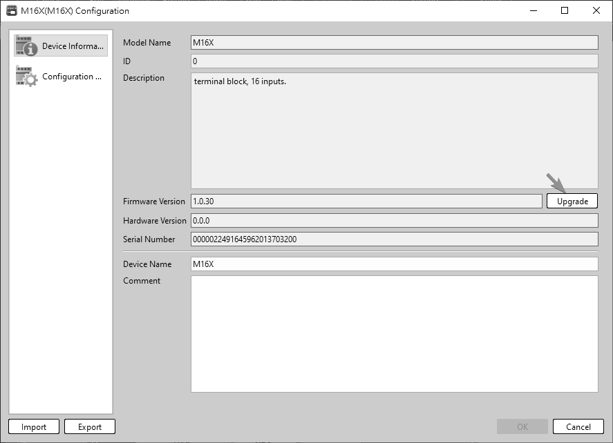
Device Information
The expansion module firmware update of M series PLC can be updated individually or multiple expansion modules can be updated at the same time.
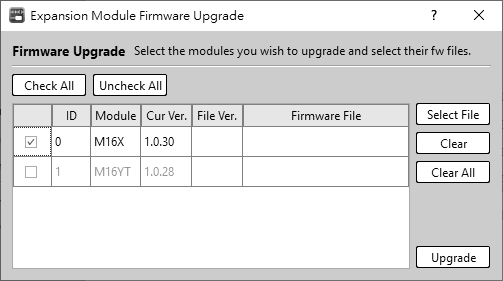
Firmware update
Tip: press ← → to switch chapters, Ctrl+K to search