|
⚠Danger |
|
This section describes the functions that will be displayed in the UperLogic software interface.
Displayed in the webpage below are the UperLogic working window and the status of the respective connection window.
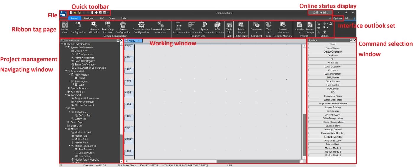
Fig. 8: Webpage configuration
3-1 File
Such function allows the user to perform project operations such as opening a new project, saving a project, saving a new file, importing and exporting, and printing.
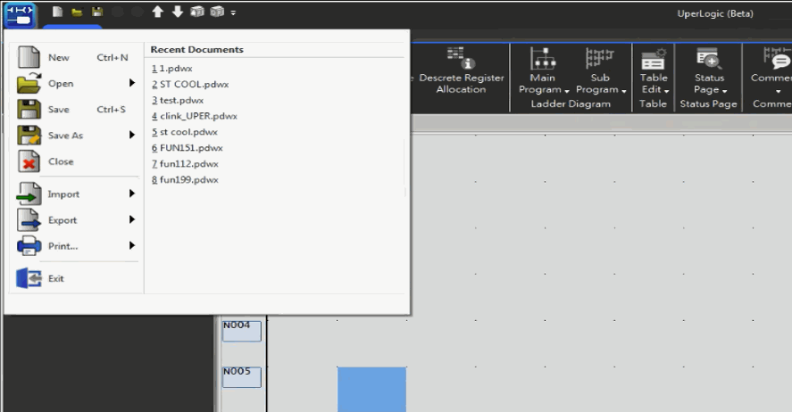
Fig. 9: File
|
Function |
Description |
Detailed introduction |
|
Open new project |
Create a new project for executing the editing. |
Please refer to Section 4.1. |
|
Open project |
Open previously written project for executing the editing. |
Please refer to Section 4.7 |
|
Save project |
Save currently edited project to disk. |
Please refer to Section 4.4. |
|
Save project as |
Save currently edited project as another project name in the disk. |
Please refer to Section 4.5. |
|
Close project |
Close currently edited project. |
|
|
Import |
Import previously saved information to project. |
Please refer to Section 4.6. |
|
Export |
Export the information from project to disk. |
Please refer to Section 4.6. |
|
Exit |
Close UperLogic. |
Table 1: Detailed file function introduction
3-2 Quick Toolbar
The Quick Toolbar allows users to select frequently used functions for quick selection.
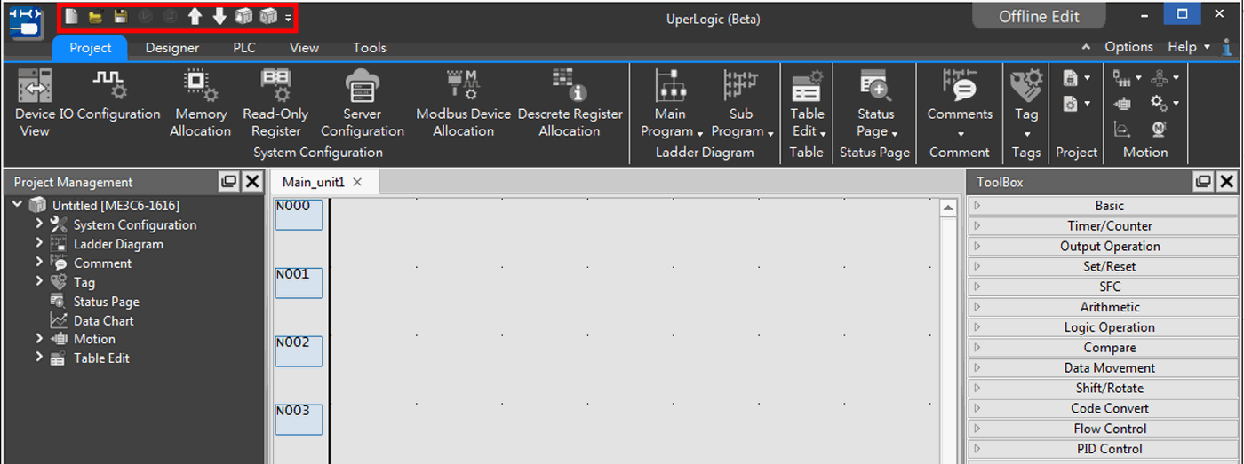
Fig. 10: Quick Toolbar
Quick key will display the function that can be used under current status.
|
Status |
Quick Toolbar display status |
|
Offline editing, and project not opened. |
|
|
Offline editing, and project opened. |
|
|
Online monitoring, and PLC is running |
|
|
Online monitoring, and PLC stops running |
|




Table 2: Quick Toolbar display status
|
Function |
Description |
Detailed Introduction |
|
Open new project |
Create a new project for executing the editing. |
Please refer to Section 4.1 |
|
Open project |
Open previously written project for executing the editing. |
Please refer to Section 4.7 |
|
Save project |
Save currently edited project to disk. |
Please refer to Section 4.4 |
|
Run (F9) |
Run PLC |
Please refer to Section 11.5 |
|
Stop Run (Shift+F9) |
Stops running PLC |
Please refer to Section 11.5 |
|
Upload |
Upload project from PLC to software |
Please refer to Section 11.3 |
|
Download |
Download currently edited project to PLC |
Please refer to Section 11.4 |
|
Clear data |
Clear PLC data |
Please refer to Section 11.6 |
|
PLC status |
Display current PLC status |
Please refer to Section 11.7 |
|
Self-defined quick toolbar |
The user may define its own quick toolbar |
Table 3: Quick toolbar function introduction
3-3 Interface Outlook Setting
This function provides a number of software outlook interfaces for users to execute the adjustment according to their own demand.
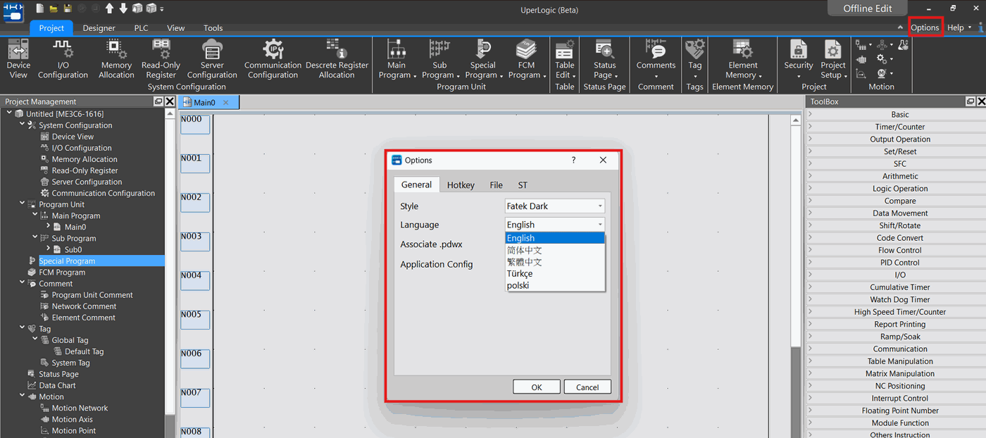
Fig. 11: Interface outlook setting options
|
Format |
Preview |
|
Office Color Mode |
|
|
Fatek Dark Mode |
|
|
Fatek Light Mode |
|
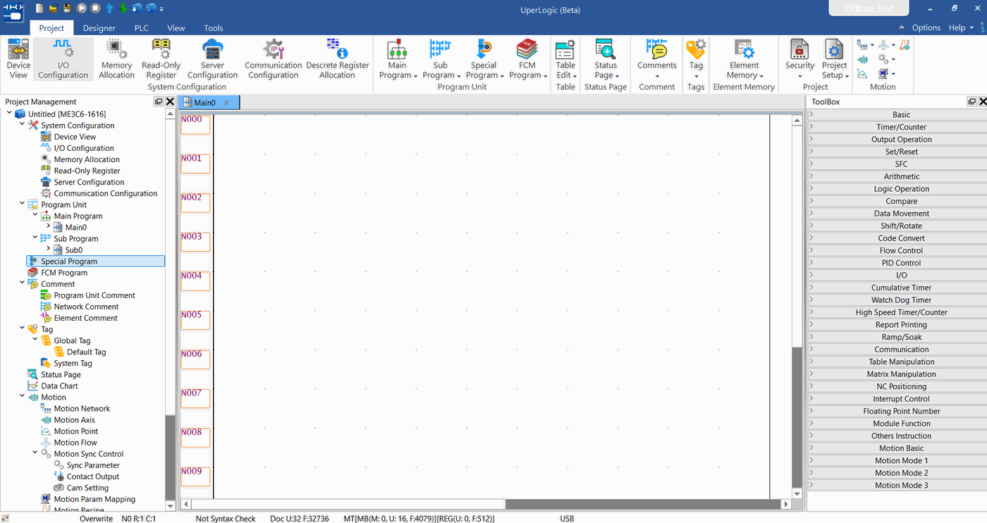
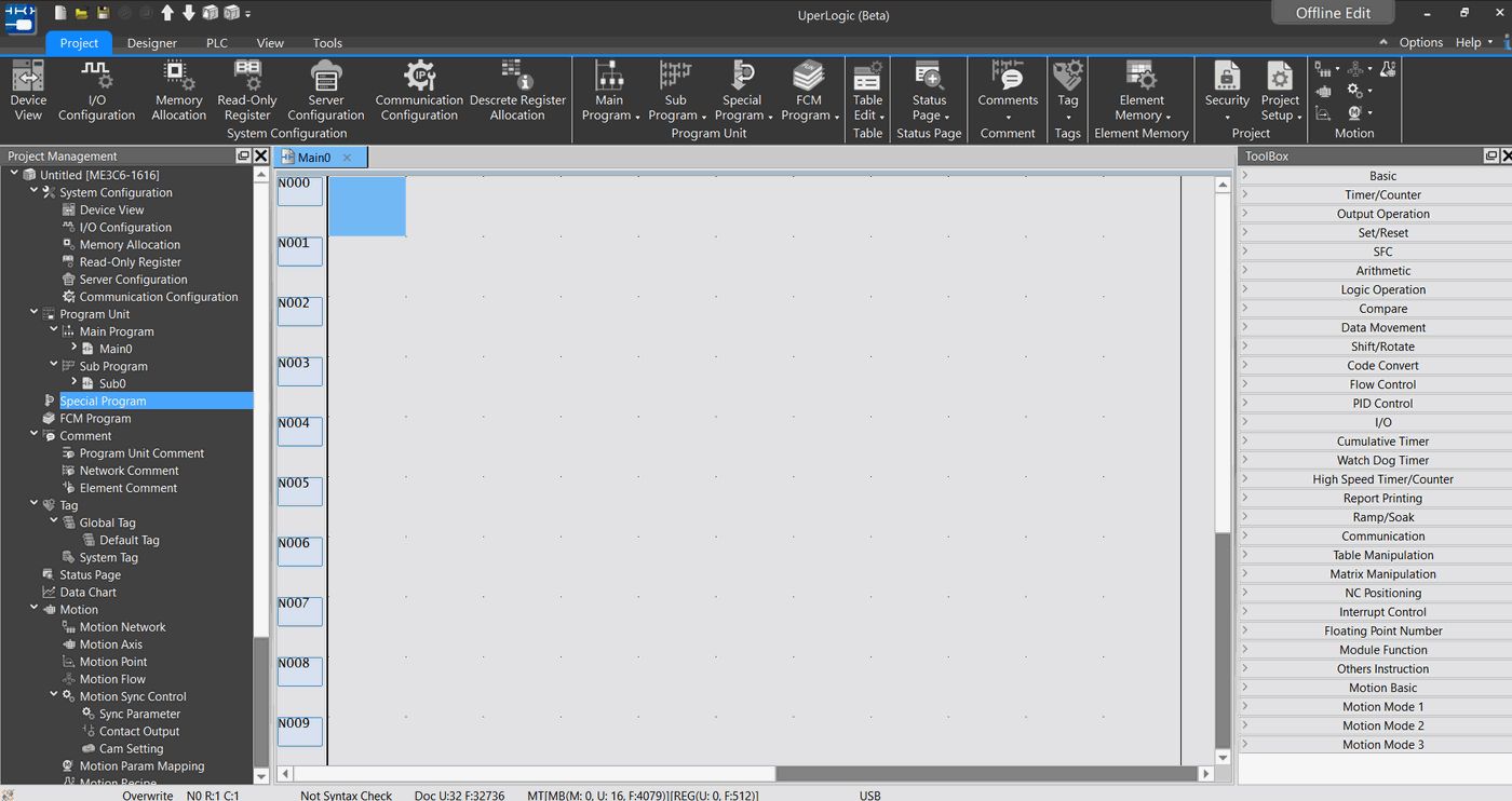
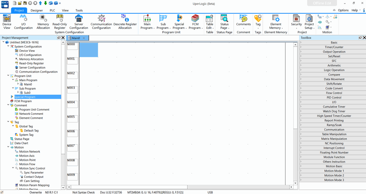
Table 4: Interface outlook format preview
3-4 Ribbon Tag Page
This function is designed to organize the created commands in a “tag” group, and each group comprises the required commands. Each application program corresponds to the related tag group in order to demonstrate the functions that will be provided by the program. Its purpose is allowing the user to search and use the functions of the application program more easily, as per the tag categorization indicated in the figure below.
3-4-1 Project
This tag page is mainly used to set the overall information of the project such as memory configuration and security.

Fig. 12: Project tag page
|
Type |
Function |
Description |
Detailed Introduction |
|
System configuration |
Device View |
The equipment required for planning and checking current status of PLC. |
Please refer to Section 10 |
|
I/O Configuration |
Set the I/O status |
Please refer to Section 5.1 |
|
|
Memory Allocation |
Check current memory configuration |
Please refer to Section 5.2 |
|
|
ROR Register |
Check and edit the read-only Register. |
Please refer to Section 5.3 |
|
|
Server Configuration |
Set the connection between PLC and server |
Please refer to Section 5.4 |
|
|
Communication Configuration |
Check and edit the settings of communication configuration. |
Please refer to Section 5.5 |
|
|
Descrete Register Allocation |
Check current descrete and register Allocation |
Please refer to Section 5.2 |
|
|
Program Unit |
Main Program |
Add or revise Master Program |
Please refer to Section 6.1 |
|
Sub Program |
Add or revise main sub-program |
Please refer to Section 6.1 |
|
|
Special Program |
Add or modify interrupt program or special Ppogram |
Please refer to Section 6.6 |
|
|
FCM Program |
Add or modify function module programs. |
Please refer to Section 6.7 |
|
|
Data Table |
Table Edit |
Set required tables |
Please refer to Section 7 |
|
Status Page |
Status Page |
Check current status of PLC Register |
Please refer to Section 12.2 |
|
Comment |
Comments |
Set and edit the comment |
Please refer to Section 8 |
|
Tag |
Tag |
Tag setting |
Please refer to Section 8.5 |
|
Element Memory |
Element Memory |
Set and edit the element memory |
Please refer to Section 12.3 |
|
Project |
Security |
Edit PLC security related setting. |
Please refer to Section 13 |
|
Option |
Set project automatic backup |
Please refer to Section 4.2 |
|
|
Motion control |
Motion Network |
Edit motion network related setting |
Please refer to Section 9.1 |
|
Motion Axis |
Edit motion axis related setting |
Please refer to Section 9.2 |
|
|
Motion Point |
Edit the motion point related setting |
Please refer to Section 9.3 |
|
|
Motion Flow |
Edit the motion process related setting |
Please refer to Section 9.4 |
|
|
Motion Sync Control |
Edit the motion synchronization related setting |
Please refer to Section 9.5 |
|
|
Motion Param Mapping |
Edit the motion network related setting |
Please refer to Section 9.6 |
|
|
Motion Recipe |
Edit the motion recipe |
Please refer to Section 9.7 |
Table 5: Setting project tag page
3-4-2 Design
 This tab page is mainly used to edit the related design of the ladder diagram and the motion flow block program.
Fig. 13: Designing tag page
|
Type |
Function |
Description |
|
Clip book |
Paste |
Paste the copied or clipped object |
|
Cut |
Cut the selected object |
|
|
Copy |
Copy the selected object |
|
|
Edit |
Delete |
Delete the selected object |
|
Undo |
Restore to previous status |
|
|
Redo |
Cancel the restore |
|
|
Select All |
Select all objects |
|
|
Find/Replace |
Find |
Search object in Ladder Diagram |
|
Replace |
Search and replace corresponding object |
|
|
Goto |
To specific ladder program network bar |
|
|
Ladder Block |
Block Close |
Close ladder block |
|
Block Open |
Open ladder block |
|
|
Network |
Insert |
Insert network in upper or lower side |
|
Expand |
Compress or expand the network |
|
|
Ladder Diagram |
Cursor Arrow |
Return to the mouse status where object is not being selected |
|
A contact |
Constant open contact |
|
|
B contact |
Constant close contact |
|
|
TU contact |
Create a pulse wave when contact is energized (0→1). |
|
|
TD contact |
Create a pulse wave when contact is closed (1→0). |
|
|
Coil |
Send computation result to the coil. |
|
|
Inverse Coil |
Send computation result back to coil |
|
|
Set Coil |
Set the coil. |
|
|
Reset Coil |
Clear the coil. |
|
|
Inverse |
Execute reverse phase for node status. |
|
|
TU Power Flow |
Retrieve upper differential for node status |
|
|
TD Power Flow |
Retrieve lower differential for node status |
|
|
Horizontal Short |
Add horizontal line in Ladder Diagram |
|
|
Vertical Short |
Add vertical line in Ladder Diagram |
|
|
Horizontal Long |
Add long horizontal line in Ladder Diagram |
|
|
Set |
Set all bits for each point or Register (set as 1). |
|
|
Reset |
Clear all bits from each point or Register (set as 0). |
|
|
Timer |
General Timer command |
|
|
Counter |
General Counter command |
|
|
Function |
Set corresponding Function command |
|
|
Cursor Delete |
Delete object from Ladder Diagram |
|
|
Delete Vertical Short |
Delete vertical line from Ladder Diagram |
|
|
Delete Horizontal Long |
Delete horizontal line from Ladder Diagram |
|
|
Zooming |
Open the table setting corresponding to application command |
|
|
Motion Process |
Finish |
Finish motion control |
|
Branch Selection |
Select the corresponding branch |
|
|
Horizontal Branch |
Simultaneous branching |
|
|
Coverage |
Make motion process branches converge |
|
|
Point Reset |
Set the reset process |
|
|
Position Control |
Set the positioning control process |
|
|
Speed Control |
Set speed control process |
|
|
Torque Control |
Set torque control process |
|
|
Standby |
Set standby process |
|
|
Sub-process |
Set up Sub-process |
|
|
Page Skipping |
Skip to other process |
|
|
Synchronizing Control |
Set synchronizing control process |
|
|
Computation |
Execute computing |
Table 6: Setting tag design page
3-4-3 PLC
This tag page is mainly used for editing the Ladder Diagram related design.

Fig. 14: PLC tag page
|
Type |
Function |
Description |
Detailed introduction |
|
PLC |
Run PLC |
Run PLC |
Please refer to Section 11.5 |
|
Stop PLC |
Stop running PLC |
Please refer to Section 11.5 |
|
|
Trail Run |
Test project while editing online |
Please refer to Section 11.10 |
|
|
Discard Change |
Abandon the action of online editing |
Please refer to Section 11.10 |
|
|
Operation |
Upload |
Upload project from PLC to software |
Please refer to Section 11.3 |
|
Download |
Download currently edited project to PLC. |
Please refer to Section 11.4 |
|
|
Syntax Check |
Syntax Check |
Check if syntax error exists in Ladder Diagram |
Please refer to Section 6.5 |
|
Mode |
Offline Edit |
Edit when not connected with PLC. |
Please refer to Section 11.2 |
|
Online Monitor |
Moniter when connected with PLC. |
Please refer to Section 11.1 |
|
|
Online Editing |
Edit when connected with PLC. |
Please refer to Section 11.10 |
|
|
Monitor |
Status Page |
Check current status of PLC Register |
Please refer to Section 12.2 |
|
Data Chart |
The Trend Curve used for checking the change of each Register. |
Please refer to Section 12.2.3 |
|
|
Motion Chart |
Check current status of motion control |
Please refer to Section 9.1.4 |
|
|
Connect |
Connection Parameter |
Set up PLC connection method and relevant parameters |
Please refer to Section 11.1 |
|
Others |
Quick Control |
Set up PLC-related operation in quicker way |
Please refer to Section 11.9 |
|
PLC Setting |
Set up PLC-related setting |
Please refer to Section 11.8 |
|
|
Clear PLC |
Clear PLC data |
Please refer to Section 11.6 |
|
|
PLC Status |
Display current PLC status |
Please refer to Section 11.7 |
Table 7: Setting PLC tag page
3-4-4 View
This tag page is mainly used for editing the Ladder Diagram related design.

Fig. 15: Inspection tag page
|
Type |
Function |
Description |
Detailed introduction |
|
Project Window |
Project Management |
Display or hide project management window. |
Please refer to Section 3.5 |
|
Tool Box |
Display or hide toolkit |
Please refer to Section 3.5.2 |
|
|
Module List |
Display or hide module list |
Please refer to Section 10.2 |
|
|
Memory Address |
Display or hide the memory address |
Please refer to Section 3.5.4 |
|
|
Cross Reference |
Display or hide cross reference |
Please refer to Section 3.5.5 |
|
|
View Setting |
Program Unit Comment |
Display or hide program comment |
Please refer to Section 6.1.5 |
|
Network Comment |
Display or hide network comment |
Please refer to Section 6.2.5 |
|
|
Element Comment |
Display or hide element comment |
Please refer to Section 8.3 |
|
|
Register Value |
Display or hide Register data |
||
|
Longer Text |
Display longer text to avoid excessive truncation |
||
|
Elided Long Text Middle |
Truncating or abbreviating excessively long text. |
||
|
Font |
Font size |
Set font size for Ladder Diagram |
|
|
Window |
Cascade |
Display window overlapping |
Please refer to Section 6.2.1 |
|
Tile Horizontal |
Display entire window array |
Please refer to Section 6.2.1 |
|
|
Switch Window |
Quick switch to corresponding window |
Please refer to Section 6.2.1 |
|
|
Close All |
Close all windows |
Please refer to Section 6.2.1 |
Table 8: Setting inspection tag page
3-4-5 Tools
This tag page is mainly used for editing the Ladder Diagram related design.
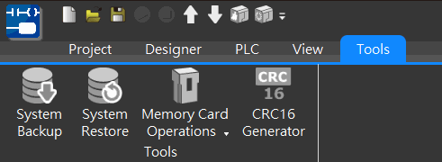
Fig. 16: Tool tag page
|
Type |
Function |
Description |
Detailed introduction |
|
Tools |
System Backup |
Set up and save system project related backup |
Please refer to Section 14.1.1 |
|
System Restore |
Read originally saved system backup data |
Please refer to Section 14.1.2 |
|
|
Memory Card Operations |
Execute memory cartridge related operation |
Please refer to Section 14.2 |
|
|
CRC16 Generator |
System will calculate and produce the checking value automatically |
Please refer to Section 14.3 |
Table 9: Setting tool tag page
3-5 Project Window
3-5-1 Project Management
Such function allows the user to organize regularly used functions into a tree diagram and then display it in the left-hand side Project Management window. By clicking the respective function setting tag under the Project Management, it also allows the user to open the required window in quicker way. For example, click the “IO Configuration” and the relevant setting window will pop up.
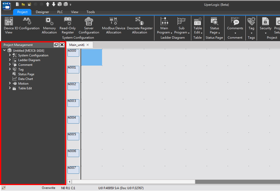
Fig. 17: Project management window
|
Type |
Description |
Detailed introduction |
|
System Configuration |
Check Register related setting |
Please refer to Section 5 |
|
Program Unit |
Check Main Program and sub-program |
Please refer to Section 6.2 |
|
Comment |
Manage the comment deployed in the Ladder Diagram |
Please refer to Section 8 |
|
Status Page |
Monitor current status of Register |
Please refer to Section 12.2 |
|
Data Chart |
Monitor the trend graph of individual register changes |
Please refer to Section 12.2.3 |
|
Motion Control |
Set the motion control related parameters. |
Please refer to Section 9 |
|
Data Table |
Set up various tables |
Please refer to Section 7 |
|
Element Memory |
Set and edit the element memory |
Please refer to Section 12.3 |
Table 10: Setting project management window
3-5-2 Tool Box
For easier operation by users, normal commands are categorized for organizing in the toolkit. By clicking [View]→ [Tool Box] in the function toolbar, the user will be allowed to open the Tool Box command window.
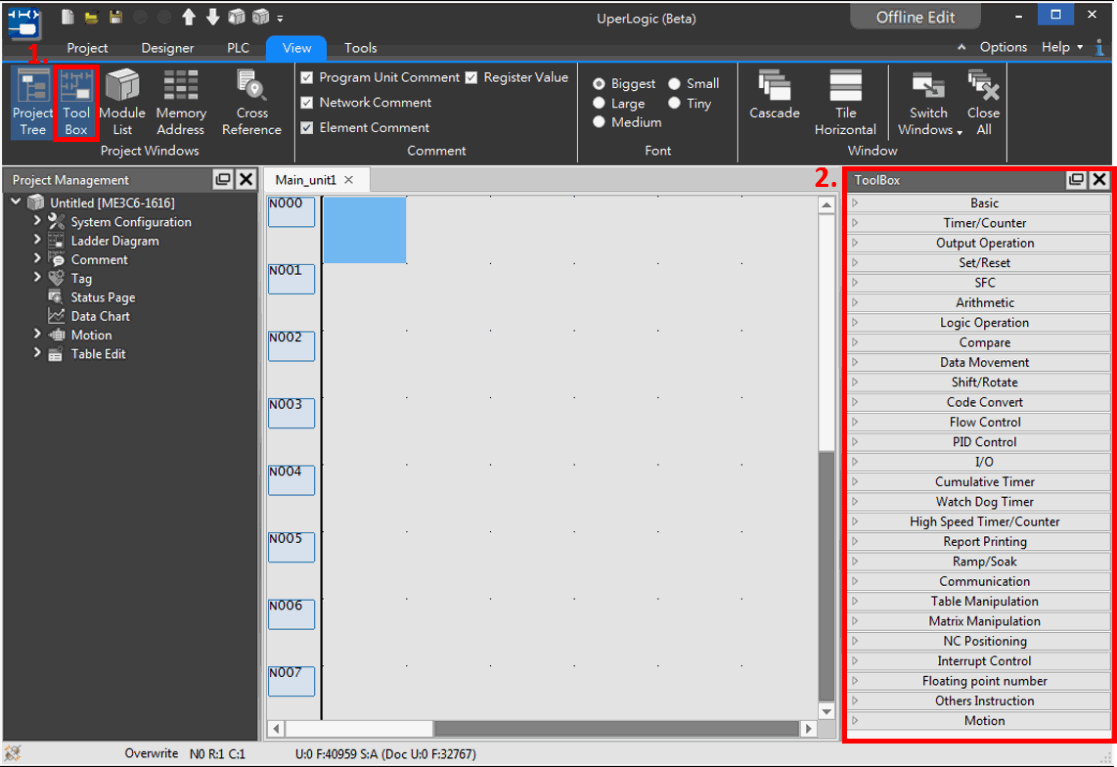
Fig. 18: Tool Box window
For the introduction of the functions in the tool box, please refer to the Instruction User Manual.
3-5-3 Module List
Click [View]→ [Module List] in the function toolbar, the following module management webpage appears, as shown in the figure below:
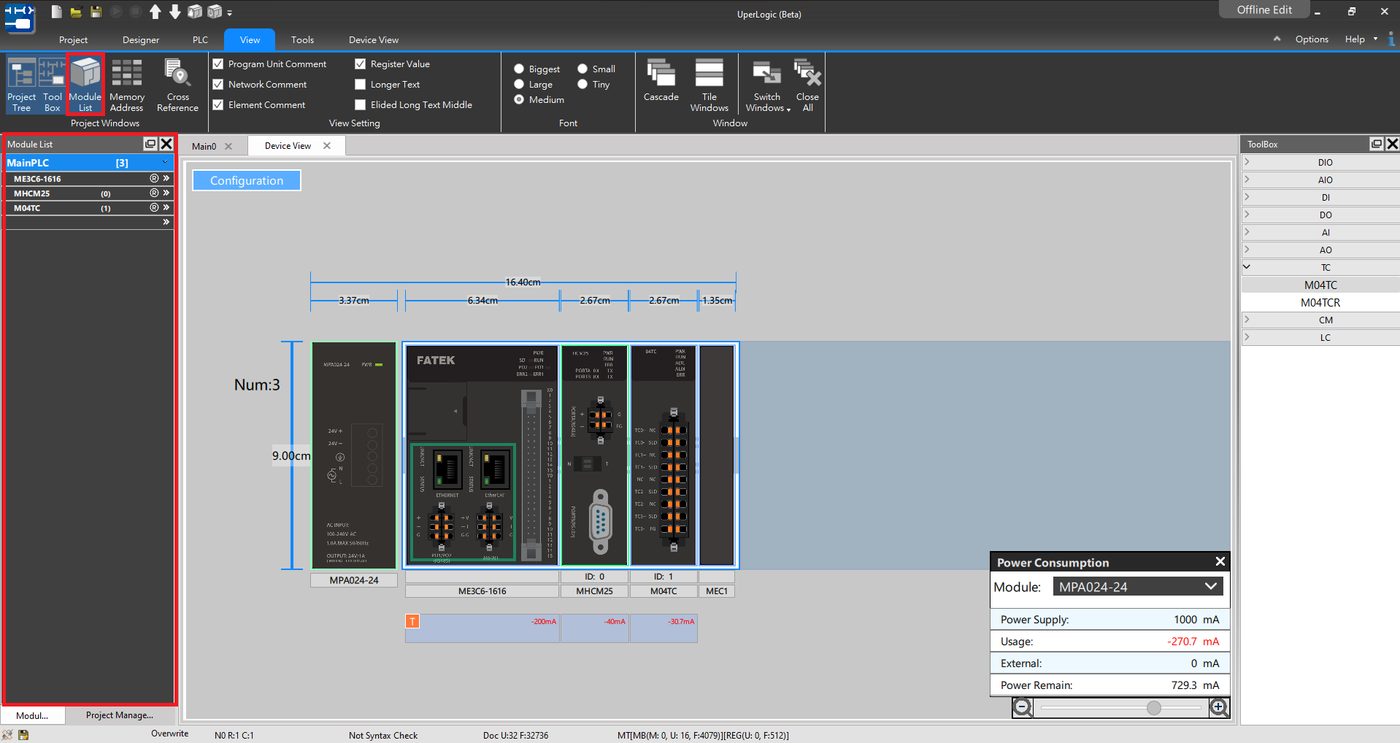
Fig. 19: Module List
Please refer to Section 10-2 for detailed description.
3-5-4 Memory Address
When there are too many components used in the project, it is impossible for the user to fully remember which components or functions use which resources, but through this function, the user can clearly see which registers are used and the corresponding registers; therefore, users can plan the resources in the project more efficiently.
As shown in the figure below, red represents the used registers, and green represents the unused registers. Double-click the list item with the left mouse button to open the corresponding function window.
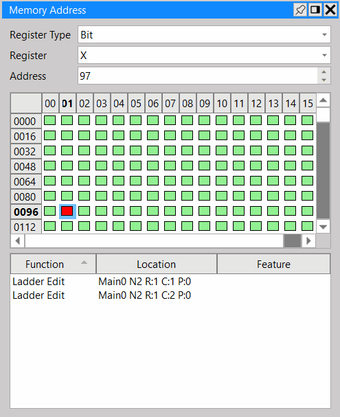
Fig. 20: Memory Address
3-5-5 Cross Reference
Through this function, users can quickly query the location, characteristics, functions and other information of registers or tags, and use the filtering function to further search for registers or tags with specific conditions. Double-click the list item with the left mouse button to open the corresponding function window.
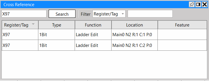
Fig. 21: Cross Reference
3-6 Webpage Configuration Management
In addition to displaying the window list currently opened, the user may also open the designated window or execute the arraying. When opening several windows, the user may arrange the display windows according to personal operating habitude.
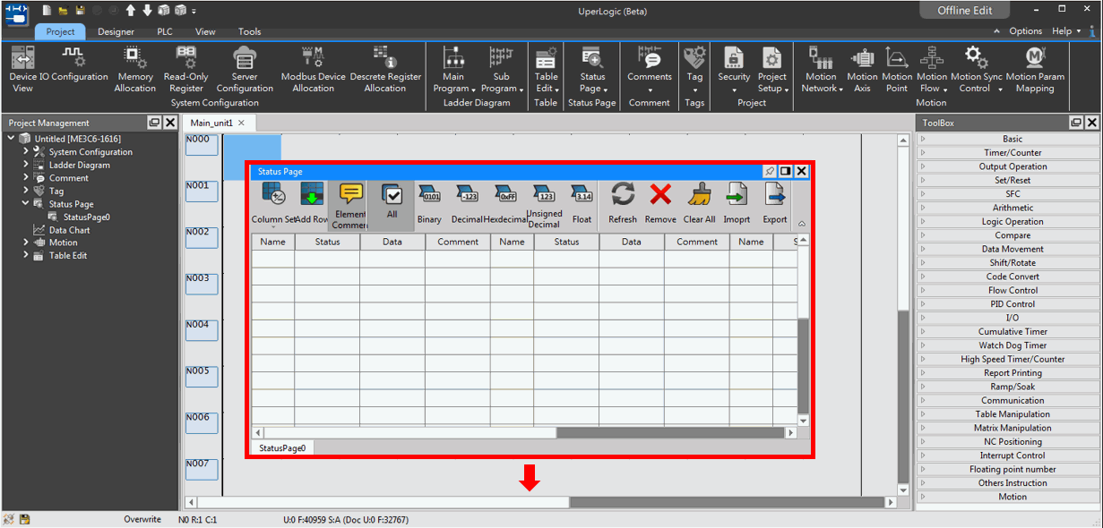
Fig. 22: Webpage management
For example, the user may drag the window of the opened monitoring page to the desired position, release the mouse and then the user will be allowed to change the window arraying pattern.
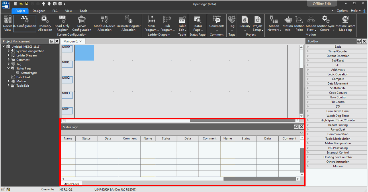
Fig. 23: Changing window arraying pattern
3-7 Quick key
Click [Project] →[Project] → [Quick Key] to view the shortcut keys provided, and also allow users to define familiar quick keys.
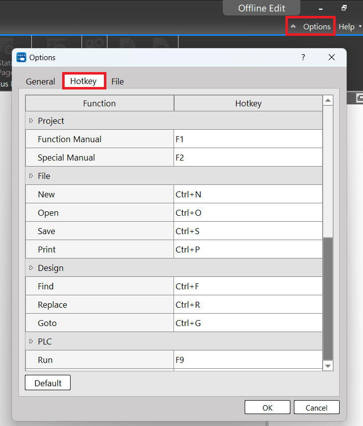
Fig. 24: Quick Key
|
Type |
Function |
Quick key |
|
Project |
Function Manual |
“F1” |
|
Special Manual |
“F2” |
|
|
File |
New |
Ctrl+N |
|
Open |
Ctrl+O |
|
|
Save |
Ctrl+S |
|
|
|
Ctrl+P |
|
|
Design |
Find |
Ctrl+F |
|
Replace |
Ctrl+R |
|
|
Goto |
Ctrl+G |
|
|
Ladder |
||
|
PLC |
Run |
F9 |
|
Stop |
Ctrl+F9 |
|
|
Trial Run |
F10 |
|
|
Discard Change |
Shift+F10 |
|
|
Upload |
F11 |
|
|
Download |
Ctrl+F11 |
|
|
Offline Editing |
Ctrl+F12 |
|
|
Online Monitoring |
F12 |
|
|
Online Editing |
Shift+F12 |
|
|
Other |
Syntax Check |
F8 |
|
Register Content |
F7 |
|
|
Options |
Ctrl+F8 |
|
|
Ribbon Collapse |
Ctrl+F1 |
Table 11: Quick key list
Tip: press ← → to switch chapters, Ctrl+K to search