Test Run
The Test Run is the motion control function specially designed for UperLogic and it belongs to built-in features. To run the Motion control with M-PLC Controller, it can be achieved with the following three methods: 1) Ladder control; 2) Motion Flow; and 3) Test Run. When using this product for the first time, the Test Run function is the quickest, most convenient and easiest method because it allows the user to conduct the Servo operation test without the need of writing any line of the PLC Ladder program and Motion Flow control process.
13-1 Starting Test Run
Users can view the servo test run through PLC > Motion Diagram > Servo Test Run at the top, or right-click the motion link setting in the project management on the left.
Note: You need to enter the online monitoring first and execute the PLC before you can execute this function.
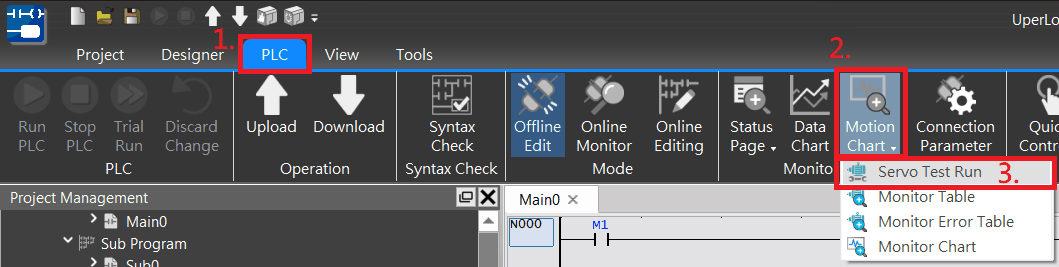
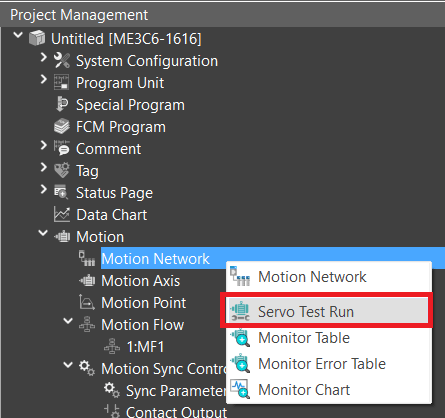
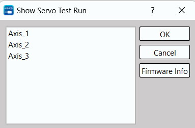
After clicking, select the axis to be tested, and press OK to perform test run control.
13-2 Description of Motion Test Run
The UperLogic test run allows the user to do running tests without editing any Ladder and motion flows. It provides users with three control methods: Position Control, Speed Control, and Torque Control. Each control will be described in subsequent chapters.
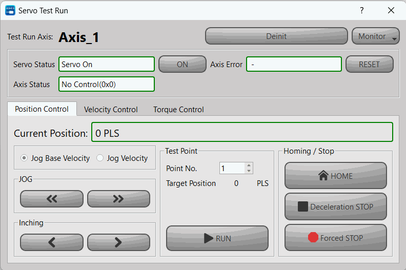
After turning on the test run function, the user must first click Initialization > Servo ON, and then the corresponding control test can be carried out after no abnormalities are found.
Note: The test run function can only be executed when the EtherCAT connection is normal and enabled (Servo on).
|
Introduction of Motion Test Run Basic Function |
|
|
Function |
Description |
|
Test Run Axis |
Display the name of current test run axis. |
|
Initialize&Deinitialize |
After clicking, it will be possible to initialize or deinitialize the axis currently in test run. |
|
Monitor |
Provide shortcut buttons for monitoring tables and monitoring graphs for users to monitor. Users can also find monitoring tables and monitoring graphs through the motion graph on the top or the project management on the left. Note: Users can refer to the chapters of Watch Table and Watch Graph for details. |
|
Servo Status (ON/OFF) |
The current status of the axis will be provided in the green box, and the user can control it through the right button. |
|
Axis Error |
The error information of the current axis will be provided in the green box. If “–“ is displayed, there is no error, and the user can reset the error through the “Reset” button on the right. |
|
Axis Status |
The status information of the current axis will be provided in the green box. |
|
Position Control |
Provide users with functional tests such as JOG, movement point and HOME return, which will be introduced in detail in subsequent chapters. Note: Motion points can only perform single-axis motion control, and cannot perform tests such as linear or arc interpolation. |
|
Speed Control |
It provides users with speed control, which will be introduced in detail in subsequent chapters. |
|
Torque Control |
It provides users with torque control, which will be introduced in detail in subsequent chapters. |
13-3 Description of Test Run Position Control
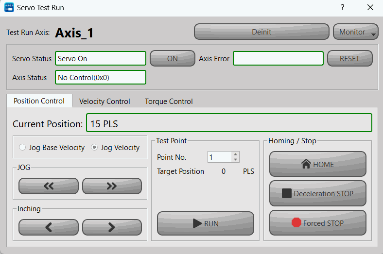
The screen of the position control for trial run is as shown in the figure below. The position control provides a total of three control methods: “JOG”, “Test Point” and “HOME Return”, which will be explained one by one below.
-
- JOG Fintion Description
The control of the JOG mode is on the left side of the position control, and the user can perform forward and backward tests by selecting different modes, and view it from the current position.
|
Mode Collocation |
Description |
|
JOG Base Speed & JOG |
After clicking, it will move at the JOG start speed set by the motion axis until the user releases it, and the servo operation will stop immediately. (Same as JOG mode 0) |
|
JOG Base Speed & JOG |
After clicking, it will move at the JOG start speed set by the motion axis until the JOG distance set by the motion axis is executed, and the servo operation will be stopped immediately. (Same as JOG mode 1) |
|
JOG Speed & JOG |
After clicking, it will move forward from the JOG start speed set by the motion axis, and accelerate to the JOG speed set by the motion axis with the JOG acceleration set by the motion axis, until the user releases it, and decelerate to the JOG deceleration set by the motion axis After the set JOG start speed, stop the servo operation immediately. |
|
JOG Speed & JOG |
After clicking, it will advance from the JOG start speed set by the motion axis, and accelerate to the JOG speed set by the motion axis with the JOG acceleration set by the motion axis, until the JOG distance set by the motion axis is executed, and decelerate with the JOG set by the motion axis. After the speed decreases to the JOG start speed set by the motion axis, the servo operation will stop immediately. (Same as JOG mode 3) |
-
- Test Point Function Description
Test Point provides the user with a test point table to see if the setting is correct. Before the test run, the user must first set the corresponding test point in the motion point setting, and then the test run can be performed.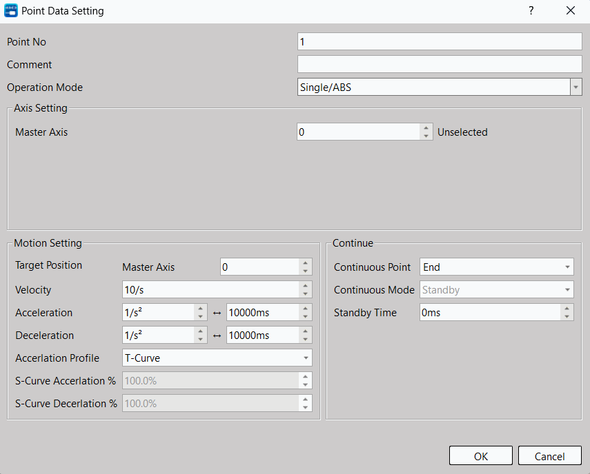
Operation Mode:
During the test run, only single-axis motion control is provided, and other controls such as linear or arc interpolation cannot be performed.
Axis Setting (Master Axis): To select the same axis No. as in the test run.
Motion Setting: Select the target position to be moved, as well as the axis speed and acceleration and deceleration, the initial speed will be the same as the motion axis setting.
Continue: Set whether there is a need to continue to the next point.
Users can test according to the above settings, or refer to the chapter of movement points for more details of the settings.
-
- HOME Return Function Description
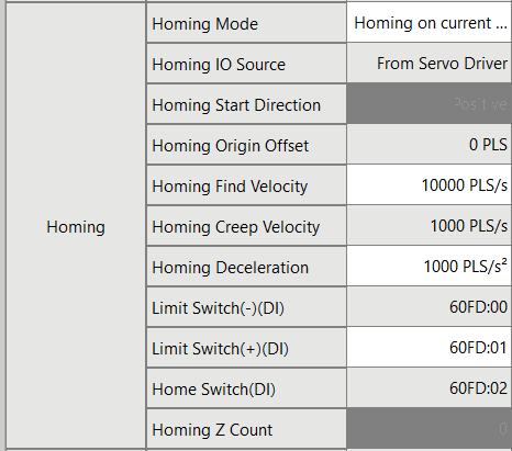
Provide the user with the test of homing, the operation mode is the same as the homing set by the motion axis. When the user does not set the origin, the motor will continue to run. At this time, the function of HOME return can be stopped through the function of deceleration and stop. If an abnormality is about to occur, the motor can also be stopped by forced stop.
13-4 Description of Test Run Velocity Control
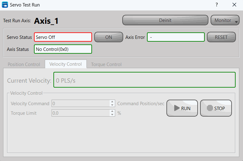
The screen of the test run velocity control is as shown in the figure below. In the test velocity mode, please input the velocity command and torque limit first. After starting, the motor will quickly reach the velocity set by the velocity command, and keep running at the same velocity until the user stops or the torque limit is exceeded.
13-5 Description of Test Run Torque Control
The screen of the test run torque control is as shown in the figure below. In the test torque mode, please input the torque command and speed limit first. After starting, the motor will quickly reach the velocity set by the speed command, and keep running at the same velocity until the user stops or exceeds the speed limit.
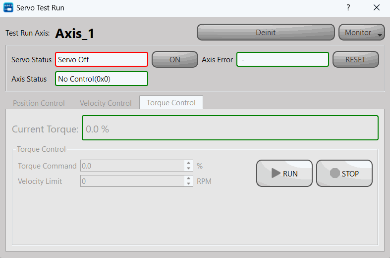
Note: In order to avoid accidents, when the load is not increased, do not set the torque command too large, and set a velocity limit within a safe range, so as to avoid the machine from not reaching the corresponding torque because there is no load, and then continue to accelerate, resulting in errors.
Tip: press ← → to switch chapters, Ctrl+K to search