Motion Example Application
19-1 Interrupt Constant Feed
Background
The grinding machine is a common grinding tool, which uses the grinding wheel to grind or cut the surface of the material to be processed when it rotates at a high speed, so as to achieve the purpose of processing and dressing.
The grinding machine is mainly composed of motor, grinding wheel, grinding wheel support, support arm, protective cover and other components. The grinding wheel is the most critical part of the grinding machine, and its material, shape, size and abrasive grains will affect the processing effect and safety performance of the grinding machine.
Grinding machines are widely used, for example, in metal processing, wood processing, glass processing, ceramic processing, stone processing, rubber processing and other industries. If the grinding wheel needs to be replaced, it needs to be replaced from a fixed angle due to the fixing method of the grinding wheel; therefore, the interrupt constant angle function will be used. When the stop button is pressed, the grinding wheel will decelerate and stop according to the set deceleration and stop at the specified angle.
The case is the control situation that needs to be used when simulating the control of the grinding machine.
The structure of this case is as follows:
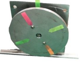
Use the disc to simulate the mechanism of the grinding wheel (high inertia), and use the note paper as a positioning aid:
|
|
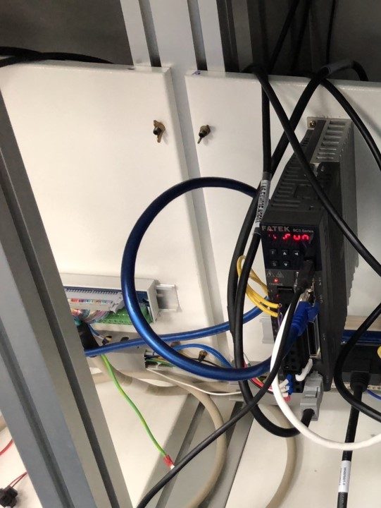
Connect the driver of the servo motor and use Ether Cat communication to communicate with M PLC:
|
|
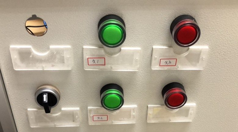
As a button switch for cutting speed and controlling the rotation and stopping of the disc at a specific angle, X1 is used for rotation or stop, X2 is 3000deg/s, X4 is 15000deg/s, and if neither is used, it is 9000deg/s.
Flow Control
This case consists of 1-axis rotation. By setting different speed controls, the different speeds required to deal with different materials can be simulated, thereby improving the grinding efficiency. After use or when the grinding wheel needs to be replaced, it can stop at a fixed position to For the replacement and maintenance of the subsequent grinding wheel, and because the inertia of the grinding wheel is generally large and the grinding wheel cannot be retracted, it is necessary to decelerate and stop with the set deceleration when stopping, and let the final stop position be the desired position. For the set angle, the direction cannot be reversed during the process.
The schemetic diagram is as follows:
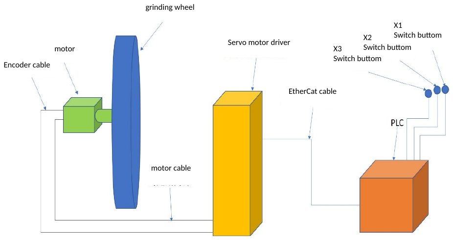
Flow control of the case is as follows:
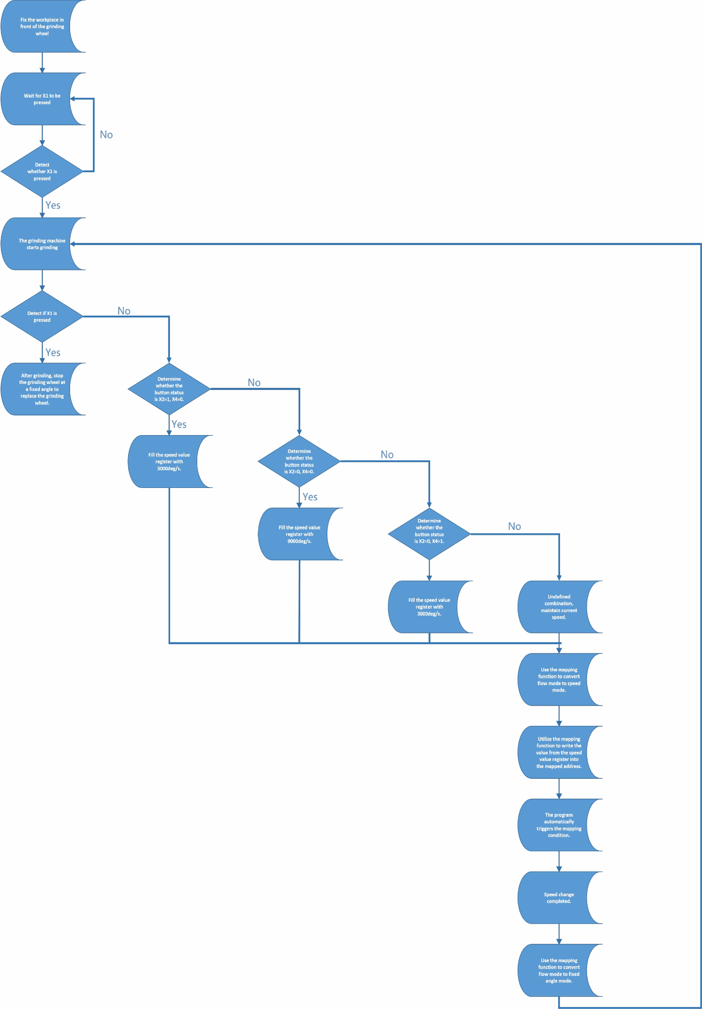
Program Design
This case simulates the need to switch the speed of the grinding wheel due to different material properties of the object to be ground, and it will maintain a fixed speed after switching until the speed is changed or stopped.
Because it needs to be combined with the interrupt fixed angle function, the single-axis speed operation mode of the point table can be used to keep the disc running at a fixed speed.
The Point Table setting is as below:

Fig. 1: Control Point Table of the case
In the program behavior part, the motor needs to be excited after the EtherCat communication is completed, and the command FUN176 MFFlowStart is used to enter the FLOW control process execution point table. The motion control process part is as follows:
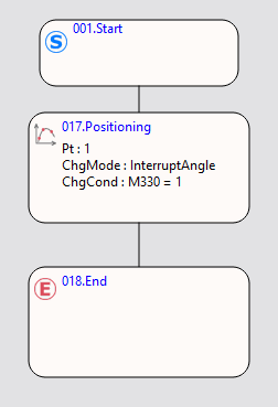
Fig. 2: Flow Chart
Among them, you need to double-click the positioning control box twice to set the change behavior, change the change behavior to “Interrupt Constant Angle”, and write the change condition. This uses M330=1 as the condition,
Because axis 1 is used, check axis 1 to enable it. Part of the changed value must be filled in the fixed angle when stopping. The positioning control setting is as shown in the figure below:
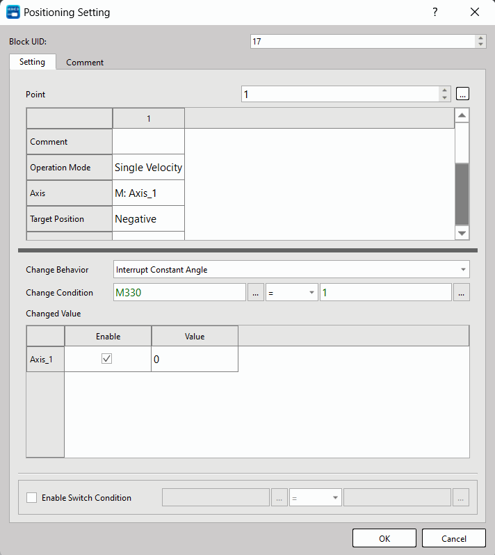
Fig. 3: Position Control setting
After the setting is completed, due to the design requirement, this case can switch the speed during operation. When the speed switch button is triggered, the speed value corresponding to the button combination will be written into the register to be mapped, and the change of the button combination will be proposed. The signal M340 ON is used for the Ladder program that subsequently changes the mode to change the speed value.
After the speed cut button is triggered, the ladder diagram program for writing the speed value and signal is as follows:
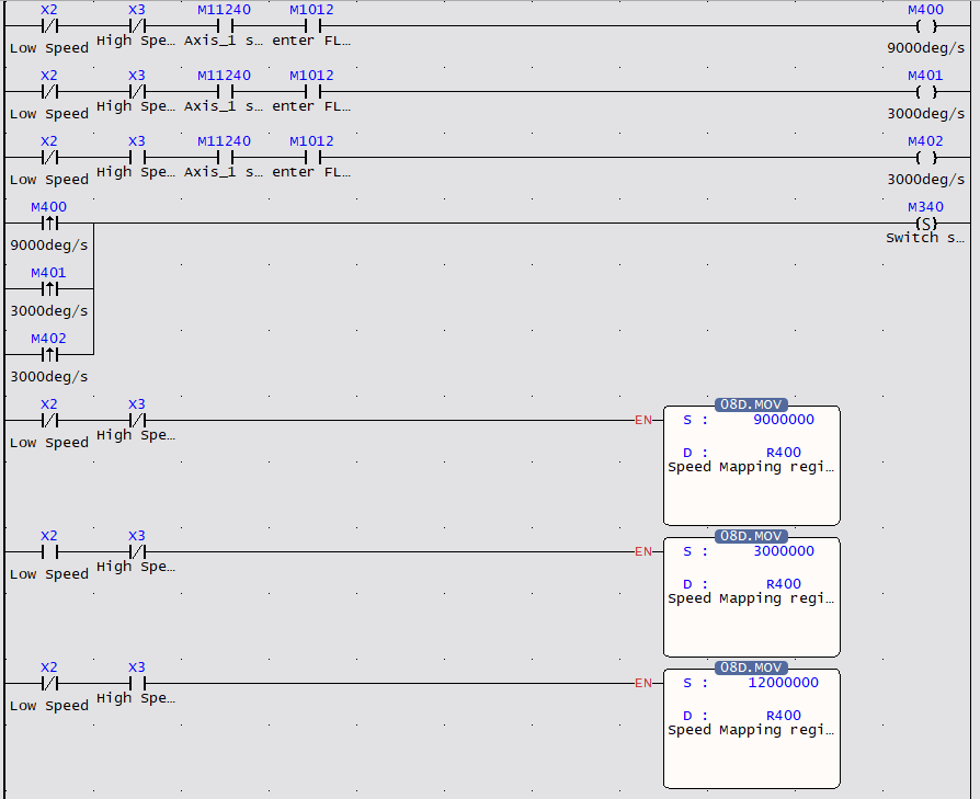
Fig. 4: Ladder diagram of speed triggered switch button
When the button changes, it will automatically change the mode to the speed change mode, and write the value into the value of the changed value through the different speed (variable) of the command FUN181 MFChgTbPrm, and trigger the change condition, that is, M330 ON, and then change Return to the interrupt fixed angle mode, wait for the next change of the shift button or the stop button (triggered by the interrupt fixed angle change button), the Ladder automatically changes the mode to write the speed and then switch back to the fixed angle program part as shown in the figure below:
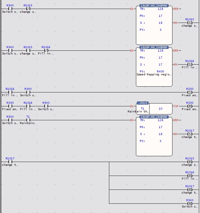
Fig. 5: Ladder diagram for switching modes to write speed
19-2 6-axis Spraying Machine
Mechanic Structure
The 6-axis bus spraying machine is a mechanical reciprocating spraying method that is different from robot automatic spraying and fixed automatic spraying equipment. As the name implies, reciprocating is from left to right, then from right to left (similarly from front to back, from back to front). The paint spraying machine is to fix the spray gun and the spraying machine together, so that reciprocating spraying can be realized. Its main advantages are whether it can track the spraying of the workpiece and improve a certain production efficiency. In addition, it can save part of the paint by allowing the gun to follow the spraying of the workpiece. The second is that it is more flexible and can set the speed repeatedly, and the program is simple, which is much cheaper than the cost of robots and operating costs. The structural analysis 6-axis bus spraying machine of the is as follows:
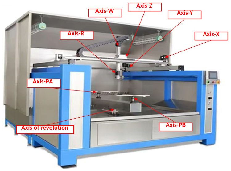
Axis-X:Move left and right Axis-W:Spray gun swings up and down
Axis-Y:Move forward and backward Axis-R:Rotating parallel to the spraying gun
Axis-Z:Move up and down
Axis-PA, PB:Rotating parallel to the product spraying platform
Axis of revolution:Switch product spraying platform
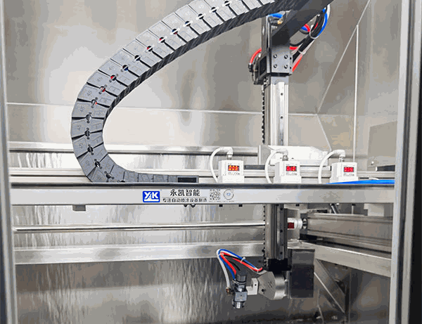
Axis-X of 6-axis reciprocating spraying machine is responsible for the left and right movement of the painting module as shown in the figure below. The Y axis is responsible for the forward and backward movement of the painting module. The Z axis is responsible for the up and down movement of the spray gun. The W axis is responsible for the up and down swing of the spray gun. The R axis is responsible for the rotating parallel to the spraying gun. The rotation on the spraying platform, through the multi-axis coordinated action, can ensure that all surfaces of the product can be painted, and the revolution axis is responsible for switching the worktable, so that when one workbench is painting, the other workbench can carry out the product The loading and unloading work ensures that the painting work can be carried out at all times, which greatly improves the spraying efficiency of the product.
Flow Control
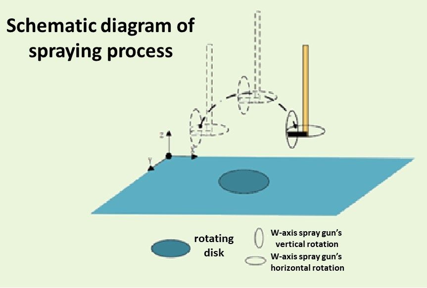
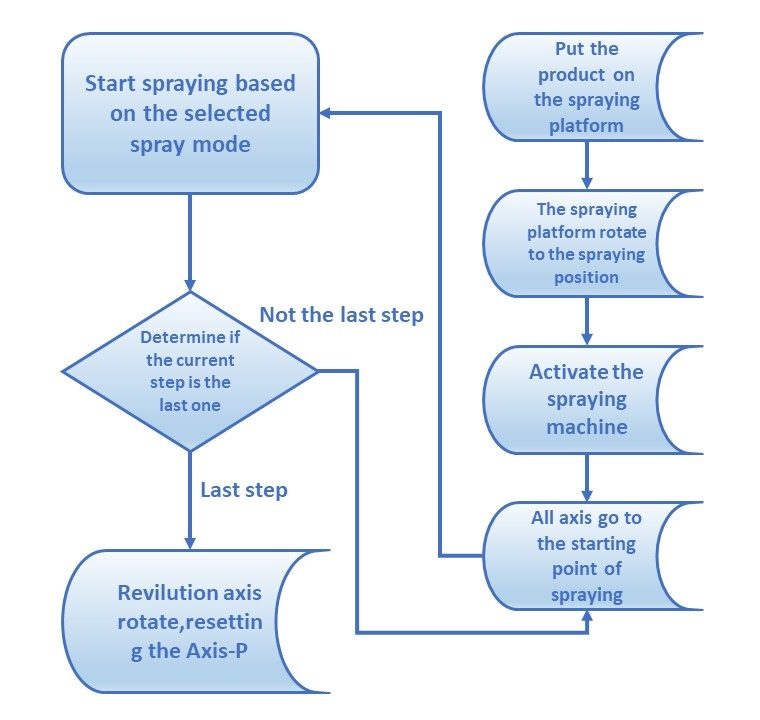
According to the requirements of the production process, the 6-axis spraying machine is mainly composed of X-axis, Y-axis, Z-axis, W-axis, R-axis, P-axis plus a revolution. By setting the cooperation between different axes, the spray gun can move along different The trajectory action constitutes the spraying action process. The schematic diagram of the spraying process of the 6-axis bus spraying machine is as follows.
Control Flow of the 6-axis bus spraying machine is sjown below:
Program Design
Ordinary Plane Spraying
6-axis bus spraying machine can carry out Ordinary Plane Spraying and special-shaped curved surface spraying. Ordinary plane spraying is suitable for products with regular and flat surfaces, such as flat plates in furniture, some flat parts in toys and auto parts; special-shaped Arc surface spraying is usually used for spraying on the surface of arc-shaped parts of automobiles. During the spraying process, the angle between the spray gun and the product surface needs to be kept consistent to ensure the pass rate of the product. Ordinary plane spraying mode is shown in the figure below:
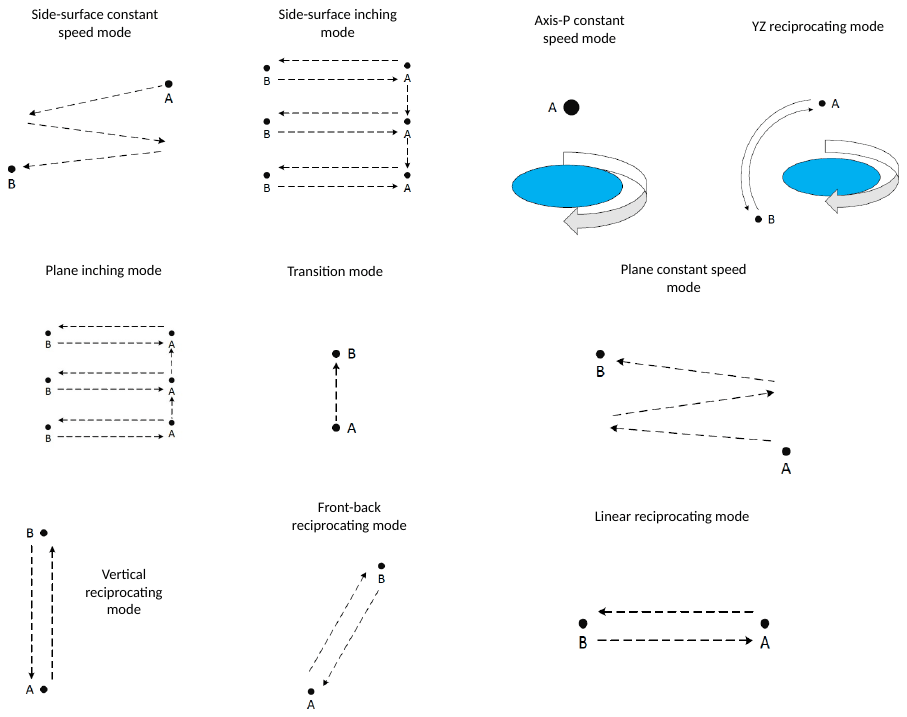
Schematic diagram of ordinary plane spraying mode
The motion trajectory of the 6-axis bus spraying machine is to select the set motion mode, modify the starting point and end point, and set the motion control mode of each step in the form of position control data table. At the same time, the acceleration and deceleration time can be set separately. The acceleration and deceleration mode can also be set to S-shaped acceleration and deceleration, and the speed of each step can also be modified independently; in this way, the action coordination of 60 steps can be realized, which further meets the process requirements of product spraying. The motion control point table of the 6-axis bus spraying machine is shown in Figure 1, and the setting program is shown in Figure 2
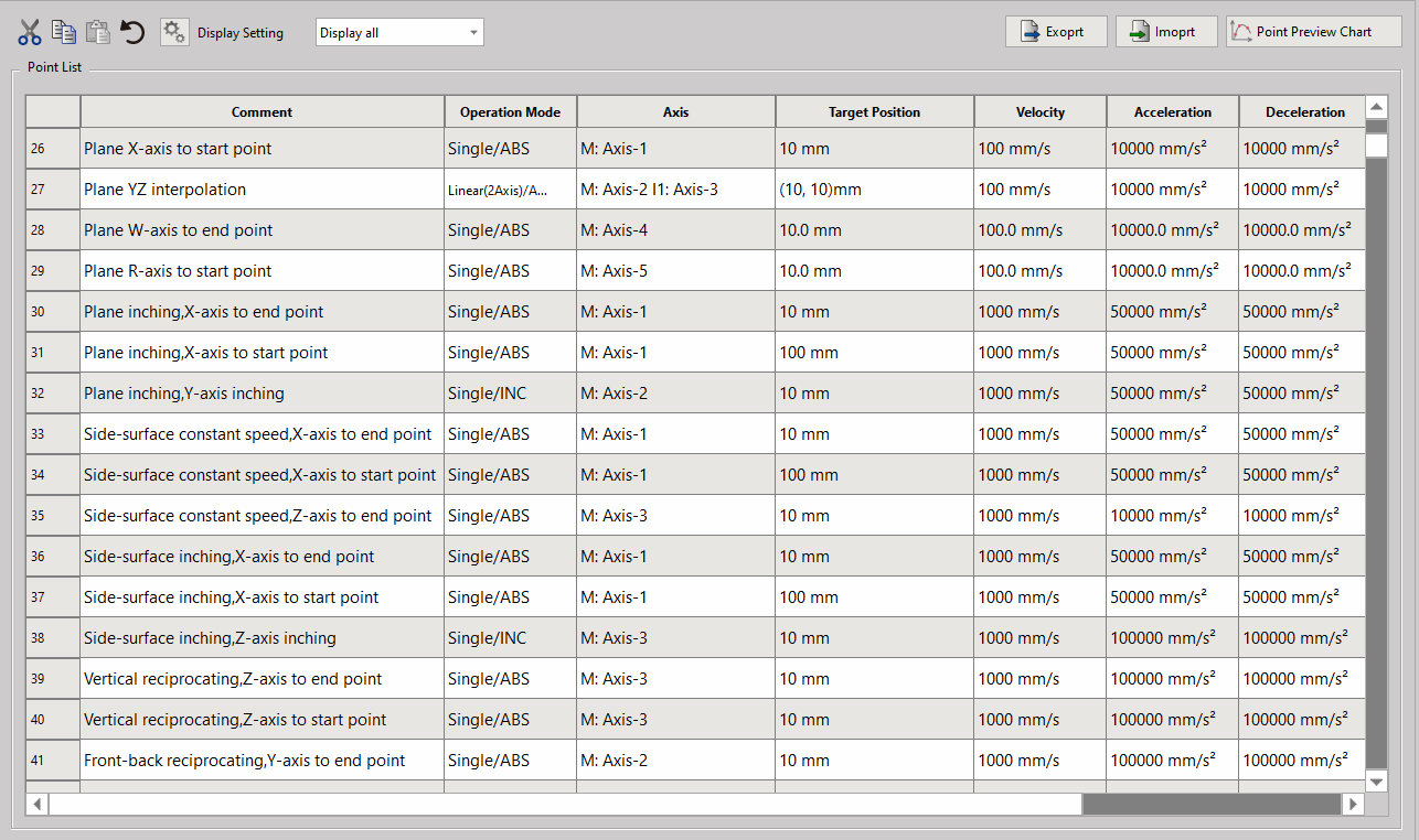
Fig. 1: Table of motion control points of 6-axis bus spraying machine
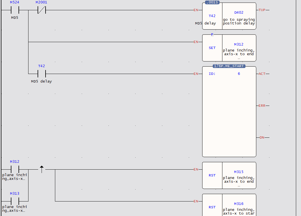
Fig. 2: Part of the program of the motion control trajectory of the 6-axis bus spraying machine
Special-shaped Curved Surface Spraying
The special-shaped curved surface spraying needs to determine the spraying mode according to the size and placement of the product. There are X, Y axis arc R axis follow, X, Z axis arc W axis follow, Y, Z axis arc W axis follow 3 arc mode It can be selected by customers, and the speed of action and the size of the arc can be adjusted. According to the customer’s product requirements, choose to walk the arc or the arc surface, so as to meet the customer’s spraying process requirements. Figure 4-8 shows the schematic diagram of the special-shaped curved surface spraying mode.
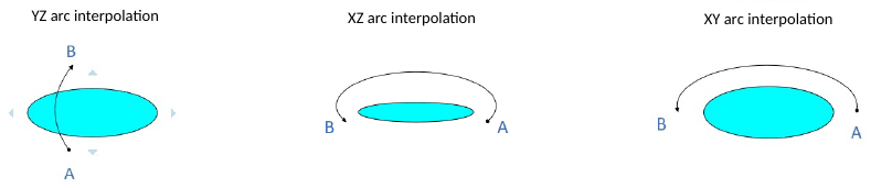
Fig. 3: Schematic diagram of spraying mode on special-shaped curved surface
The arc or arc spraying trajectory of the 6-axis bus spraying machine is mainly determined by selecting the preset position control table, setting the passing point, starting point, end point and speed of the trajectory on the host computer operation interface, and saving these data in the HMI downloads all motion trajectory data to PLC when actions are required, and PLC then performs spraying process actions according to the order of the trajectory selected by the steps. The motion trajectory preset table of the 6-axis bus spraying machine is shown in Figure 3, and the trajectory setting table is shown in Figure 4.
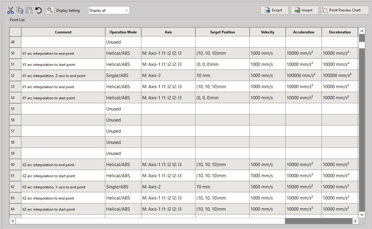
Fig. 4: Motion track preset table of 6-axis bus spraying machine
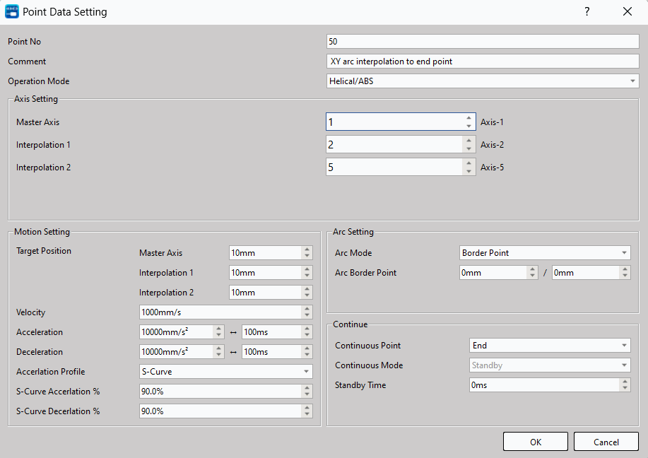
Fig. 5: Motion track setting form of 6-axis bus spraying machine
After the 6-axis bus spraying machine is started, it operates according to the set steps. After completing one step, it reads the data of the next step, and performs the next step according to the set data. When the program runs and reads the next step without setting the action, then Indicates that the spraying action of the current product has been completed, execute the revolution to rotate the current spraying platform, and restart the spraying work of the next product from the first step. The step reading program of the 6-axis bus spraying machine is as shown in the figure below.
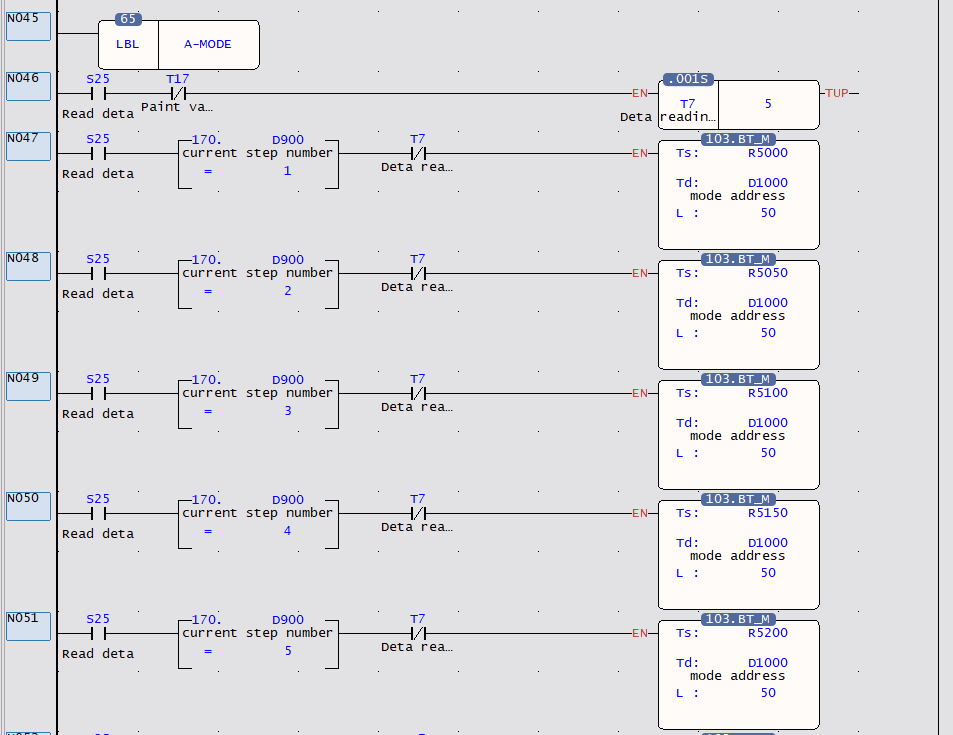
6-axis bus spraying machine steps to read part of the program
Spiral Interpolation Control
In the spraying process of special-shaped curved surface products, the angle of the spray gun and the product needs to be consistent. Through the spiral interpolation algorithm, the two axes can draw arcs, and the third axis can follow the linear interpolation, so as to realize the circular arc. During the process, swing the spray gun from time to time so that the angle of the spray gun is consistent with the product. The helical interpolation trajectory demonstration is shown in Figure 5, and the spiral interpolation program control of the 6-axis bus s is shown in Figure 6。
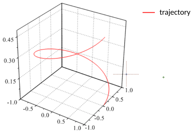
Fig 6: Demonstration of spiral interpolation trajectory
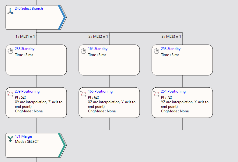
Fig. 6-2: 6-axis bus spiral interpolation program control
3D Arc Interpolation Control
In the spraying process of special-shaped curved surface products, some products cannot be placed flat on the spraying platform, and the placement position will have an angle with the spraying platform. At this time, the spiral interpolation cannot meet the current process requirements. It can make the action trajectory of the spray gun the same as the shape of the product, so as to meet the customer’s spraying process requirements. The 3-axis space circular interpolation trajectory demonstration is shown in Figure 7, and the 6-axis bus 3-axis space arc interpolation trajectory is shown in Figure 8.
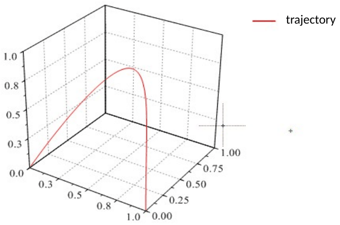
Fig. 7: Demonstration of axis space arc interpolation trajectory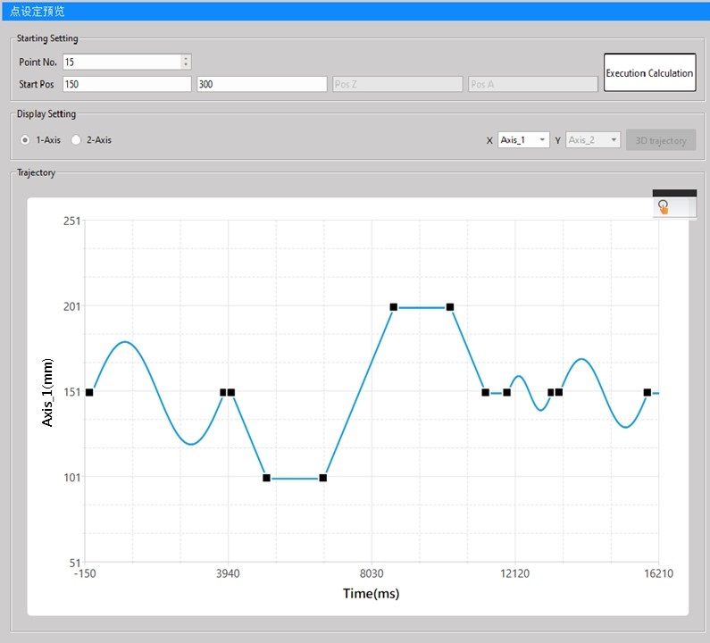
Fig. 8: 6-axis bus 3-axis space arc interpolation trajectory
19-3 VFFS Vertical Form Fill Seal machine
【Example 1】VFFS machine
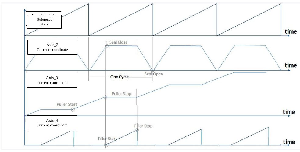
With E-CAM, use the reference axis to synchronously control the three axes of
A. Filling Machine/B. Drawing Machine/C. Sealing machine
In the following sample program, the axis numbers of Reference Axis 1/Reference Axis 2/Filling Machine/Drawing Machine/Sealing Machine correspond to Axis 5/Axis 1/Axis 4/Axis 3/Axis 2.
#In this example, two virtual axes are used as the motion curve of the reference axis, in order to demonstrate more motion control actions, so that users can be familiar with more motion control. After familiarizing with this example, users can The program of the synchronous input axis can be optimized according to the actual use.
Organization diagram
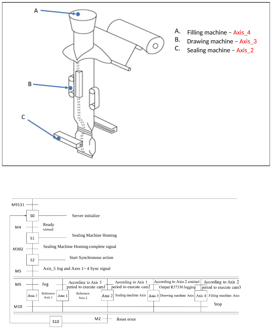
Stepping Ladder Diagram
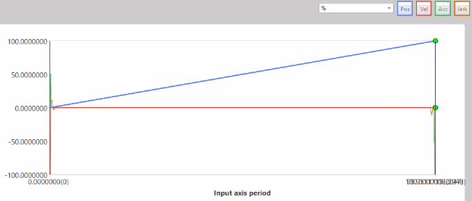
CAM Curve ①
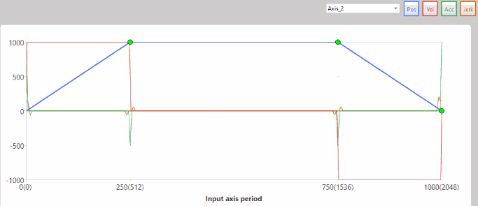
CAM Curve ②
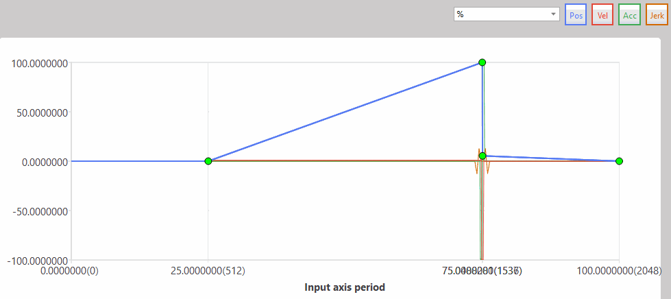
CAM Curve ③
Time Order Chart
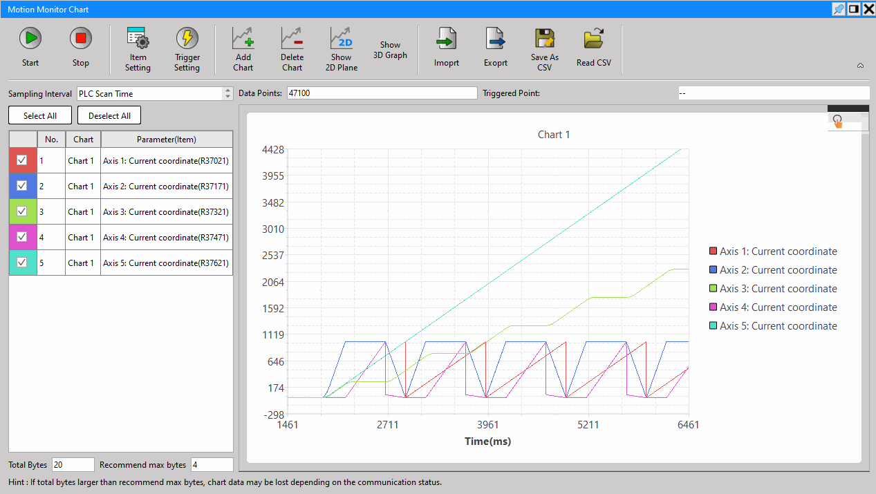
Monitoring chart during actual operation
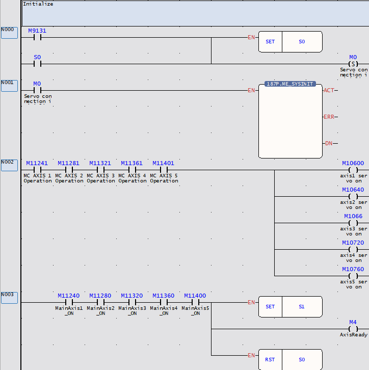
|
Uperlogic |
Description |
|---|---|
|
|
M9131 Initial Pulse Servo connection initialization When initialization is complete, servo control ready signal ON → Axis Servo on Servo on signal feedback All axes are Ready→M4 ON (Axis ready) When each axis alarm occurs M2 Manual→ON clear alarm M3→ON Clea eroor alarm M400→ON Back to initialization #For the definition of special register, please refer to the PLC instruction manual |
|
|
When an axis error occurs, the homing action cannot be performed In this example, the reset I/O signal is output from the PLC, so M10645 coil is required M12 ON→axis 3 starts homing Return to original action completed → M302 ON M5→ON starts motion flow control Axis 5 JOG start → operate according to the JOG parameters set by the motion axis MD: 2, jogging at JOG speed D/R: positive direction (ON) / negative direction (OFF) R37180: Axis 2 synchronous contact R37180=1, axis 3 JOG start M5→ON motion flow control Start When an error occurs on each axis, enter the error clearing step. |
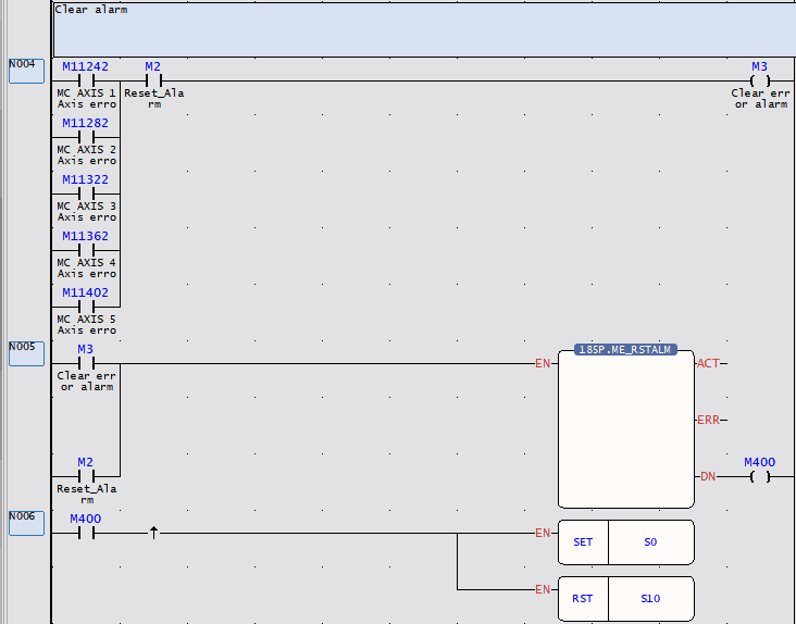
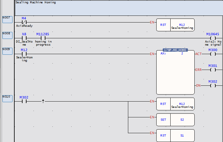
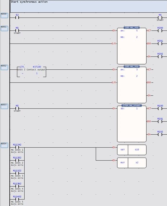
|
Uperlogic |
Description |
|---|---|
|
|
Flow start → enter parallel branch After entering each branch, confirm the servo ready signal Start synchronous action (For synchronization settings, please refer to the instructions on the next page) After the synchronous action is enabled, the flow stops until the user flow M10 (The synchronous action will be canceled when the flow ends) |
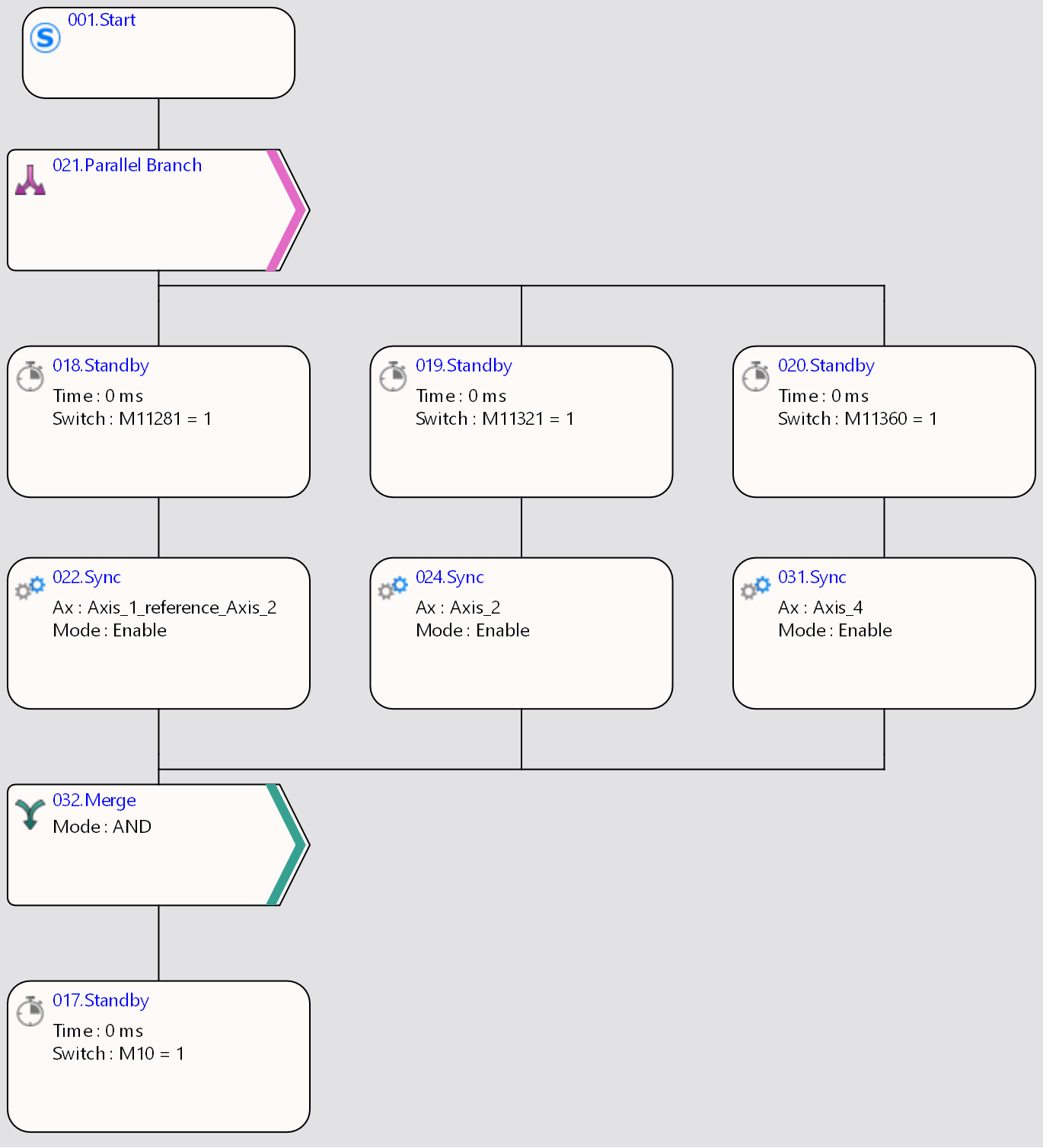
Sync settings and CAM settings
After adding the “Synchronize” function block in the motion flow, it is necessary to perform CAM settings on this function block so that axes 1, 2, and 4 can correctly follow the master axis coordinates to perform synchronous E-CAM motion. For detailed steps, please refer to the following:
- Setting Funtion Block
Left click on the sync block → open sync settings
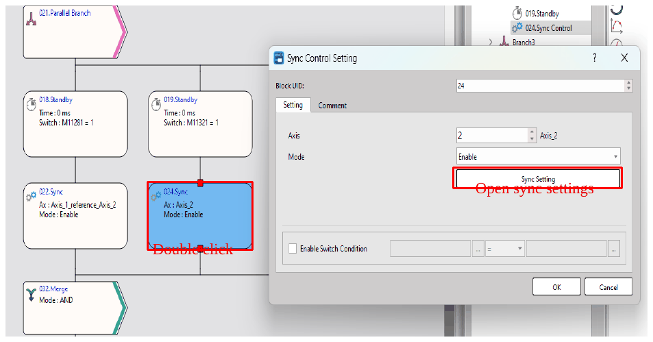
After enabling the synchronization setting, the setting window will appear as follows:
Take the sealed axis of axis 2 as an example, if the axis 2 synchronization setting is turned on, you can see that the “output axis” is axis 2.
In addition, the input coordinates of the package axis refer to “reference axis 2”, so in “select input axis”, select “command position axis 1_reference axis 2”
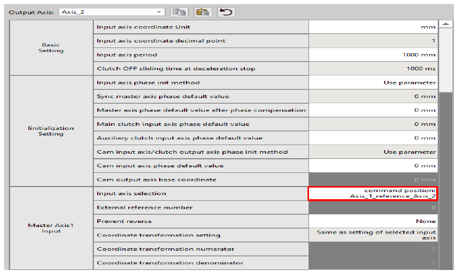
After setting the input and output axes, then set the “cam data number”, and the axis can move according to the cam stroke of this number.
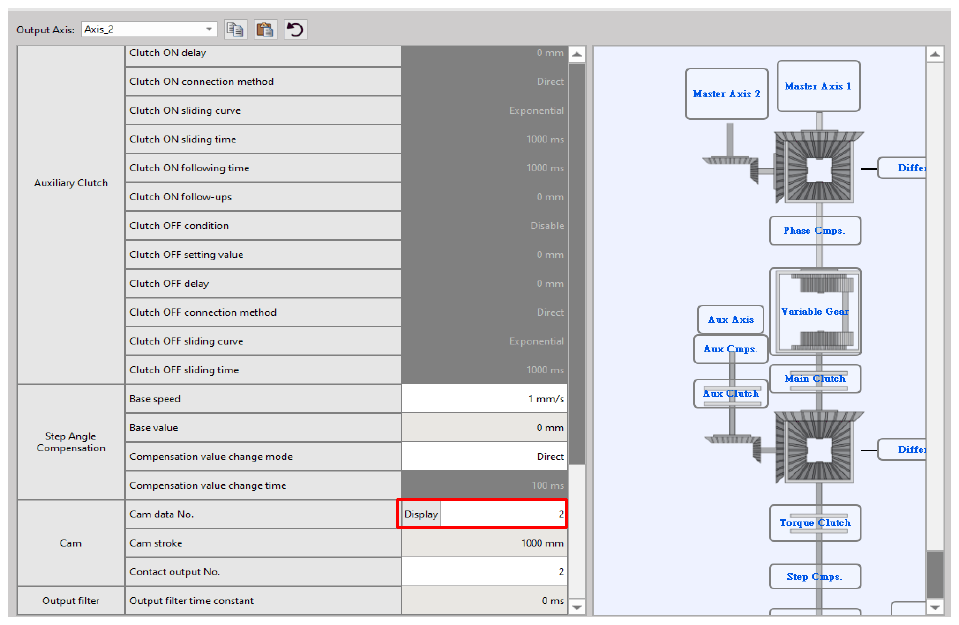
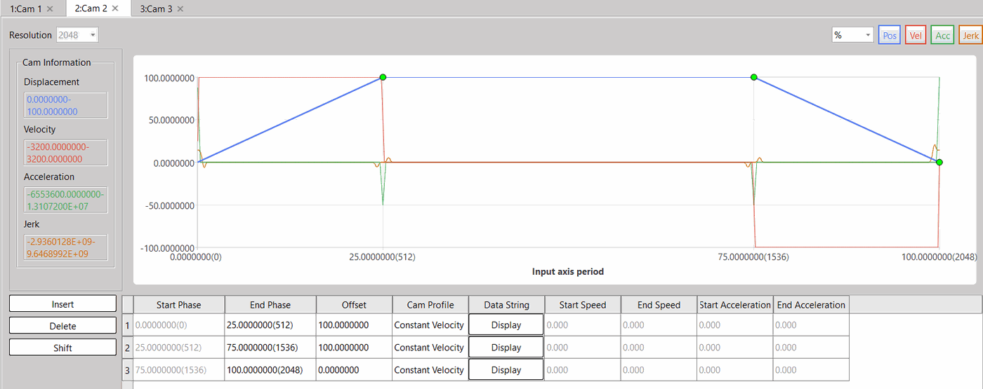
Take the package axis of axis 2 as an example, when I set the Cam numbered 2, the stroke is as shown in the figure below:
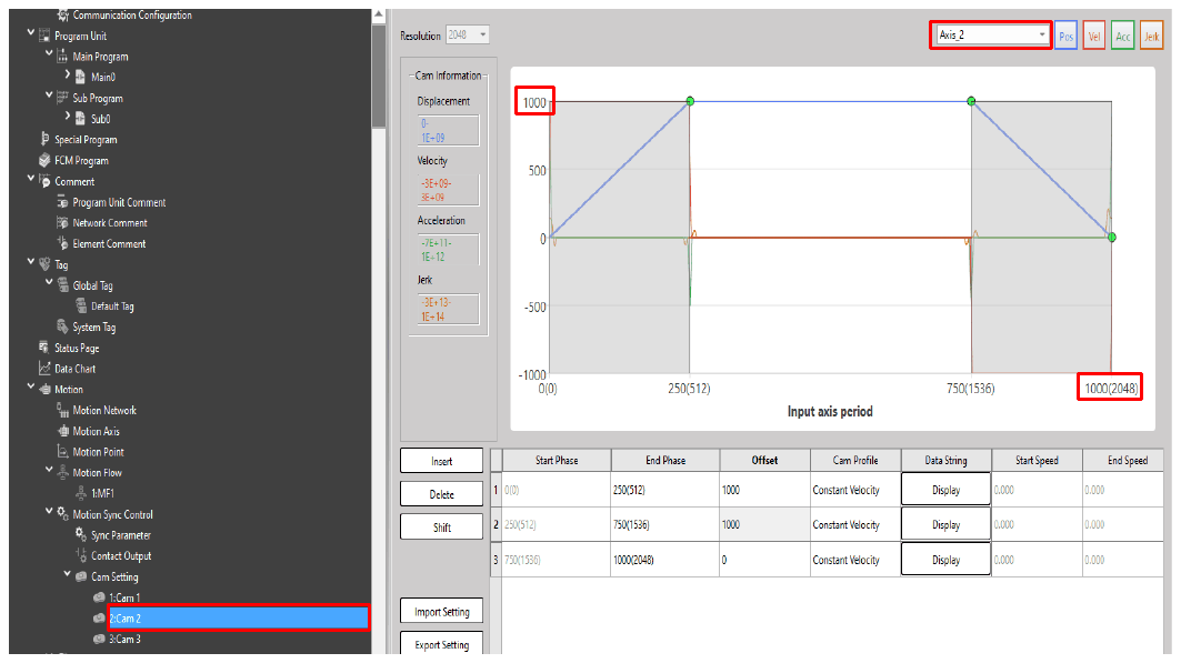
The cam curve of the display axis 2 packaging axis will move according to this stroke, the “1000” of the Y axis will be changed according to the “cam stroke” in the synchronization parameter, and the “1000(2048)” of the X axis will be changed according to the “input axis” in the synchronization parameter cycle to make changes. This example shows that the output axis “axis 2” will follow this cam curve, and when the input axis “axis 1” reaches the position of 1000mm, the position of axis 2 will change according to this curve.
The action trajectory reference monitoring diagram is as follows: 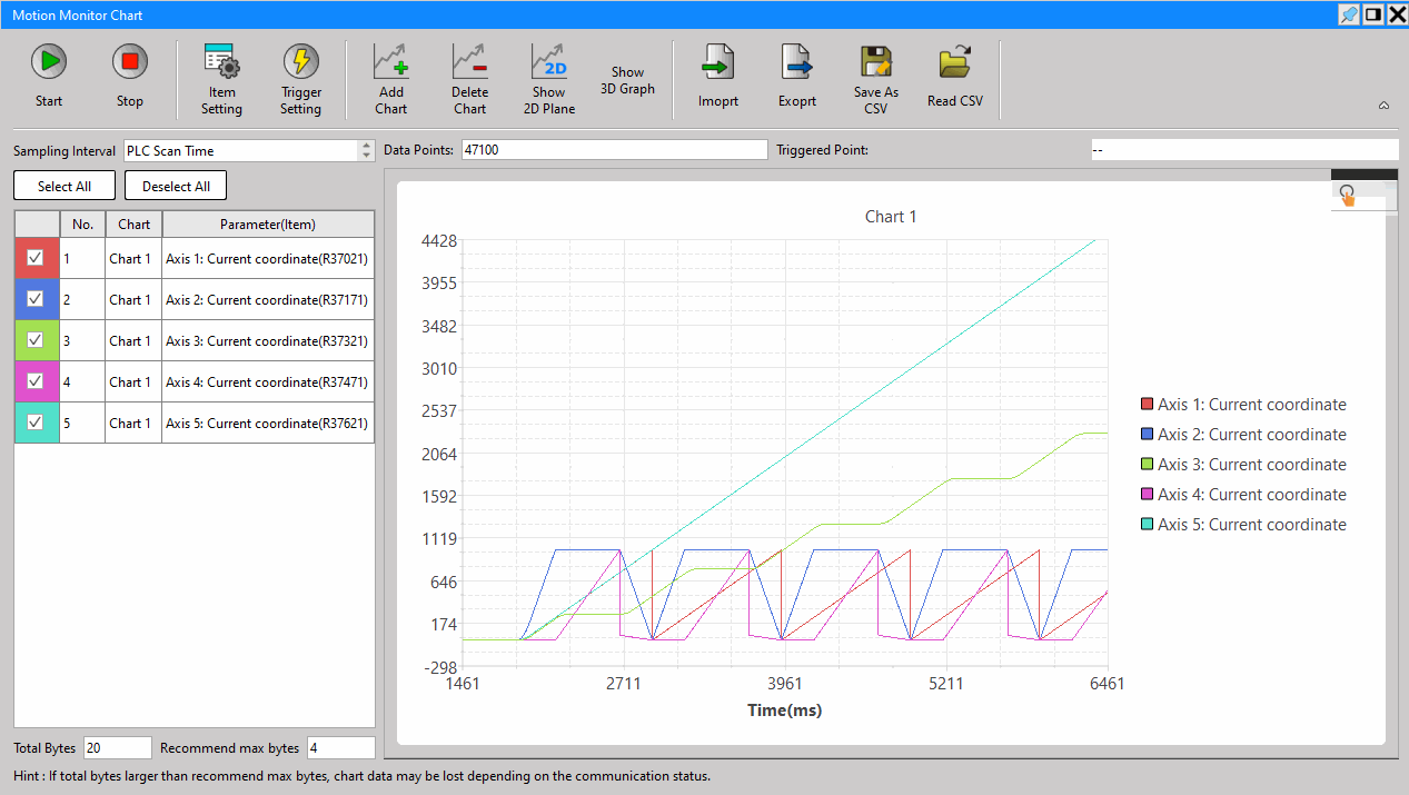
The same is true for other axes, when the synchronization and CAM travel of each axis are set
Users can perform cam CAM control synchronously.
- Setting synchronous contact
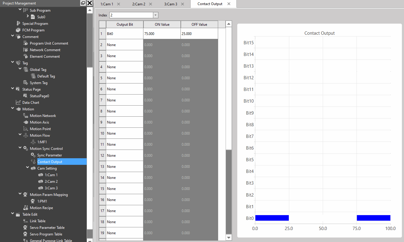
The action of axis 3 needs to be matched with the synchronous contact function of axis 2. Select the synchronous contact number 2 according to the figure below:
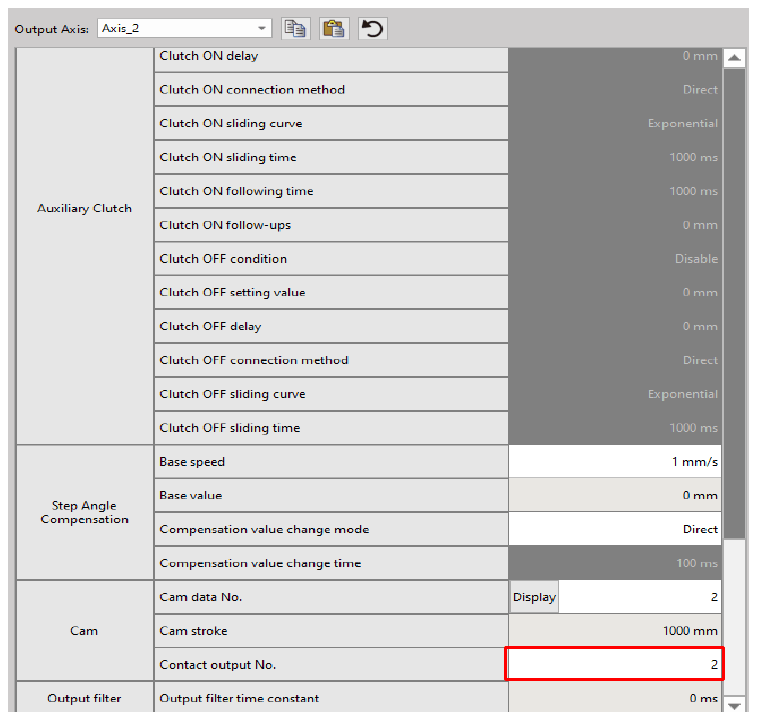
Axis-2 synchronous contact temporary register R37180 will change according to the settings in the figure below, take this figure as an example at the position of 75% of the cam curve R37180=1, 25%
Position R37180=0
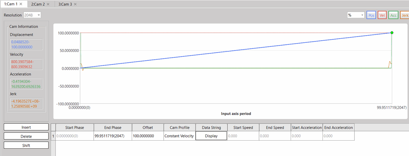
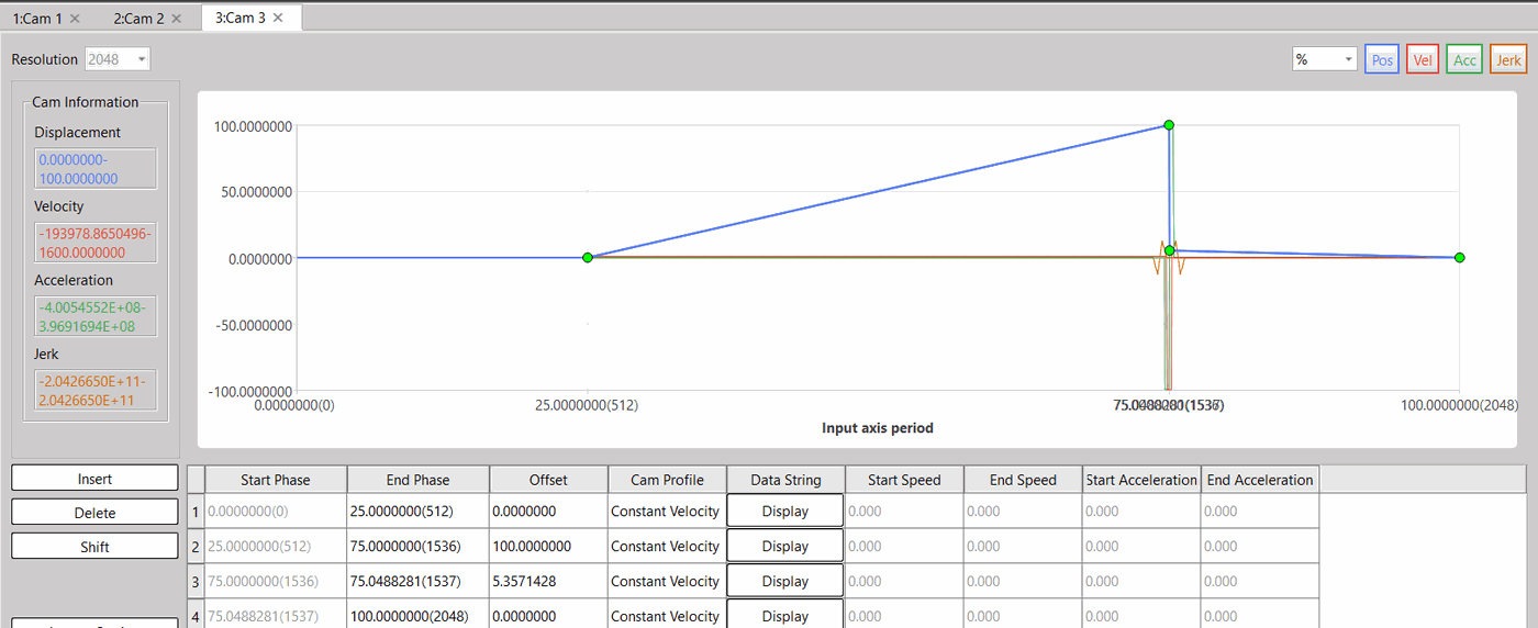
- Setting E-CAM Stroke
The figure below shows the CAM settings of each axis
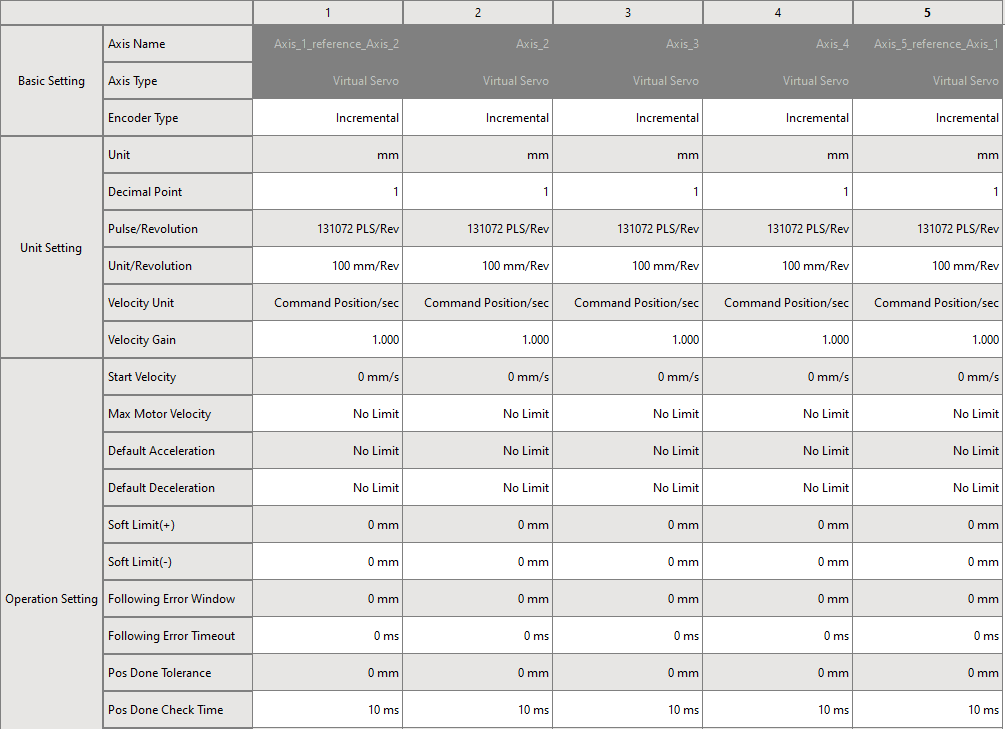
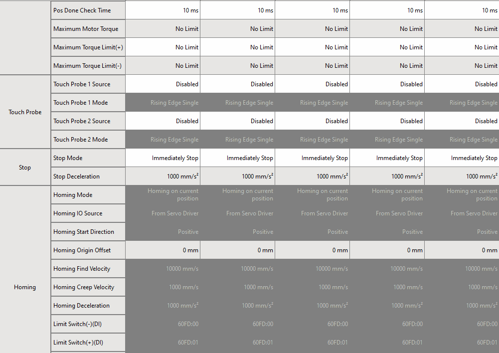
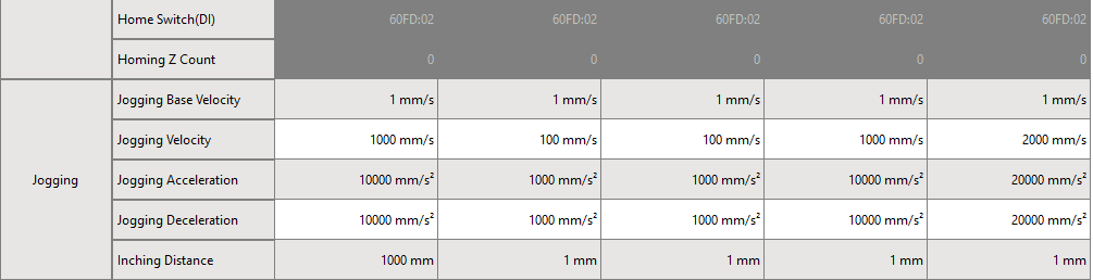
- Motion Axis Setting Reference
Revision History
|
Version |
Date |
Description |
|
V1.0 |
2024/12/23 |
First version |
Tip: press ← → to switch chapters, Ctrl+K to search