5-1 The Format of Function Instructions
Function Instructions of M PLC will be divided into four parts including input control, instruction number/name, operand and function output. The number of input controls, operands, and function outputs of each instruction is different (please refer to the description of each instruction).
|
Ladder Diagram |
|
|
Example 1: Single Input Instruction |
|
|
|
|
|
Example 2: Multiple Input Instruction |
|
|
|
|

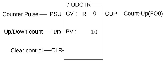
The Format of Function Instructions
5-1-1 Input Control
M PLC has at least one input control for other application commands except for 7 application commands without input control, up to eight. Application instructions are based on the combination of input control signals to determine whether to execute the instruction and what kind of operation to perform. On the software package of UperLogic and when the ladder diagram program is printed out, all the input control and function output terminals of the application instruction symbols are marked with English comment abbreviations to indicate what kind of function control or output the terminal is, so as to facilitate memory and Read, as shown in the above figure 2, the first input is marked "PLS", which means that the counter only counts once when the counting pulse pulse changes from 0→1 (rising edge), and the second input is marked "U/D" on the U meter above the slash Count Up, D at the bottom means count Down, if this input is 1, when the counting pulse PLS comes, the counter value will increase by 1, otherwise, if it is 0, it will decrease by 1, and the third input is marked "CLR", which means clear Clear, that is, when this input is 1, the count value of the counter will be cleared to 0. For the input control comments of other application commands, please refer to the description of each command.
Note: No input control command means that the command needs to be directly connected to the bus, and cannot be connected in series with input control components, and has no functional output. The command itself forms a network. There are 6 non-input control commands such as MCE, SKPE, LBL, RTS, FOR, NEXT, etc., please refer to the description of each command in Chapter 6 and 7.
All input controls of the function instructions should be connected by the corresponding elements, otherwise a syntax error will occur. As shown in example 3 below, the function instruction FUN7 has three inputs and three elements before FUN7. X0, X1, and X2 corresponds to the first input PLS, second input U/D and third input CLR.
|
Ladder Diagram |
|
|
|
|
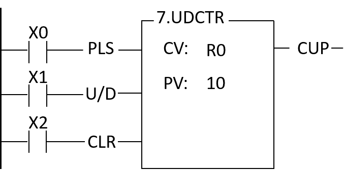
Function instruction of Input Control
5-1-2 Instruction Number and Derivative Instructions
D:Indicates a Double Word (32-bit). The 16-bit word is the basic unit of the registers in M-Series PLC. The data length of R, T and C (except C1024~C1063) registers are 16-bit. If a register with 32-bit data length is required, then it is necessary to combine two consecutive 16-bit registers together such as R1-R0, R3-R2 etc. and those registers are represented by prefix a D letter before register name such as DR0 represents R1-R0 and DR2 represents R3-R2. If you enter DR0 or DWY16 in the monitor mode of FP-08, then a 32-bit long value (R1-R0 or WY32-WY16) will be displayed.
|
B31 |
B16 |
B15 |
B0 |
||
|
DR0 |
=R1─R0 |
R1 |
R0 |
||
|
↑ |
↑ |
||||
|
High Word register Low Word register |
|||||
|
B31 |
B16 |
B15 |
B0 |
||
|
DWY16 |
=WY32–WY16 |
WY32 |
WY16 |
||
|
=Y47~Y16 |
↑ |
↑ |
|||
|
High Word register Low Word register |
|||||
Note 1: In order to differentiate between 16-bit and 32-bit instructions while using the ladder diagram and mnemonic code, we add the postfix letter D after the "Instruction number" to represent 32-bit instructions and the size of their operand are 32-bit. The instruction FUN 11D has a postfix letter D, therefore the source and destination operands need to prefix a letter D as well, such as the augend Sa:R0 is actually Sa=DR0=R1-R0 and Sb=DR2=R3-R2. Please also pay special attention to the length of the other operands except source and destination are only one word whether 16-bit or 32-bit instructions are used.
Note 2: Reading register status at labber Diagram, we can add the prefix letter W before the "Instruction number" to access the register status of consecutive 16 bits, for example, WX0 represent X0~X15, WM32 represent M32~M47, the accessed bit address must be a multiple of 16 bits. For example, WM16 is a legal address, but WM8 is an illegal address.
P:indicates the pulse mode instruction. The instruction will be executed when the status of input control changes from 0 to1 (rising edge). If a postfix letter P is added to the instruction (FUN 15P), the instruction FUN 15P will only be executed when the status of input control signal changes from 0 to 1. The execution of the instruction is in level mode if it does not have a P postfix, this means the instruction will be executed for every scan until the status of input control changes from 1 to 0. In this operation manual, an example of the operation statement of a function instruction is shown below.
- When the operation control “EN”=1 or(P instruction)from 0→1, .........
The first one indicates the execution requirement for non-P instruction (level mode) and the second one indicates the execution requirement for P instruction (pulse mode). The following waveform shows the result (R0) of FUN15 and FUN15P under the same input condition.
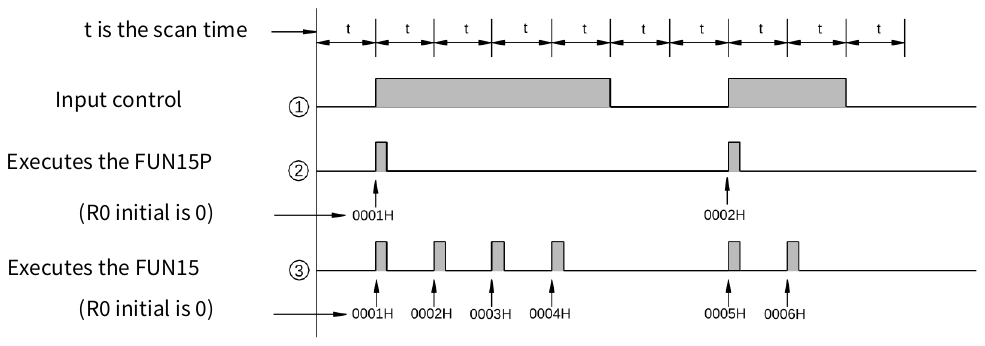
FUN15 R0 of FUN15 and FUN15P under the same input condition
D P:Indicates the instruction is a 32-bit instruction operating with pulse mode.
Note: P instruction is much more time saving than level instruction in program scanning, so user should use P instruction as much as possible.
5-1-3 Operand
The operand is used for data reference and storage. The data of source (S) operand are only for reference and will not be changed by the execution of the instruction. The destination (D) operand is used to store the result of the operation and its data may be changed after the execution of the instruction. The following table illustrates the names and functions of M-Series PLC function instruction’s operands and types of contacts, coils, or registers that can be used as an operand.
- The names and functions of the major operands:
|
Abbreviation |
Name |
Description |
|---|---|---|
|
S |
Source |
The data of source (S) operand are only for reading and reference and will not be changed with the execution of the instruction. If there are more than one source operands, each operand will be identified by the footnote such as Sa and Sb. |
|
D |
Destination |
The destination (D) operand is used to store the result of operation. The original data will be changed after operation. Only the coils and registers which are not write prohibited can be the destination operand. |
|
L |
Length |
Indicates the data size or the length of the table, usually are constants. |
|
N |
Number |
A constant most often used as numbers and times. If there are more than one constant, each constant will be identified by the footnotes such as Na, Nb, Ns, Nd, etc.. |
|
Pr |
Point |
Used to point to a specific a block of data or a specific data or register in a table. Generally, the Pr value can be varied, therefore cannot be constant or input register. |
|
CV |
Current value |
Used in T and C instruction to store the current value of T or C |
|
PV |
Set value |
Used in T and C instructions for reference and comparison |
|
T |
Table |
A combination of a set of consecutive registers forms a table. The basic operation units are word and double word. If there is more than one table, each table will be identified by footnotes such as Ta, Tb, Ts and Td etc.. |
|
M |
Matrix |
A combination of a set of consecutive registers forms a matrix. The basic operation unit is bit. If there is more than one matrix, each matrix will be identified by footnotes such as Ma, Mb, Ms and Md etc.. |
Major operands list
Besides the major operands mentioned above, there are other operands which are used for certain special purposes such as the operand Fr for frequency, ST for stack, QU for Queue etc., please refer to the instruction descriptions for more details.
- The types of the operand and their range: The types of operands for the function instructions are Discrete, Register and Constant.
- Discrete (Digital) Operand:
There is total five function instructions that reference the discrete operand, namely SET, RST, DIFU, DIFD and TOGG. Those five instructions can only be used for operations of Y△△△△ (external output), M△△△△△ (internal and special) and S△△△△ (step) relays. The table shown below indicates the operands and ranges of the five function instructions.
|
Range Operand |
Y |
M |
SM |
S |
|
Y0 ∣ Y255 |
M0 ∣ M1911 |
M1912 ∣ M2001 |
S0 ∣ S999 |
|
|
D |
○ |
○ |
○ |
○ |
Discrete operand ranges list
Symbol "O" indicates the D (Destination operand) can use this type of coils as operands. The "*" sign above the "O" shown in SM column indicates that should exclude the write prohibited relays as operands. Please refer to Chapter 2-3 for introduction of the special relays
- Register Operand:
The major operand for function instructions is register operand. There are two types of register operands: the native registers which already is of Words or Double Words data such as R, T, C. The other is derivative registers (WX, WY, WM, WS) which are formed by discrete bits. The types of registers that can be used as instruction operands and their ranges are all listed in the following table:
|
Range Ope-rand |
WX |
WY |
WM |
WS |
TMR |
CTR |
HR |
IR |
OR |
SR |
ROR |
DR |
K |
XR |
|
WX0 ∣ WX1008 |
WY0 ∣ WY1008 |
WM0 ∣ WM25584 |
WS0 ∣ WS3088 |
T0 ∣ T1023 |
C0 ∣ C1279 |
R0 ∣ R34767 |
R34768 ∣ R34895 |
R35024 ∣ R35151 |
R35280 ∣ R43223 |
R43224 ∣ R47319 |
D0 ∣ D11999 |
16/32-bit |
V,Z P0~P9 |
|
|
S |
○ |
○ |
○ |
○ |
○ |
○ |
○ |
○ |
○ |
○ |
○* |
○ |
○ |
○ |
|
D |
○ |
○ |
○ |
○ |
○ |
○ |
○ |
○* |
○* |
○ |
○ |
|||
|
• • • |
Register operand ranges list
The "○" symbol in the table indicates can apply this kind of data as operand. The "○*" symbol indicates can apply this kind of data except the write prohibited registers as operand. To learn more about write prohibited registers please refer to page 2.4 for introduction of the special register.
When R43224~R47319 are not set to be read only registers, can used as normal registers (read, and write)
Note 1: The registers with a prefix W, such as WX, WY, WM and WS are formed by 16 bits. For example, WX0 means the register is formed by X0(bit 0) ~ X15(bit 15). WY144 means the register is formed by Y144(bit 0) ~ Y159(bit 15). Please note that the discrete number must be the multiple of 16 such as 0, 16, 32, 48….
Note 2: The last register (Word) in a table can not be represented as a 32-bit operand in the function because 2 Words are required for a 32-bit operand. The use of WM, WX, WY must be a multiple of 16, for example: WM16, WM32 are supported; WM8 is not supported.
Note 3: TMR (T0~T1023) and CTR (C0~C1279) are special temporary registers for timers and counters. Although they can also be used as general temporary registers, they will make the system complex and difficult to debug. Therefore, except for T or C commands, other instructions should avoid writing to TMR or CTR.
Note 4: T0~T1023 and C0~C1023 are 16-bit register. But C1024~C1279 are 32-bit register, therefore can’t be used as 16-bit operands.
Note 5: Apart from being directly appointed by register’s number (address) as the foregoing discussions, RXXXXX and DXXXXX register can be combined with pointer register V、Z or P0~P9 to make indirect addressing. Please refer to the example in the next section (Section 5.3) for the description of using pointer register (XR) to make indirect addressing.
- Constant Operand:
The range of 16-bit constant is between -32768~32767. The range of 32-bit constant is between -2147483648~2147483647. The constant for several function instructions can only be a positive constant. The range of 16-bit and 32-bit constants are listed in the table shown below.
|
Classification |
Range |
|
16-bit signed number |
-32768~32767 |
|
16-bit un-signed number |
0~32767 |
|
32-bit signed number |
-2147483648~2147483647 |
|
32-bit un-signed number |
0~2147483647 |
|
16/32-bit signed number |
-32768~32767 or -2147483648~2147483647 |
|
16/32-bit un-signed number |
0~32767 or 0~2147483647 |
Constant category and its range table
In addition, some specific operands have different lengths (such as length L, number of bits…N, etc.) and the range will be directly marked on the field of each operand. Please refer to the description of individual instructions.
5-1-4 Functions Output (FO)
The “Function Output” (FO) is used to indicate the operation result of the function instruction. Like control input, each function outputs shown in the screen of programming software are all attached with a word which comes from the abbreviation of the output functionality. Such as CY derived from CarrY. The maximum number of function outputs is 4 and those are denoted as FO0, FO1, FO2, FO3 respectively. The order is from top to bottom, first FO is FO0, second FO is FO1, last FO is FO3. The FO status must be taken out by FO instruction. The unused FO may be left without connecting to any elements, such as FO1 (CY) shown in Example 4 below.
Example 4:
|
Ladder Diagram |
|
|
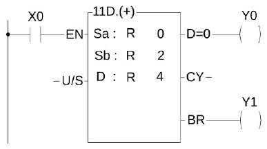
Function output diagram using FUN11
5-2 Use W Prefix for Word and Bit Access Transformation
The single-point (BIT state) memory of M-Series PLC can use W prefix word for word access, that is to access 16 single points at a time, for example, WX0 means one access to X0~X15 On the contrary, you can also use this technique to access any single-point state of the character group data, for example, you can place the character group data in WM0, if you want to read the 6th bit of the character group state, just read M6 directly.
5-3 Numbering System
5-3-1 Binary values and the terms
- Binary is the basic number system of digital computers. PLC is composed of digital computers, and naturally uses binary. In order to express and grasp binary values, you first need to understand the following terms:
- Bit: (Bit is abbreviated as B, such as B0, B1…) Bit is the most basic unit of binary value, and its state is either 1 or 0.
- Nibble: (Nibble is abbreviated as NB, such as NB0, NB1…) It is composed of 4 consecutive bits (such as B3~B0) and can be used to represent a decimal number 0~9 or 0~F in hexadecimal.
- Byte: (Byte abbreviated as BY, such as BY0, BY1…) is composed of two consecutive digits (that is, 8 bits, such as B7~B0). It can represent the two-digit value of hexadecimal 00~FF.
- Word group: (Word abbreviation W, such as W0, W1…) is composed of two consecutive bits (that is, 16 bits such as B15~B0) can represent 16 The 4-digit value in base system is 0000~FFFF.
- Double word group: (Double word abbreviation DW, such as DW0, DW1…) is composed of two consecutive word bytes (that is, 32 bits, such as B31~B0 ) can represent the 8-digit value of hexadecimal 00000000~FFFFFFFF.
|
DW |
←Double word group |
|||||||||||||||||||||||||||||||
|
W1 |
W0 |
←Word group |
||||||||||||||||||||||||||||||
|
BY3 |
BY2 |
BY1 |
BY0 |
←Byte |
||||||||||||||||||||||||||||
|
NB7 |
NB6 |
NB5 |
NB4 |
NB3 |
NB2 |
NB1 |
NB0 |
←Nibble |
||||||||||||||||||||||||
|
B31 |
B30 |
B29 |
B28 |
B27 |
B26 |
B25 |
B24 |
B23 |
B22 |
B21 |
B20 |
B19 |
B18 |
B17 |
B16 |
B15 |
B14 |
B13 |
B12 |
B11 |
B10 |
B9 |
B8 |
B7 |
B6 |
B5 |
B4 |
B3 |
B2 |
B1 |
B0 |
←Bit |
Schematic diagram of binary values and the terminology
Floating Point Number: It is composed of two consecutive word bytes. The maximum range that can be represented by floating point numbers is ±(1.8*10-38~3.4*1038), please refer to Section 5.3.6 for the detailed format description.
5-3-2 M PLC Digit
The numerical calculation or storage inside the M PLC all uses binary values (Binary), so the values input from the outside to the PLC must be converted into binary codes before the PLC can process them. Similarly, the numerical results retrieved from the PLC are also binary values so all the numbers of UpperLogic must be converted into binary before they can be input to PLC. However, because binary values are extremely difficult to input and read, UpperLogic provides users with the familiar decimal or hexadecimal to input or display in the man-machine interface (numerical input or display), But in fact, all numerical processing is carried out in binary code.。
Note: If your numerical input or display is not through UperLogic (for example, use a dip switch or a 7-segment display to input to or get from the PLC through the I/O point), then you have to use the ladder diagram program instructions to process the binary and the conversion between decimals allows you to input in decimals and get output in decimals without using UperLogic. Please refer to the description of FUN20(BIN→BCD) and FUN21(BCD→BIN).
5-3-3 Value Range
As mentioned above, all M PLCs use binary internally (the BCD value is only for people’s habit, and the binary value is converted into a digital display suitable for people to read). There are three types of values in PLC: 16-bit, 32-bit and floating-point numbers, which can represent the following ranges respectively.
|
16-bit |
-32768~32767 |
|
32-bit |
-2147483648~2147483647 |
|
Floating Point Number |
±(1.8*10-38~3.4*1038) |
5-3-4 Display of Values (Please skip this section for beginners)
The following sections describe the representation and format of 16-bit and 32-bit values. For users to have an in-depth understanding of the calculation process and results of numerical values and to meet various complex application requirements.
Whether it is a 16-bit or 32-bit value, its highest bit MSB (16-bit B15, 32-bit B31) indicates the sign of the value (0: positive number, 1: negative number), and the rest Bits (B14~B0 or B30~B0) are really used to represent the numerical value, hereby take 16 bits as an example to explain as follows: (32 bits are also done in the same way, only the length is doubled).
|
0:Positive Number |
16384 |
8192 |
4096 |
2048 |
1024 |
512 |
256 |
128 |
64 |
32 |
16 |
8 |
4 |
2 |
1 |
||||
|
12345 |
⇨ |
0 |
0 |
1 |
1 |
0 |
0 |
0 |
0 |
0 |
0 |
1 |
1 |
1 |
0 |
0 |
1 |
⇨ |
3039H |
|
(Decimal value) |
B15 |
B0 |
(Hex value) |
||||||||||||||||
8192+4096+32+16+8+1=12345
Schematic diagram of displayed values
As in the above example, regardless of 16-bit or 32-bit, the binary bits start from the lowest bit LSB (B0), B0 represents 1, B1 represents 2, B2 represents 4, B3 represents 8,…the rest can be deduced by analogy, and its value is the sum of the values represented by all the bits that are 1.
5-4 Use Index Register (XR) for Indirect Addressing
In the M-Series PLC function instructions, there are some operands that can be combined with pointer register (V, Z, P0~P9) to make indirect addressing (will be shown in the operand table if it applicable). Registers in the range RXXXXX can be combined with a pointer register to perform indirect addressing useing operand (V, Z), range RXXXXX can be combined with an pointer register to perform indirect addressing useing operand(P0~P9). Other operands such as discrete and constant cannot be used for indirect addressing).
There are twelve pointer registers XR (V, Z, P0~P9). The V register in the M PLC is R43214, and the Z register is R43216. The actual addressed register by index addressing is just offset the original operand with the content of the index register.
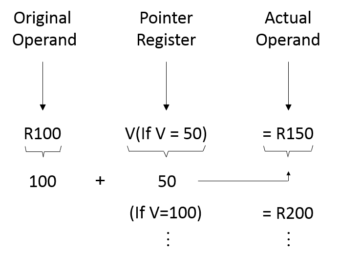
As shown in the above diagram, you only need to change the V value to change the operand address. After combining the index addressing with the M-Series PLC function instructions, a powerful and highly efficient control application can be achieved by using very simple instructions. Using the program shown in the diagram below as an example, you only need to use a block move instruction (BT_M) to achieve a dynamic block data display, such as a parking management system.
5-4-1 Index Register (P0~P9) Introduction
- In indirect addressing application, Rxxxxx register can combine V, Z , P0~P9 for index addressing; Dxxxxx register can’t combine V, Z for index addressing, but P0~P9 are allowed.
- When V, Z index register being combined with the Rxxxxx register, for example, R0 with V, Z, the instruction format is R0V (where V=100, it means R100) or R0Z(where Z=500, it means R500); when P0~P9 index register being combined with the Rxxxxx register, the instruction format is RPn (n=0~9) or RPmPn (m,n=0~9), for example RP5 (where P5=100, it means R100) or RP0P1(where P0= 100, P1=50, it means150).
- When P0~P9 index register being combined with the Dxxxxx register, the instruction format is DPn (n=0~9) or DPmPn (m, n=0~9), for example DP3 (where P3=10, it means D10) or DP4P5 (where P4=100, P5=1, it means D101).
- It can combine both P0~P9 index register, for example P2=20, P3=30, when Rxxxxx or Dxxxxx register combines both index register, RP2P3 will point to R50, DP2P3 will point to D50, it means the summation of both indexes register for indirect addressing.
|
|
Coping the content of R100~R103 for R2000~R2003 at first execution, coping the content of R104~R107 for R2000~R2003 at second execution…
|
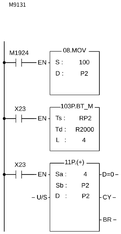
5-4-2 Indirect Addressing Program Example
|
Ladder Diagram |
|
|
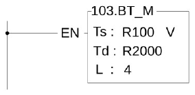
Ladder Diagram of FUN103 BT_M
|
resident |
Pointer Register V |
|
||||||||||
|
R100 |
Name |
4 |
Sensor Station |
|||||||||
|
(V=0) Resident1 |
R101 |
Tel. No. |
||||||||||
|
R102 |
Car plate No. |
|||||||||||
|
˙ ˙ ˙ |
R103 |
Parking No. |
||||||||||
|
R104 |
Name |
|||||||||||
|
(V=4) Resident2 |
R105 |
Tel. No. |
||||||||||
|
R106 |
Car plate No. |
|||||||||||
|
˙ ˙ ˙ ˙ ˙ ˙ ˙ ˙ ˙ |
R107 |
Parking No. |
||||||||||
|
˙ ˙ ˙ ˙ ˙ ˙ |
⭘ |
Monitor |
||||||||||
|
Temporary Display Storage Area |
XX Community Resident Parking System |
|||||||||||
|
R2000 |
Name |
|||||||||||
|
R2001 |
Tel. No. |
Name |
(R2000) |
|||||||||
|
(V=396) |
Name |
R2002 |
Car plate No. |
Tel. No |
(R2001) |
|||||||
|
Resident100 |
Tel. No. |
R2003 |
Parking No. |
Car No. |
(R2002) |
|||||||
|
Car plate No. |
Parking No. |
(R2003) |
||||||||||
|
Rnnn |
Parking No. |
|||||||||||
 Resident 2
Automated Parkinglot Management System
Program Description
The above example assumes that the automated parking lot management system for residents in a community has a total of 100 resident parking spaces, and each resident has 1 set of basic information, which are resident name, phone number, car plate number, parking number, etc. As shown in the figure above, it occupies 4 consecutive PLC internal temporary registers, occupying a total of 400 temporary registers such as R100~R499. Each household has a card with a different card number, which is used for entrance and exit control and parking lot. 0, 4, ∙∙∙∙∙∙, 396, etc. 100 types, after the PLC senses the card number, it will be stored in the index temporary register "V", and displayed on the terminal (LCD or CRT) at the administrator’s office The data is captured and displayed by R2001~R2003 inside the PLC. For example, in this example, the card of resident 2 is sensed, and its value=4, so the V register=4, and the PLC immediately moves the data of R104~R107 to the display Temporary storage area (R2000~R2003), so the terminal at the administrator can immediately display the information on the terminal when it senses the card of resident 2.
|
! Warning |
|
5-4-3 Representation of Negative Number (Beginners should skip this section)
As prior discussion, when the MSB is 1, the number will be a negative number. The M-Series PLC negative numbers are represented by 2’S Complement, i.e to invert all the bits (B15~B0 or B31~B0) of its equivalent positive number (The so-called 1’S Complement is to change the bits equal 1 to 0 and the bits equal 0 to 1) then add 1. In the above example, the positive number is 12345. The calculation of its 2’S Complement (i.e. –12345) is described below:
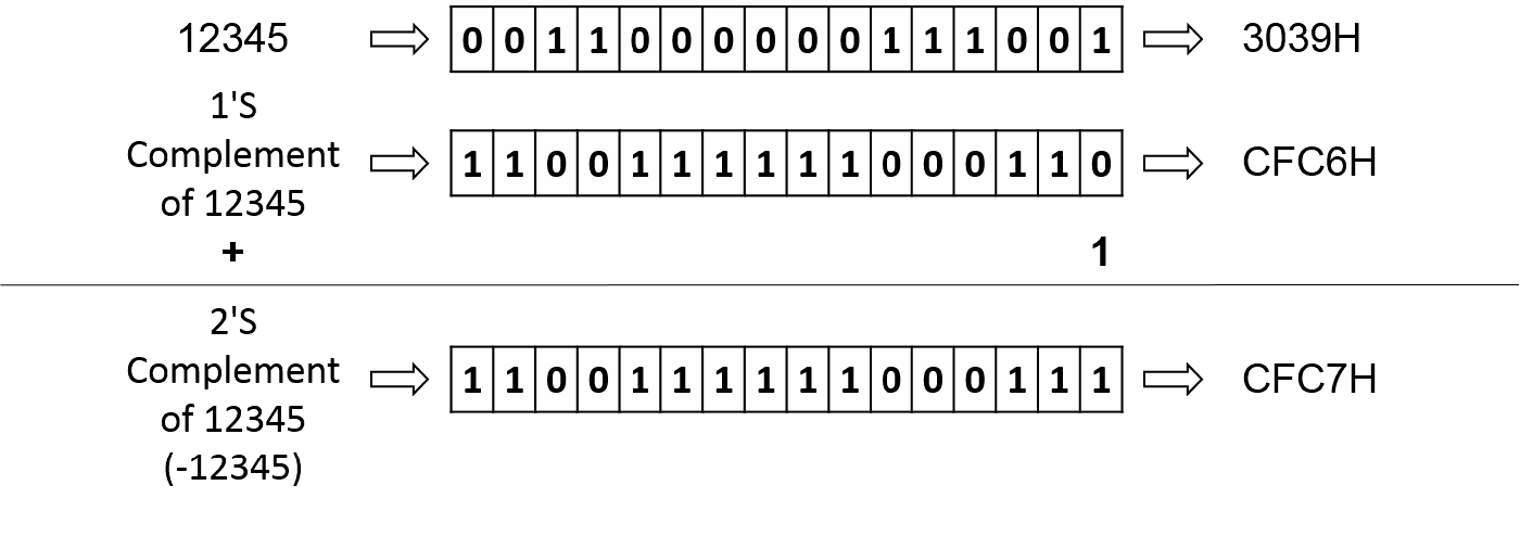
Example of Negative Number
5-4-4 Representation of Floating Point Number (Beginners should skip this section)
The format of floating point number of FATEK-PLC follows the IEEE-754 standard, which use a double word for storage and can be expressed as follow :
floating point number = sign + Exponent + Mantissa
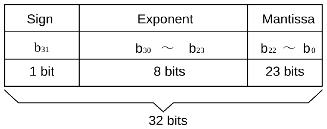
Representation of Floating Point Number
If the sign bit is 0 the number is positive, if the sign bit is 1 the number is negative.
The exponent is denoted as 8-bit excess 127. For example, if the value of exponent is 128, it represents the power of 1, if the value of exponent is 129, it represents the power of 2 . . . So on and so forth.If you want to express the negative value of the exponent, then 126 is the power of -1, and 125 is the power of -2. . . So on and so forth.
The mantissa is 23-bit with radix 2. A normalized mantissa always starts with a bit 1, followed by the radix point, followed by the rest of the mantissa. The leading bit 1, which is always present in a normalized mantissa, is implicit and is not represented.
N = ( -1) S * 2 (E -127) * (1.M) 0 < E < 255
Example 1
1 = ( -1 ) 0 * 2 ( 01111111 ) * ( 1.000....... 0)
The sign is represented by 0, the exponent’s code in excess 127 is 127 = 01111111, and the significant bit is 1, resulting in the mantissa being all O’s. The simple precision IEEE 754 representation of 1, is thus:
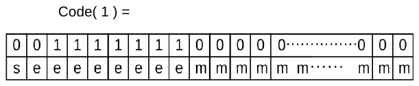
= 3F800000H
Example 2
0.5 = ( -1 ) 0 * 2 ( 01111110 ) * (1.000....... 0)
The sign is represented by 0, the exponent’s code in excess 127 is 126 – 127 = 01111110, and the significant bit is 1, resulting in the mantissa being all O’s. The simple precision IEEE 754 representation of 0.5, is thus:
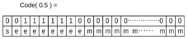
= 3F000000H
Example 3
-500.125 = ( -1) 1 * 2 ( 10000111 ) * ( 1. 11110100001000000000000)
The sign is represented by 1, the exponent’s code in excess 127 is 135 – 127 = 10000111, and the significant bit is 1, resulting in the mantissa is 11110100001000000000000. The simple precision IEEE 754 representation of -500.125, is thus:

= C3FA1000H
5-5 Overflow and Underflow of Increment (+1) or Decreme nt (-1) Instruction (Beginners please skip this section
The maximum positive value that can be represented by 16-bit and 32-bit operands are 32767 and 2147483647, and the maximum negative value are -32768 and -2147483648, respectively. When increase or decrease an operand (e.g., when Up/Down Count of a counter or the register value is +1 or -1), and the result exceeds the value of the positive limit of the operand, then “Overflow” (OVF) occurs. This will cause the value to cycle to its negative limit (e.g., add 1 to the 16-bit positive limit 32767 will change it to –32768). If the result is smaller than the negative limit of the operand, then “Underflow” (UDF) occurs. This will cause the value to cycle to its positive limit (e.g., deducting 1 from the negative limit –32768 will change it to 32767) as shown in the table below. The flag output of overflow or underflow exists in the FO of M-Series PLC and can be used in cascaded instructions to obtain over 16-bit or 32-bit operation results.
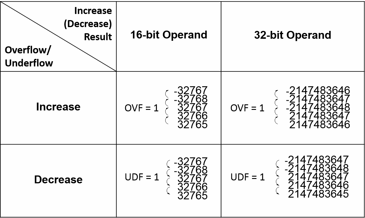
Increment or Decrement in 16-bit and 32-bit Operand
5-6 Carry and Borrow in Addition/Subtraction
Overflow/Underflow takes place when the operation of increment/decrement causes the value of the operand to exceed the positive/negative limit that can be represented in the PLC, consequently a flag of overflow/underflow is introduced. Carry/Borrow flag is different from overflow/underflow. At first, there must be two operands making addition (subtraction) where a sum (difference) and a flag of carry/borrow will be obtained. Since the number of bits of the numbers to be added (subtracted), to add (subtract) and of sum (difference) are the same (either 16-bit or 32-bit), the result of addition (subtraction) may cause the value of sum (difference) to exceed 16-bit or 32-bit. Therefore, it is necessary to use carry/borrow flag to be in coordination with the sum (difference) operand to represent the actual value. The carry flag is set when the addition (subtraction) result exceeds the positive limit (32767 or 2147483647) of the sum (difference) operand. The borrow flag is set when addition (subtraction) result exceeds the negative limit (-32768 or -2147483648) of the sum (difference) operand. Hence, the actual result after addition (subtraction) is equal to the carry/borrow plus the value of the sum (difference) operand. The FO of M-Series PLC addition/subtraction instruction has both carry and borrow flag outputs for obtaining the actual result.
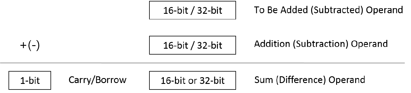
16-bit and 32-bit Addition/Subtraction
While all M-Series PLC numerical operations use 2’S Complement, the representation of the negative value of the sum (difference) obtained from addition (subtraction) is different from the usual negative number representation. When the operation result is a negative value, 0 can never appear in the MSB of the sum (difference) operand. The carry flag represents the positive value 32768 (2147483648) and the borrow flag represents the negative value -32768 (-2147483648).
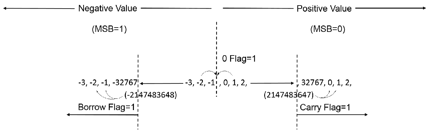
|
∙ ∙ |
MSB ↓ |
∙ ∙ |
LSB ↓ |
∙ ∙ |
|
|||||||||||||
|
C=1 B=0 Z=0 |
0 |
0 |
0 |
0 |
0 |
0 |
0 |
0 |
0 |
0 |
0 |
0 |
0 |
0 |
0 |
1 |
32769 |
|
|
C=1 B=0 Z=0 |
0 |
0 |
0 |
0 |
0 |
0 |
0 |
0 |
0 |
0 |
0 |
0 |
0 |
0 |
0 |
0 |
32768 |
|
|
C=0 B=0 Z=0 |
0 |
1 |
1 |
1 |
1 |
1 |
1 |
1 |
1 |
1 |
1 |
1 |
1 |
1 |
1 |
1 |
32767 |
|
|
C=0 B=0 Z=0 |
0 |
1 |
1 |
1 |
1 |
1 |
1 |
1 |
1 |
1 |
1 |
1 |
1 |
1 |
1 |
0 |
32766 |
|
|
C=0 B=0 Z=0 |
0 |
1 |
1 |
1 |
1 |
1 |
1 |
1 |
1 |
1 |
1 |
1 |
1 |
1 |
0 |
1 |
32765 |
|
|
∙ ∙ ∙ ∙ ∙ |
∙ ∙ ∙ ∙ ∙ |
|||||||||||||||||
|
C=0 B=0 Z=0 |
0 |
0 |
0 |
0 |
0 |
0 |
0 |
0 |
0 |
0 |
0 |
0 |
0 |
0 |
1 |
0 |
2 |
|
|
C=0 B=0 Z=0 |
0 |
0 |
0 |
0 |
0 |
0 |
0 |
0 |
0 |
0 |
0 |
0 |
0 |
0 |
0 |
1 |
1 |
|
|
C=0 B=0 Z=1 |
0 |
0 |
0 |
0 |
0 |
0 |
0 |
0 |
0 |
0 |
0 |
0 |
0 |
0 |
0 |
0 |
0 |
|
|
C=0 B=0 Z=0 |
1 |
1 |
1 |
1 |
1 |
1 |
1 |
1 |
1 |
1 |
1 |
1 |
1 |
1 |
1 |
1 |
-1 |
|
|
C=0 B=0 Z=0 |
1 |
1 |
1 |
1 |
1 |
1 |
1 |
1 |
1 |
1 |
1 |
1 |
1 |
1 |
1 |
0 |
-2 |
|
|
∙ ∙ ∙ ∙ ∙ |
∙ ∙ ∙ ∙ ∙ |
|||||||||||||||||
|
C=0 B=0 Z=0 |
1 |
0 |
0 |
0 |
0 |
0 |
0 |
0 |
0 |
0 |
0 |
0 |
0 |
0 |
1 |
0 |
-32766 |
|
|
C=0 B=0 Z=0 |
1 |
0 |
0 |
0 |
0 |
0 |
0 |
0 |
0 |
0 |
0 |
0 |
0 |
0 |
0 |
1 |
-32767 |
|
|
C=0 B=0 Z=0 |
1 |
0 |
0 |
0 |
0 |
0 |
0 |
0 |
0 |
0 |
0 |
0 |
0 |
0 |
0 |
0 |
-32768 |
|
|
C=0 B=1 Z=0 |
1 |
1 |
1 |
1 |
1 |
1 |
1 |
1 |
1 |
1 |
1 |
1 |
1 |
1 |
1 |
1 |
32769 |
|
|
C=0 B=1 Z=0 |
1 |
1 |
1 |
1 |
1 |
1 |
1 |
1 |
1 |
1 |
1 |
1 |
1 |
1 |
1 |
0 |
-32770 |
|
|
∙ ∙ |
∙ ∙ |
∙ ∙ |
||||||||||||||||
|
C = Carry B = Borrow Z = Zero |
||||||||||||||||||

Carry and Borrow in Addition/Subtraction
※If carry and borrow processing is not required, it is recommended to use Fun224 fast addition and Fun225 fast subtraction, because compared with Fun11 addition and Fun12 subtraction, no carry/borrow is required
Tip: press ← → to switch chapters, Ctrl+K to search