This chapter only describes the Element features and functions of sequence commands.
4-1 Element Description
4-1-1 Characteristics of A,B,TU and TD Contacts
|
Characteristics of A,B,TU and TD Contacts |
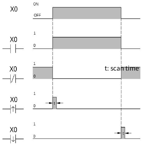
The waveform shown above reveals the function of A, B, TU and TD elements by exercising the external input X0 form OFF to ON then OFF.
- TU (Transition Up): This is the “Transition Up Contact”. Only a rising edge (0🡪1) of the referenced signal will turn on this element for one scan time.
- TD (Transition Down): This is the “Transition Down Contact”. Only a falling edge (1🡪0) of the referenced signal will turn on this element for one scan time.
- TU and TD contact will automatically generate the TU or TD pulse corresponding to the contacts or coils for all X, Y, M, S, T, C contact or coil state changes. However, if the state change of the coil is operated by the "application Instruction" in units of 16 or 32 bits(WY△△△△,WM△△△△△,WS△△△△), TU or TD pulses will not be generated.
Note: The "ON" maintenance time of the TU and TD elements of the M PLC relay is the first scan after the "ON" condition of the element is established (for example, the TU element changes from 0 to 1, and the TD element changes from 1 to 0). Set it to "ON" for coil elements. Once it is set to "ON", it will be cleared to "OFF" immediately when it is scanned again. In most applications, each element will only be scanned once during the CPU problem-solving scan cycle, so the "ON" time of TU and TD elements must be equal to the scan time of the CPU. However, if it is scanned more than once in a CPU scan cycle (such as using "immediate input" or "multiple coil output" in the program), the TU and TD states of its elements will be the first time the "ON" condition is met. Set to "ON" when the scan arrives, and clear to "OFF" immediately when the second scan arrives, and the "ON" time will be less than one CPU scan time. The TU of Y0 in the following illustration is that. Therefore, if the customer needs to capture the TU of Y0 for trigger operation, one must insert the application program in the range of Y0 TU "ON" to "OFF" (in this example, between b and e), otherwise he will not be able to capture any Y0 or TU trigger signal.
|
Ladder Diagram |
|
|
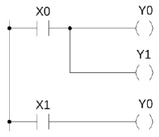
Example diagram of the contact and scan time relationship
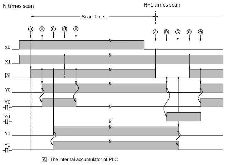
PLC contact trigger and scan time relationship
- Besides the TU/TD instructions which can detect the status change of reference operand, M PLC also provides the instructions to detect the change of node
status (power flow). For details please refer the descriptions of FUN4 (DIFU) and FUN5 (DIFD) instructions.
4-1-2 OPEN and SHORT Contact
The status of OPEN and SHORT contacts are fixed and can’t be changed by any ladder instructions. Those two contacts are mainly used in the places of the Ladder Diagram where fixed contact statuses are required, such as the place where the input of an application instruction is used to select the mode. The sample program shown below gives an example of configuring an Up/Down counter (UDCTR) to an Up counter by using the SHORT contact.
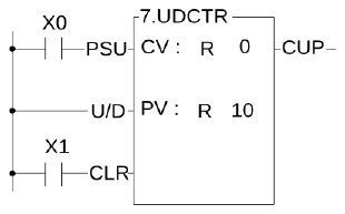
Up counter using the SHORT contact
- FUN7 is the UDCTR function. While rising edge of CK input occur, FUN7 will count up if the U/D status is 1 or count down if the U/D status is 0. The example shown above, U/D status is fixed at 1 since U/D is directly connected from the origin-line to a SHORT contact, therefore FUN7 becomes an Up counter. On the contrary, if the U/D input of FUN7 is connected with an OPEN contact from the origin-line, the FUN7 becomes a DOWN counter.
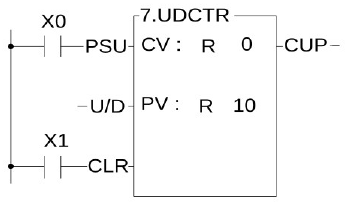
Down counter using the OPEN contact
4-1-3 Output Coil and Inverse Output Coil
Output Coil writes the node status into an operand specified by the coil instruction. Invert Output Coil writes the complement status of node status into an operand specified by the coil instruction. The characteristics depicts at below.
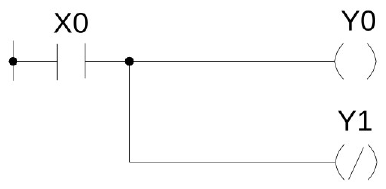
Ladder Diagram of Output Coil and Invert Output Coil
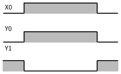
Output Coil and Invert Output Coil
4-1-4 Retentive Output Coil
For the internal coil, it can be set as holding or non-holding (it is a dichotomy, such as M0-M8519 of the internal coil M0-M9119 is non-holding, then M8520-M9119 is holding), but for the output point, due to practical It is not suitable to use the dichotomy method to set hold or non-hold, so if most PLCs need to hold the output point, they must first send the result to the internal hold coil, and then send the internal hold coil to the indirect method of the output point, M PLC Then provide you with the method of selecting the output point to be maintained under the page of I/O Configuration -> Output Power Failure Hold, the following self-protection circuit:
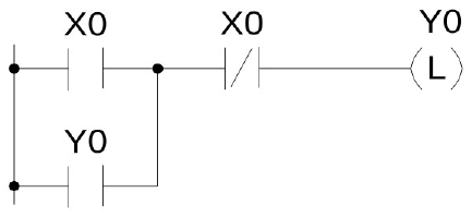
Ladder Diagram of Retentive Output Coil
From the above example, if turn the X0 "ON" then "OFF", Y0 will keep at "ON". When change the PLC state from RUN to STOP then RUN or turn the power off then on, the Y0 still keep at ON state. But if use the OUT Y0 instruction instead of the OUT L Y0, need to turn the X0 "ON" again after change the PLC state from RUN to STOP then RUN or turn the power off then on, Y0 status will be ON.
4-1-5 Set Coil and Reset Coil
Set Coil writes 1 into an operand specified. Reset Coil writes 0 into an operand specified. The characteristics depicts at below.
.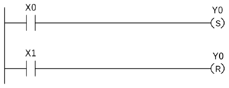
Ladder Diagram of Set Coil and Reset Coil
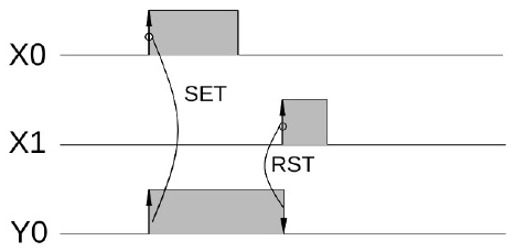
Set Coil and Reset Coil
Tip: press ← → to switch chapters, Ctrl+K to search