Structured programming design is a major trend in software design. The benefits are high readability, easy maintenance, convenient updating and high quality and reliability. For the control applications, consisted of many sequential tasks, designed by conventional ladder program design methodology usually makes others hard to maintain. Therefore, it is necessary to combine the current widely used ladder diagrams with the sequential controls made especially for machine working flow. With help from step instructions, the design work will become more efficient, time saving and controlled. This kind of design method that combines process control and ladder diagram together is called the step ladder language.
The basic unit of step ladder diagram is a step. A step is equivalent to a movement (step) in the machine operation where each movement has an output. The complete machine or the overall sequential control process is the combination of steps in serial or parallel. Its step-by-step sequential execution procedure allows others to be able to understand the machine operations thoroughly, so that design, operation, and maintenance will become more effective and simpler.
8-1 The Operation Principle of Step Ladder Diagram
|
【Example】 |
【Description】 |
|
|
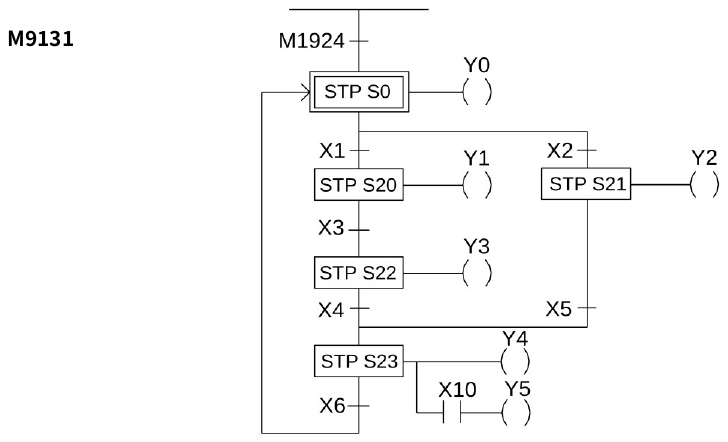
X2 ON⇒ ⇒ Y2 will remain ON until X5 is ON.
i.e. X5 ON⇒ ⇒ Y4 and Y5 will remain ON until X6 is ON. ※If X10 is ON, then Y5 will be ON.。
i.e. X6 ON⇒ ⇒ Then, a control process cycle is completed and the next control process cycle is entered. |
8-2 Basic Formation of Step Ladder Diagram
|
➀Single path |
|
|
|
|
|
➁Selective divergence/convergence |
|
|
|
|
|
➂Simultaneous divergence/convergence |
|
|
|
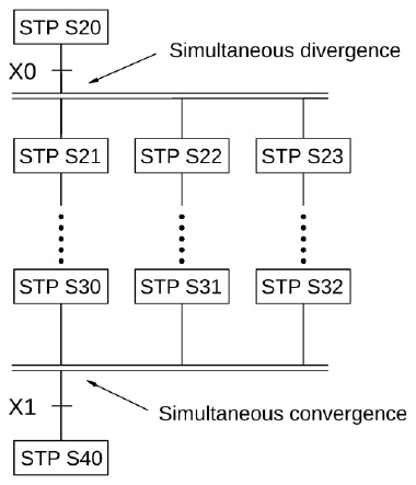
After X0 is ON, step S20 will simultaneously execute all paths below it, i.e. all S21, S22, S23, and so on, are in action.
|
|
➃Jump |
|
|
a. The same step loop |
|
|
|
|
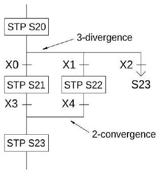
|
b. Different step loop |
|
|
|
|
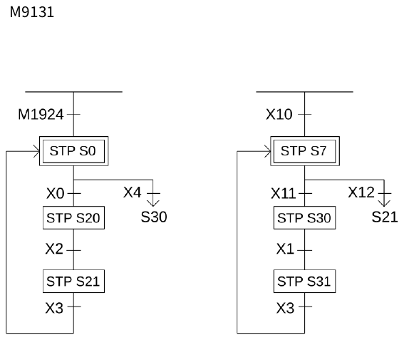
|
➄Close Loop and Single Cycle |
|
|
a. Close Loop |
|
|
|
|
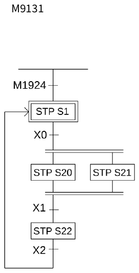
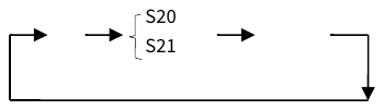 S1 S22
|
b. Single Cycle |
|
|
|
|
|
c. Mixed Process |
|
|
|
|
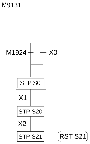
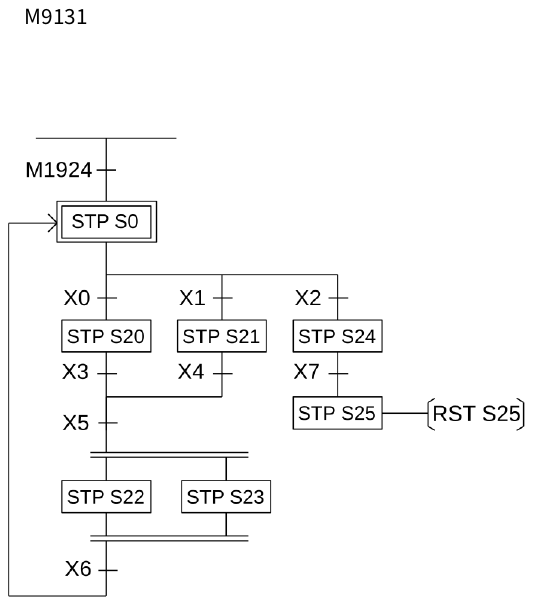
|
➅Combined Application |
|
|
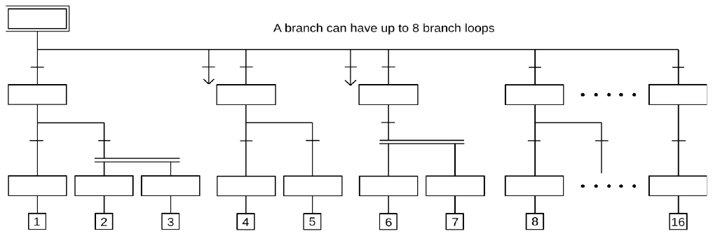
The maximum number of downward horizontal branch loops of an initial step is 16 |
|
8-3 Introduction of Step Instruction:STP、FROM、TO、STPEND
This section will introduce step instructions, and how to call instructions in UpperLogic, and how to use them.
Step instructions can be called by:
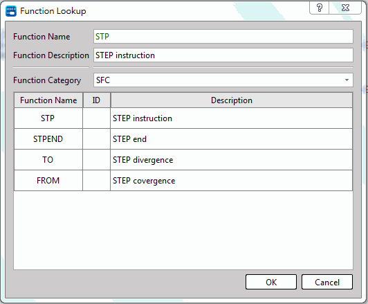
Select the function bar Ladder → Function Instruction;Or click the component panel icon; or right-click in the ladder diagram program area to display a pop-up menu, Function Instruction → Function Instruction, click on the position where you want to input the step command in the ladder diagram program area, All categories of function instructions will appear, select[SFC instruction], there are four step instructions [STP], [FROM], [TO], and [STPEND] on the right of the instruction name, as shown in the figure below::
8-3-1 STP
- STP Sx :S0 ≦ Sx ≦ S7(Displayed in UperLogic)or STP Sx:S0 ≦ Sx ≦ S7
This instruction is the initial step instruction, from which the step control of each mechanical process can be derived. M-Series can provide up to 8 initial step points, that is to say, a PLC can control up to 8 processes at the same time. each step process can operate independently or generate operation results for reference by other processes.
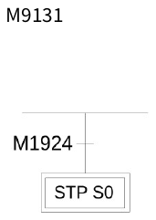
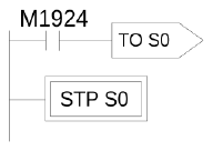
【Example 1】Start the initial step point S0 every time when turn on PLC
|
|
UperLogic |
||
|
|
|
||

【Example 2】Every time turn on PLC or press the button, or an abnormality in automatic production occurs and there is no personnel to deal with it within a certain period of time, it will automatically enter the initial step point S0 and stand by.
|
UperLogic |
|||
|
|
|
||
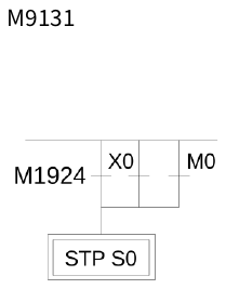
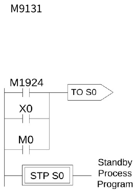
【Description】X0:button;M0:Abnormal Contact
- STP Sxxxx :S20≦Sxxxx≦S3103(Displayed in UperLogic)
or
STP Sxxxx : S20≦Sxxxx≦S3103
This instruction is a step instruction, each step in a process represents a step of sequence. If the status of step is ON then the step is active and will execute the ladder program associate to the step.
【Example】
|
|
|||
|
|
|
||
 UperLogic
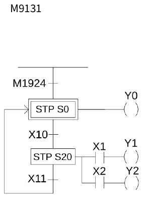
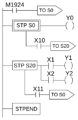
【Description】
1. When ON, the initial step S0 is ON and Y0 is ON.
2. When transfer condition X10 is ON (in actual application, the transferring condition may be formed by the serial or parallel combination of the contacts X, Y, M, T and C), the step S20 is activated. The system will automatically turn S0 OFF in the current scan cycle and Y0 will be reset automatically to OFF.
|
S20 ON S0 OFF |
⇒ |
X1 ON X2 ON Y0 OFF |
🡪Y1 ON 🡪Y2 ON |
||
|
i.e.X10 ON⇒ |
|||||
3. When the transfer condition X11 is ON, the step S0 is ON, Y0 is ON and S20, Y1 and Y2 will turn OFF at the same time.
|
S0 ON S20 OFF |
⇒ |
Y0 ON Y1 OFF Y2 OFF |
||
|
i.e.X11 ON⇒ |
||||
- Enter step point (STP Insruction)
If we want to set an initial step point S0 for each boot, the method is as follows:
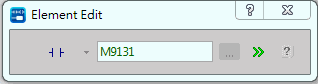
Select the A contact component on the component tray, click on the ladder diagram network, and enter "M9131" in the number input box :
Click on the component panel icon, click after the "M9131" contact, the [Application Command] window will appear, select "SFC Instruction" under [Type], select "TO" for [Instruction Name], and press the "OK" button , the following window appears :
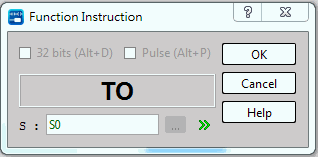
Enter "S0", press the "OK" button, and repeat the "SF instruction", this time select "STP" for [instruction name], and the following figure will appear :
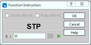
Input "S0" and press the "OK" button to complete the operation of setting an initial step point S0 for each boot.

You can also add state transition conditions for the initial step point. First, place the cursor on the component panel to select the [vertical line] component, and then click on "STPI S0"; or stop the cursor on "STPI S0", and then press the shortcut key "V" works too.

After the divergence line appears, add transition conditions, for example, we add two transition conditions "X0" and "Y0".
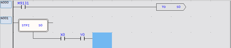
After adding the state point to be transferred, we assume that when the two transfer conditions of "X0" and "Y0" are satisfied (ON), it will transfer to the state point "S21". Call out the [SFC function instruction] category, select [TO] for the instruction name; or press the shortcut key “>”, after a dialog box appears, enter “S21” to complete the following example :

8-3-2 FROM
- FROM Sxxxx :S0 ≦ Sxxxx ≦ S3103(Displayed in UperLogic)
The instruction describes the source step of the transfer, i.e. moving from step Sxxxx to the next step in coordination with transfer condition.
【Example】
|
|
|||
|
|
|
||
 UperLogic
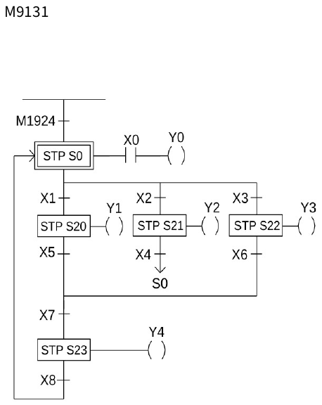
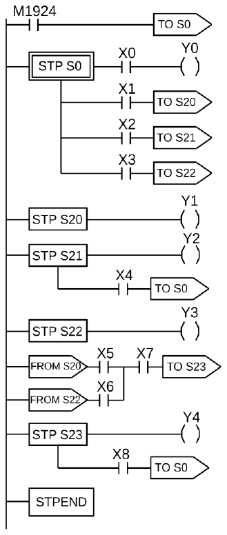
【Description】:
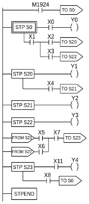
1. When ON, the initial step S0 is ON. If X0 is ON, then Y0 will be ON.
2. When S0 is ON: a. if X1 is ON, then step S20 will be ON and Y1 will be ON.
b. if X2 is ON, then step S21 will be ON and Y2 will be ON.
c. if X3 is ON, then step S22 will be ON and Y3 will be ON.
d. if X1, X2 and X3 are all ON simultaneous, then step S20 will have the priority to be ON first and either S21 or S22 will not be ON.
e. if X2 and X3 are ON at the same time, then step S21 will have the priority to be ON first and S22 will not be ON.。
3. When S20 is ON, if X5 and X7 are ON at the same time, then step S23 will be ON, Y4 will be ON and S20 and Y1 will be OFF.
4. When S21 is ON, if X4 is ON, then step S0 will be ON and S21 and Y2 will be OFF.
5. When S22 is ON, if X6 and X7 are ON at the same time, then step S23 will be ON, Y4 will be ON and S22 and Y3 will be OFF.
6. When S23 is ON, if X8 is ON, then step S0 will be ON and S23 and Y4 will be OFF.
- Enter convergence point (FROM)
- selective convergence

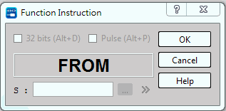
If we want to make the above results, we will do the following: We first call the [SFC function instruction] category by referring to the operation method in section 7.4.2, select [FROM] for the instruction name, and press“OK”, and the following window will appear.
Input "S21", press the "OK" button, move the cursor on the component panel to select the [A contact] component and click it, the following window will appear:

Input "X5", press "ENTER", use the function instruction again, call out the [SFC function instruction] category, select [FROM] for the instruction name, and press "OK".
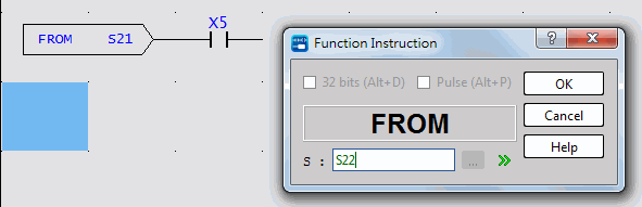
Input "S22", press the "OK" button, move the cursor on the component panel to select the [A contact] component and click it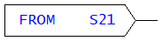 , the following window will appear :
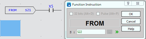
Input "X6", press "ENTER" , the cursor will select the [vertical line] component in the component panel, click it immediately after the X5 contact; or press the shortcut key "V" after the cursor is placed in X5, a vertical line will appear. line, as shown in the following figure :
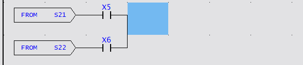
Enter "X7", as shown in the following image:
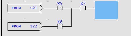
Use the function command again, call out the [SFC function instruction] category, select [TO] for the instruction name, and then press "OK" to appear.
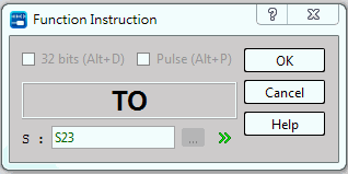
Input "S23" and press "OK" to complete an example of selective convergence. As shown below.

- Simultaneous convergence

If we want to make the above result, the method is as follows: We first call the [SFC function instruction] category by referring to the operation method in section 7.4.2, select [FROM] for the instruction name, and press “OK”, and the following window will appear:
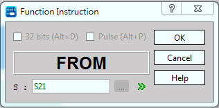
Input "S21", press "OK", call out the [SFC function instruction] category again, select [FROM] for the instruction name, and press "OK", the following window will appear :
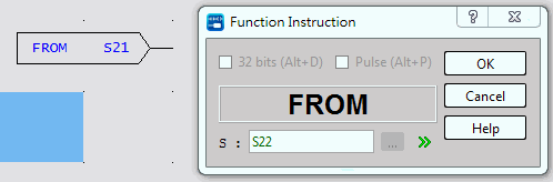
Enter "S22", press "OK" , select the [vertical line] component with the cursor on the component panel, and then click it; or press the shortcut key "V", that is, to complete the expression of the parallel and confluent ladder diagram program.
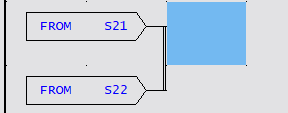
Select the [A Contact] component with the cursor on the component panel, and then click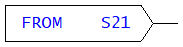 :
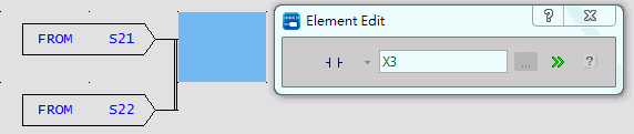
Enter "X3" and press "ENTER". Use the function command again, call out the [SFC function instruction] category, select [TO] for the instruction name and press "OK", and the following window will appear:
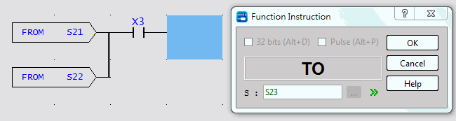
Input "S23" and press "OK" to complete the example of simultaneous convergence. As shown below:

Special attention should be paid to the [vertical line] element in order to complete the simultaneous convergence. It must be next to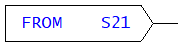 . Once there is a space in the middle, it will become a selective convergence, as shown below:

8-3-3 TO
- TO Sxxxx :S0≦Sxxxx≦S3103(Displayed in UperLogic)
This instruction describes the step to be transferred to.
【Example】
|
|
|||
|
|
|
||
 UperLogic
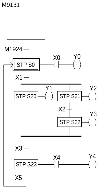
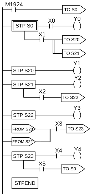
【Description】:
- When ON, the initial step S0 is ON. If X0 is ON, then Y0 will be ON.
- When S0 is ON: if X1 is ON, then steps S20 and S21 will be ON simultaneously and Y1 and Y2 will also be ON.
- When S21 is ON: if X2 is ON, then step S22 will be ON, Y3 will be ON and S21 and Y2 will be OFF.
- When S20 and S22 are ON at the same time and the transferring condition X3 is ON, then step S23 will be ON (if X4 is ON, then Y4 will be ON) and S20 and S22 will automatically turn OFF and Y1 and Y3 will also turn OFF.
- When S23 is ON: if X5 is ON, then the process will transfer back to the initial step, i.e. So will be ON and S23 and Y4 will be OFF.
- Enter divergence point (TO Instruction)
Using the UperLogic ladder diagram program are as follows:
- Selective Divergence

If we wanted to make the above result :
Place the cursor at the desired input position in the program area, call out the [SFC function instruction] category, and select the instruction name [FROM] :
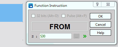
Input "S30" and press "OK", the FROM instruction S30 element will appear in the program area. Cursor to select the A contact element and click on it, and enter the "X3" number; or directly enter "AX3" directly after it, as shown in the following window:

Type X0 followed by it,

Place the cursor at the desired input position in the program area, then call the [SFC function instruction] category, and select [TO] ;
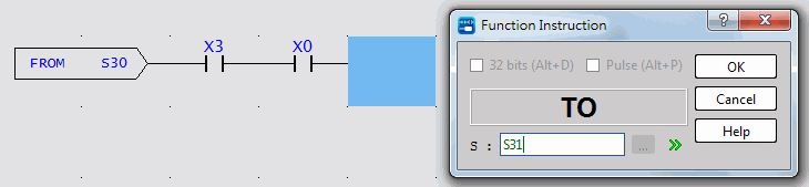
Enter "S31", press "OK", the cursor is placed at the X0 position, enter "V", and add a vertical line, as shown in the following figure:

Place the cursor below X0 and enter "X1" or "X1A":

Call the [SFC function instruction] category, and select [TO]:
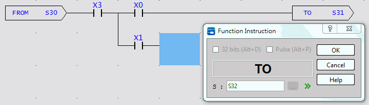
Input "S32" and press "OK", an example of selective divergence is completed. As shown below:

- Simultaneous Divergence

If we want to make the above result, the method is as follows :
Place the cursor at the desired input position in the program area, call the [SFC function instruction] category, and select [FROM]:
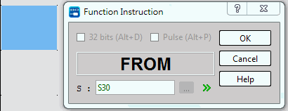
Input "S30" and press "OK", the FROM instruction will appear. Cursor to select the A-contact component, click and select it, and enter "X3" or "AX3", as shown in the following window:

Place the cursor at the desired input position in the program area, call the [SFC function instruction] category, and select [TO]:
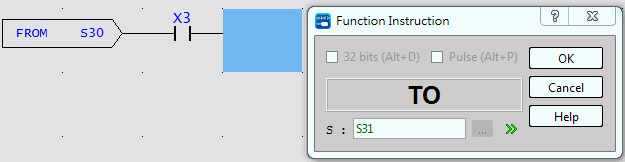
Input "S31" and press "OK", the TO instruction will appear. At the position below the instruction TO command S31, call the [SFC function instruction] category, and select [TO]:
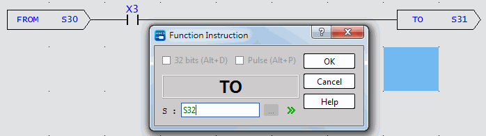
Enter "S32" and press "OK". Select the vertical line component, click the icon in the program area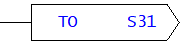 ; or press the shortcut key "V", the following figure will appear:

That is, to complete the example of Simultaneous divergence.
8-3-4 STPEND
- STPEND :(Displayed in UperLogic)
This instruction represents the end of a process, which is required for all processes to work correctly.
PLC has at most 8 step processes (S0~S7) that can be controlled at the same time, so there are at most 8 STPEND instructions.
【Example】
|
|
|||
|
|
|
||
 UperLogic
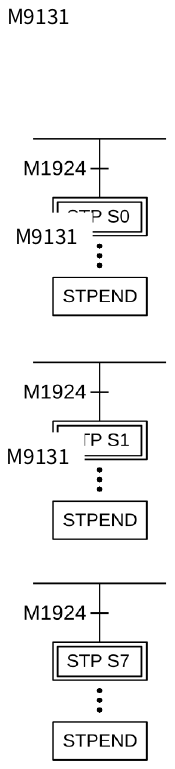
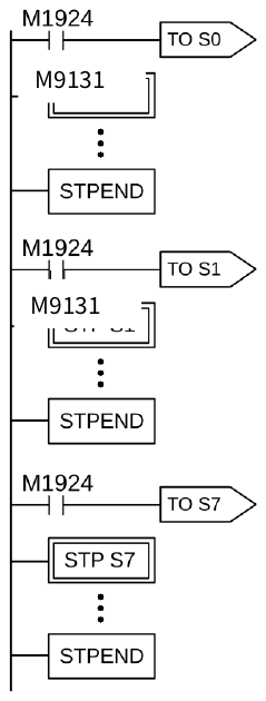
【Description】8 step processes are activated at the same time when PLC boot.
‘’
8-4 Notes for Writing a Step Ladder Diagram
【Notes】
- In actual applications, the ladder diagram can be used together with the step ladder.
- There are 8 steps, S0~S7, that can be used as the starting point and are called the “initial steps”.
- When PLC starts operating, it is necessary to activate the initial step. The M9131 (the first scan ON signal) provided by the system may be used to activate the initial step.
- Except the initial step, the start of any other steps must be driven by other step.
- It is necessary to have an initial step and the final STPEND instruction in a step ladder diagram to complete a step process program.
- There are 3085 steps, S20~S3103, available that can be used freely. However, used numbers cannot be repeated. S2064~S3103 are retentive(The range can be modified by users), can be used if it is required to continue the machine process after power is off.
- Basically, a step must consist of three parts which are control output, transition conditions and transition targets.
- MC and SKP instructions cannot be used in a step program and the sub-programs. It’s recommended that JMP instruction should be avoided as much as possible.
- If the output point is required to stay ON after the step is divergent to other step, it is necessary to use the SET instruction to control the output point and use RST instruction to clear the output point to OFF.
- Looking down from an initial step, the maximum number of horizontal paths is 16. However, a step is only allowed to have up to 8 branch paths.
【Example 1】
|
|
|
|
|
|
 UpreLogic
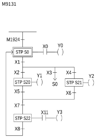
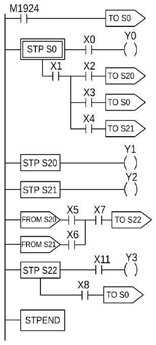
【Description】:1. Input the condition to initial step S0
2. Input the S0 and the divergent conditions of S20, S0 and S21
3. Input the S20
4. Input the S21
5. Input the convergence of S20 and S21
6. Input the S22
【Example 2】
|
|
|||
|
|
⇒ |
|
⇒ |
 UperLogic
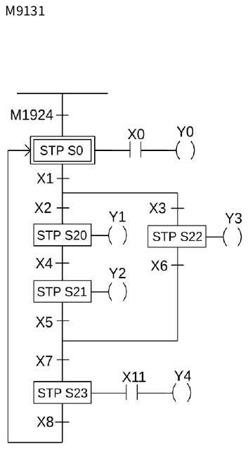
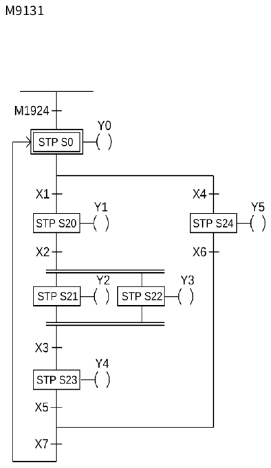
【Description】:1. Input the condition to initial step S0
2. Input the S0 and the divergent condition of S20 and S22
3. Input the S20
4. Input the S21
5. Input the S22
6. Input the convergence of S21 and S22
7. Input the S23【Example 3】
|
UperLogic |
|||
|
|
⇒ |
|
⇒ |
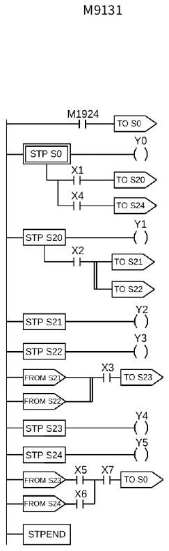
【Description】:1. Input the condition to initial step S0
2. Input the S0 and the divergences of S20 and S24
3. Input the S20
4. Input the S20 and the divergences of S21 and S22
5. Input the S21
6. Input the S22
7. Input the convergences of S21 and S22
8. Input the S23
9. Input the S24
10. Input the convergences of S23 and S24
8-5 Application Examples
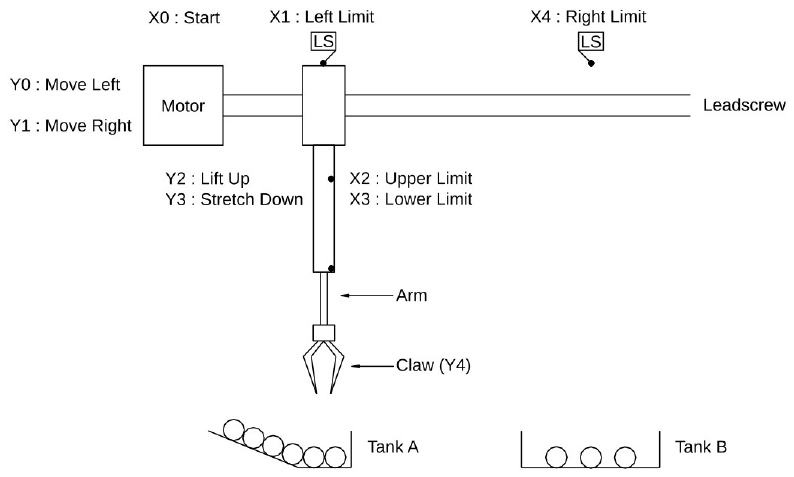
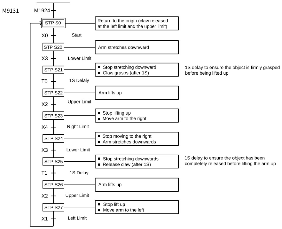
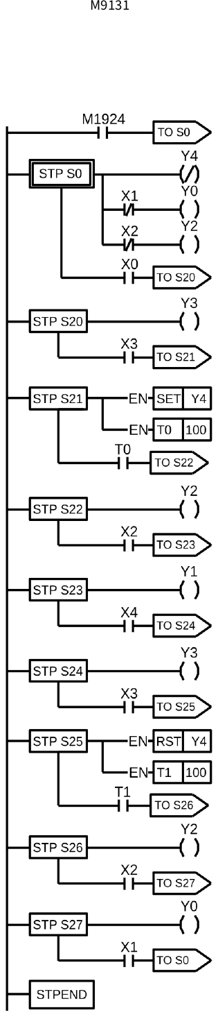
【Example 1】Grasp an object from tank A and put it in Tank B
|
|
Release claw Return to the left limit Return to the upper limit Turn the switch ON before moving to S20 Stretch arm downward Move to S21 after stretching to the lower limit Claw grasps (since the SET instruction is used, Y4 should remain ON after departing from STP S21) Divergent into S22 after 1S Lift the arm up Divergent into S23 after reaching the upper limit Move arm to the right Divergent into S24 after moving to the right limit Stretch the arm downward Divergent into S25 after stretching to the lower limit Release claw Delay for 1S Transfer into S26 after 1S Lift the arm up Divergent into S27 after reaching the upper limit Move the arm to the left Divergent into S0 after moving to the left limit (a complete cycle) |
【Example 2】Liquid Stirring Process
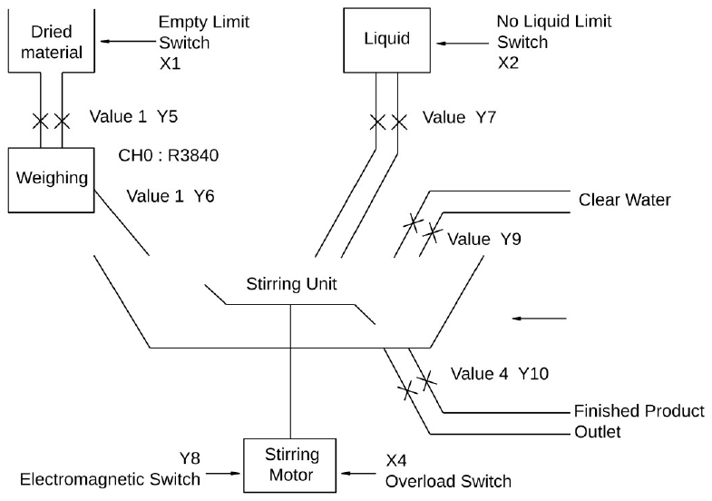
- Input Points:Empty limit switch X1
Noliquid linit switch X2
Empty limit switch X3
Over-load switch X4
Warning clear button X5
Start button X6
Water washing button X7
- Warning Indicators: Empty dried material Y1
Insufficient liquid Y2
Empty stirring unit Y3
Motor over-load Y4
- Output point: dry material feeding valve Y5
Dry feed valve Y6
Liquid feed valve Y7
Start motor solenoid valve Y8
Fresh water inlet valve Y9
Finished product feed valve Y100
- Weighing Output:CH0(R3840)
|
|
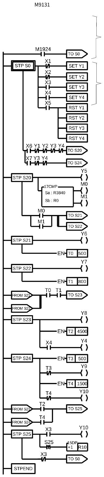
Warning indicators Reset warning Production start Water washing start Input weighing Status after weighing Divergent into S21 and S22 Add liquid to stirring unit Complete dried material and liquid input, transfer the status to S23 Stirring timer Wash stirring unit Input clean water Drain water out Output finished product and accumulate the cycle |
【Example 3】Pedestrian Crossing Lights
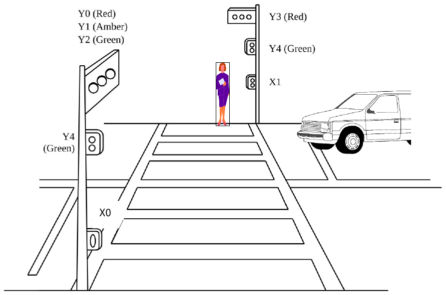
|
Pedestrian Push Button X0 Pedestrian Push Button X1 |
|
Road Red Light Y0 Road Amber light Y1 Road Green Light Y2 Pedestrian Crossing Red Light Y3 Pedestrian Crossing Green Light Y4 |
||
- Pedestrian Crossing Lights Control Process Diagram
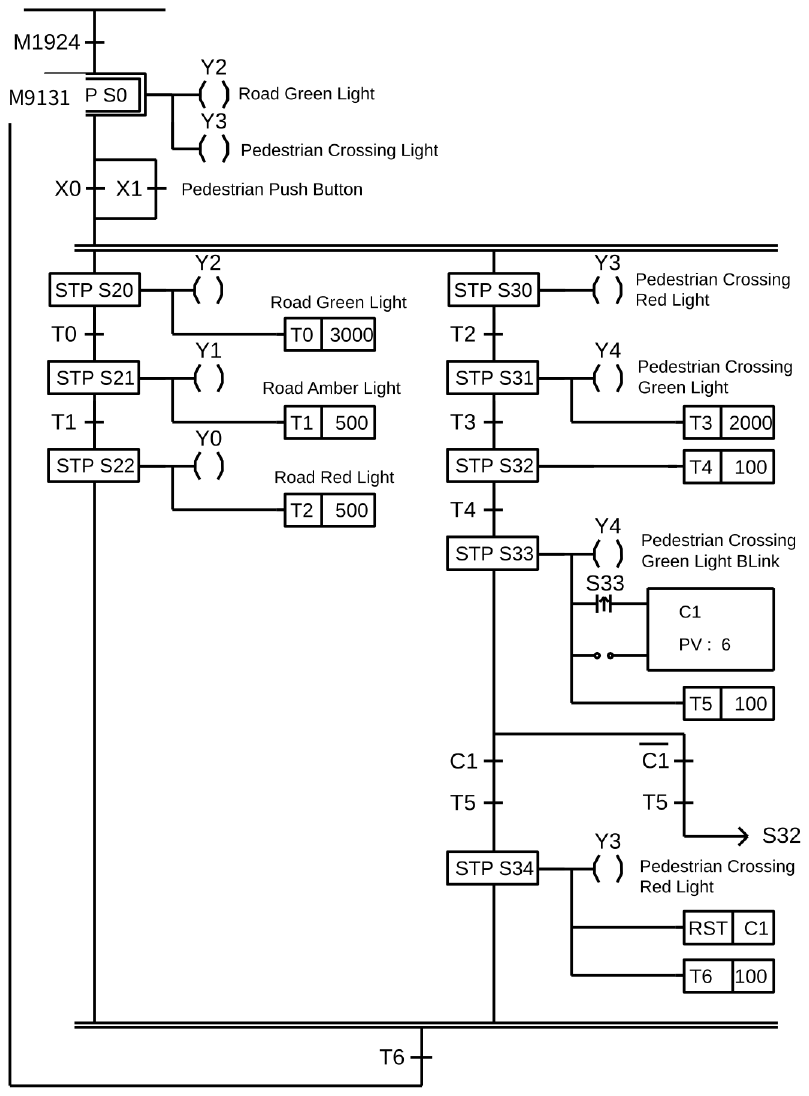
UperLogic |
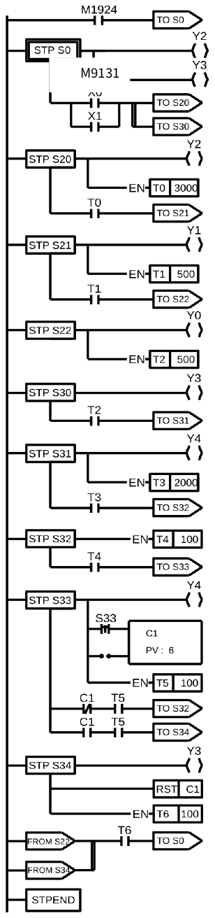
8-6 Syntax Check Error Codes for Step Instruction
The error codes for the usage of step instruction are as follows:
E51:TO(S0-S7) must begin with ORG instruction.
E52:TO(S20-S3103) can’t begin with ORG instruction.
E53:TO instruction without matched FROM instruction.
E54:To instruction must comes after TO, AND, OR, ANDLD or ORLD instruction.
E56:The instructions before FROM must be AND, OR, ANDLD or ORLD
E57:The instruction after FROM can’t be a coil or a function
E58:Coil or function must before FROM while in STEP network
E59:More than 8 TO# at same network.
E60:More than 8 FROM# at same network.
E61:TO(S0-S19) must locate at first row of the network.
E62:A contact occupies the location for TO instruction.
E71:Incomplete connection (should not happen)
E72:Duplicated TO Sxxxx instruction.
E73:Duplicated STP sxxxx instruction.
E74:Duplicated FROM sxxxx instruction.
E76:TP(S0~S19) without a matched STPEND or STPEND without a matched STP(S0~S19).
E77 :The previous network of STP(S0~S19) is not the only ORG~S19(S0~S19)
E78:TO(S20~S3103), STP (S20~S3103) or FROM instructions comes before or without STP(S0~S19).
E79:STP Sxxxx or FROM Sxxxx instructions comes before or without TO Sxxxx.
E80:FROM Sxxxx instruction comes before or without STP Sxxxx.
E81:The max level of branches must <=16.
E82:The max number of branches with same level must <=16.
E83:Not place the step instruction with TO->STP->FROM sequence.
E84:The definition of STP# sequence not follow the TO# sequence.
E85:Convergence do not match the corresponding divergence.
E86:Illegal usage of STP or FROM before convergent with TO instruction.
E87:STP# or FROM# comes before corresponding TO#.
E88:During this branch, STP# or FROM# comes before the corresponding TO#.
E89:FROM# comes before corresponding TO# or STP#.
E90:Invalid To# usage in the simultaneous branch.
E91:Last STP (S0~S19) has not been processed completely, use ORG, LBL, RTS, RTI, MCE, SKPE, FOR, NEXT, ENDD.
|
Version |
Date |
Description |
|
V1.0.3 |
2025/12/17 |
add Precaution to Disclaimers, Note add on page 7-37,7-39 |
|
V1.0.4 |
2026/1/29 |
Basic Function operand range , add description in Timer on page 6-1 ; Add something in Ladder Diagram : Timer , BSHF on page 6-3,6-26 ; Change some number in Example : BCD -> BIN , RST on page 6-63,6-13 . Advanced Function : Add or change Something in Ladder Diagram : QUEUE , STACK , FADD , FACOS on page 7-167,7-170,7-378,7-404 . Change or add some description : HSCTR , HSCTW , F→I , FDIV on page 7-131,7-129,7-49,7-383. |
|
V1.0.5 |
2026/2/5 |
Advanced Function : Add or change Something in Ladder Diagram : BITMV , BITRD , ROTR , Z-WR , MBCNT on page 7-40,7-44,7-49,7-62,7-179,7-202 . Change or add some description : BITMV,BYMV , ACCUMULATIVE TIMER on page 7-40,7-49,7-179. Make sure Floating point instruction operand range. |
|
V1.0.6 |
2026/2/12 |
Advanced Function : Make sure Artimetucal Operation ~ Shifting/Rotating , Table , Matrix instruction operand range. |
|
V1.0.7 |
2026/2/26 |
Advanced Function : Change Something in Ladder Diagram :<,<>,>= on page 7-248,7-250,7-252. |
|
V1.0.8 |
2026/3/5 |
Advanced Function : Change In Line Comparison and Data movement instruction operand range. |
|
V1.0.9 |
2026/3/12 |
Advanced Function : Change Zone Write(7-161), IMDIO(7-97,7-98), Communication and Flow Control instruction operand range. |
|
V1.0.10 |
2026/3/19 |
Advanced Function : Change IMDIO(7-98), PID Control, Slow up/Slow down and NC Positioning Instruction operand range. |
|
V1.0.11 |
2026/3/26 |
Advanced Function : Change Enable/Disable, NC Positioning II, Other Instruction operand range. Change description or title on page 7-226 and 7-294. |
|
V1.0.12 |
2026/4/2 |
Advanced Function : Change MFSTART~MFSYSRCTW operand range. |
|
V1.0.13 |
2026/4/22 |
Change MOD description. Advanced Function : Change MYSYSCAMR~MFPATHMOV operand range. |
|
V1.0.14 |
2026/5/14 |
Advanced Function : Change Something in Ladder Diagram : DIFD(6-23), DECREMENT(6-51); Change ST program : TOGG(6-30), DECREMENT(6-51),=(7-243),>(7-245),<(7-248),<>(7-251),>=(7-253),<=(7-255,7-256).Add FUN57 and FUN58. |
Tip: press ← → to switch chapters, Ctrl+K to search