2. Payload
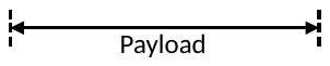
2.1. Format
- Query
|
Header |
ID |
Length |
STN(1) |
CMD(1) |
DATA(n) |
CRC |
Terminator |
- Response
|
Header |
ID |
Length |
STN(1) |
CMD(1) |
ERR(1) |
DATA (n) |
CRC |
Terminator |

- Parameter
|
Item |
Description |
Length |
Value |
|
STN |
The station number of a device. |
1 byte |
00H: broadcast 01H~FEH: slave station |
|
CMD |
The command to request device. |
1 byte |
Refer to 2.2 Command code |
|
ERR |
The status of response message. |
1 bytes |
Refer to 2.3 Error Code |
|
DATA |
Query data and response data varies with commands. |
n bytes |
2.2. The Description of Communication Command
- The description of communication command:
|
Command code |
Function description |
Length |
|
40H |
The gist read the system status of PLC |
– |
|
41H |
Control RUN/STOP of PLC |
– |
|
42H |
Single discrete control |
1 point |
|
43H |
The status reading of ENABLE/DISABLE of continuous discrete |
1~256 points |
|
44H |
The status reading of continuous discrete |
1~256 points |
|
45H |
Write the status to continuous discrete |
1~256 points |
|
46H |
Read the data from continuous registers |
1~64 words |
|
47H |
Write to continuous registers |
1~64 words |
|
48H |
Mixed read the random discrete status of register data |
1~64 points or words |
|
49H |
Mixed write the random discrete status of register data |
1~32 points or words |
|
4EH |
Loop back testing |
0~256 bytes |
|
53H |
The detail read the system status of PLC |
– |
2.3. The Communication Error Code of M series PLC
If the error happened in OS command, address, value area of software operation or hardware problem will cause the slave system can not process the command comes from master system. If there is error happened, slave system will respond the message to master system. No matter what command code or data the master system sends, the format of responding message is all the same. Including the required start code, end code and checksum value, the command code and station No. will be sent back to master system. The slave system will judge what kind of the error and respond the error code to master system.
- Following table is the response format of communication error of M series PLC:
|
Error code |
Description |
|
00H |
No Error |
|
02H |
Illegal value |
|
04H |
Illegal format, or communication command cannot be executed |
|
05H |
Can not run(Ladder Checksum error when run PLC) |
|
06H |
Can not run(PLC ID≠Ladder ID when run PLC) |
|
07H |
Can not run(Snytax check error when run PLC) |
|
09H |
Can not run(Function not supported) |
|
0AH |
Illegal address |
2.4. The Classification and Assignment of Components
|
Item |
Symbol |
Ascii Code |
Length |
|
Discrete |
X |
58H |
1 byte |
|
Y |
59H |
1 byte |
|
|
M |
4DH |
1 byte |
|
|
S |
53H |
1 byte |
|
|
T |
54H |
1 byte |
|
|
C |
43H |
1 byte |
|
|
16-Bit Register |
WX |
57H, 58H |
2 bytes |
|
WY |
57H, 59H |
2 bytes |
|
|
WM |
57H, 4DH |
2 bytes |
|
|
WS |
57H, 53H |
2 bytes |
|
|
WT |
57H, 54H |
2 bytes |
|
|
WC |
57H, 43H |
2 bytes |
|
|
RT |
52H, 54H |
2 bytes |
|
|
RC |
52H, 43H |
2 bytes |
|
|
R |
52H |
1 byte |
|
|
D |
44H |
1 byte |
|
|
F |
46H |
1 byte |
|
|
32-Bit Register |
DWX |
44H, 57H, 58H |
3 bytes |
|
DWY |
44H, 57H, 59H |
3 bytes |
|
|
DWM |
44H, 57H, 4DH |
3 bytes |
|
|
DWS |
44H, 57H, 53H |
3 bytes |
|
|
DWT |
44H, 57H, 54H |
3 bytes |
|
|
DWC |
44H, 57H, 43H |
3 bytes |
|
|
DRT |
44H, 52H, 54H |
3 bytes |
|
|
DRC |
44H, 52H, 43H |
3 bytes |
|
|
DR |
44H, 52H |
2 bytes |
|
|
DD |
44H, 44H |
2 bytes |
|
|
DF |
44H, 46H |
2 bytes |
2.5. Detail
2.5.1. Brief System Status Read [CMD:40H]
- Description
Read the system status of PLC
- Payload
- Query
|
STN(1) |
CMD(1) |
- Response
|
STN(1) |
CMD(1) |
ERR(1) |
STATUS (3) |
|
Parameter |
Description |
Value |
|
STATUS [1] |
PLC Status 1 |
B0: RUN/STOP B1: Battery low B2: Ladder checksum error/NORMAL B3: With Memory Card B4: WDT Timeout/NORMAL B5: SET ID/NOT SET ID B6: EMERGENCY STOP/NORMAL |
|
STATUS [2] |
PLC Status 2 |
Reserved |
|
STATUS [3] |
PLC Status 3 |
Reserved |
- Example
If the PLC is equipped with Memory Card and ID is set and PLC status is “RUN” under normal condition, the system status of PLC which MASTER read will be as following: (B5,B3, and B0 are 1 and the other are all 0 that the STATUS is 29H)。
- Query
|
01H |
40H |
- Response
|
01H |
40H |
00H |
29H |
00H |
00H |
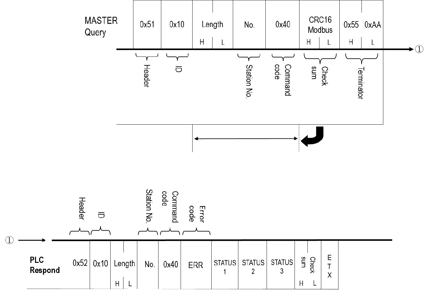
The command to be sent is as follows:
|
Command Message Segment |
Header |
ID |
Message Length |
Message Content |
CRC Checksum |
Terminator |
|
|
Content |
0x51 |
0x10 Fixed for use with the Binary communication protocol |
0x00 +0x02 |
Slave Station Number |
Command Code: 0x40 |
CRC16-Modbus calculation of "Message Length" + "Message Content" producing High byte + Low byte |
0x55+ 0xAA |
|
Message Length (Unit: Byte) |
1 |
1 |
2 |
1 |
1 |
2 |
2 |
|
Example: Slave Station Number: 01 |
0x51 |
0x10 |
0x00 +0x02 |
0x01 |
0x40 |
0xA1+ 0x84 |
0x55+ 0xAA |
The received and replied message is as follows:
|
Reply Message Segment |
Header |
ID |
Message Length |
Message Content |
CRC Checksum |
Terminator |
|||
|
Content |
0x52 |
0x10 Fixed for use with the Binary communication protocol |
0x00+0x06 |
Slave Station Number |
Command Code: 0x40 |
Error Code |
Status Code |
CRC16-Modbus calculation of "Message Length" + "Message Content" producing High byte + Low byte |
0x55+0xAA |
|
Message Length (Unit: Byte) |
1 |
1 |
2 |
1 |
1 |
1 |
3 |
2 |
2 |
|
Example: Slave Station Number: 01 |
0x52 |
0x10 |
0x00+0x06 |
0x01 |
0x40 |
0x00 |
0x01 +0x00 +0x00 |
0xD5+0x55 |
0x55+0xAA |
Error Code (1 Byte):
|
Value (Hexadecimal) |
Description |
|
0x00 |
No error occurred. |
|
0x02 |
Illegal value. |
|
0x04 |
Illegal format, or communication format cannot be executed. |
|
0x05 |
Unable to RUN PLC, checksum error in ladder diagram when PLC is running. |
|
0x06 |
Unable to RUN PLC, ladder ID and PLC ID do not match when PLC is running. |
|
0x07 |
Unable to RUN PLC, syntax error in PLC program when PLC is running. |
|
0x09 |
Unable to RUN PLC, function not supported. |
|
0x0A |
Illegal address. |
PLC Status Code (3 Byte):
|
Reply Message Segment |
Status Code 1 |
Status Code 2 |
Status Code 3 |
|
Content |
B0: RUN 1; STOP: 0 B1: Battery Low B2: Ladder diagram checksum error 1; Normal: 0 B3: SD card inserted or not B4: Watchdog timeout 1; Normal: 0 B5: ID is default 1; ID is not default: 0 B6: Emergency stop 1; Normal: 0 |
Reserved |
Reserved |
2.5.2. Run/Stop PLC [CMD: 41H]
- Description
Control the PLC RUN/STOP
- Payload
- Query
|
STN(1) |
CMD(1) |
CTRL(1) |
- Rsponse
|
STN(1) |
CMD(1) |
ERR(1) |
|
Parameter |
Description |
Value |
|
CTRL |
Control code |
00H: Stop 01H: Run |
- Example
Turn on PLC to “RUN”
- Query
|
01H |
41H |
01H |
- Rsponse
|
01H |
41H |
00H |
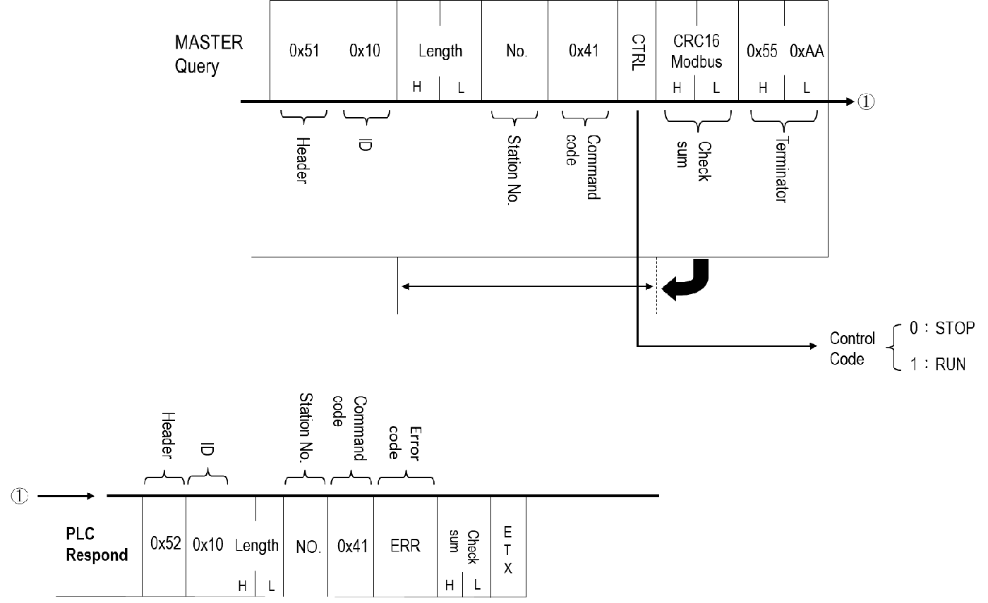
The command to be sent is as follows:
|
Command Message Segment |
Header |
ID |
Message Length |
Message Content |
CRC Checksum |
Terminator |
||
|
Content |
0x51 |
0x10 Fixed for use with the Binary communication protocol |
0x00 +0x03 |
Slave Station Number |
Command Code: 0x41 |
Control Code: |
CRC16-Modbus calculation of "Message Length" + "Message Content" producing High byte + Low byte |
0x55+0xAA |
|
Message Length (Unit: Byte) |
1 |
1 |
2 |
1 |
1 |
1 |
2 |
2 |
|
Example: Slave Station Number: 01, PLC STOP |
0x51 |
0x10 |
0x00+0x03 |
0x01 |
0x41 |
0x00 |
0x45+0xD4 |
0x55+0xAA |
Control Code (1 Byte):
|
Reply Message Segment |
Control Code |
|
Content |
0x00: STOP 0x01: RUN |
The received and replied message is as follows:
|
Reply Message Segment |
Header |
ID |
Message Length |
Message Content |
CRC Checksum |
Terminator |
||
|
Content |
0x52 |
0x10 Fixed for use with the Binary communication protocol |
0x00+0x03 |
Slave Station Number |
Command Code: 0x41 |
Error Code |
CRC16-Modbus calculation of "Message Length" + "Message Content" producing High byte + Low byte |
0x55+0xAA |
|
Message Length (Unit: Byte) |
1 |
1 |
2 |
1 |
1 |
1 |
2 |
2 |
|
Example: Slave Station Number: 01, PLC STOP |
0x52 |
0x10 |
0x00+0x03 |
0x01 |
0x41 |
0x00 |
0xD4+0x55 |
0x55+0xAA |
Error Code (1 Byte):
|
Value (Hexadecimal) |
Description |
|
0x00 |
No error occurred. |
|
0x02 |
Illegal value. |
|
0x04 |
Illegal format, or communication format cannot be executed. |
|
0x05 |
Unable to RUN PLC, checksum error in ladder diagram when PLC is running. |
|
0x06 |
Unable to RUN PLC, ladder ID and PLC ID do not match when PLC is running. |
|
0x07 |
Unable to RUN PLC, syntax error in PLC program when PLC is running. |
|
0x09 |
Unable to RUN PLC, function not supported. |
|
0x0A |
Illegal address. |
2.5.3. Single Discrete Control [CMD: 42H]
- Description
This command can control the appointed discrete to do ENABLE, DISABLE, SET, RESET four activities.
- Payload
- Query
|
STN(1) |
CMD(1) |
CTRL(1) |
TYPE(x) |
ADDR(2) |
- Response
|
STN(1) |
CMD(1) |
ERR(1) |
|
Parameter |
Description |
Value |
|
CTRL |
Control code |
01H: Disable 02H: Enable 03H: Set 04H: Reset |
|
TYPE |
The type of discrete |
Please refer to 2.4 Component, x: byte count |
|
ADDR |
The address of discrete |
- Example
The following communication format is the example to DISABLE the discrete X16.
- Query
|
01H |
42H |
01H |
58H |
00H |
10H |
|
↑ X16 |
|||||
- Response
|
01H |
42H |
00H |
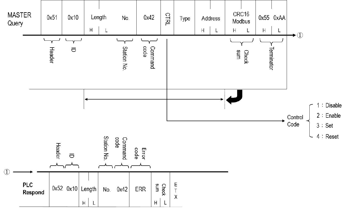
The command to be sent is as follows:
|
Command Message Segment |
Header |
ID |
Message Length |
Message Content |
CRC Checksum |
Terminator |
||||
|
Content |
0x51 |
0x10 Fixed for use with the Binary communication protocol |
1+1+1+n+2, where n depends on the length of Type |
Slave Station Number |
Command Code: 0x43 |
Control Code: |
Type |
Address of the single point |
CRC16-Modbus calculation of "Message Length" + "Message Content" producing High byte + Low byte |
0x55+0xAA |
|
Message Length (Unit: Byte) |
1 |
1 |
2 |
1 |
1 |
1 |
Referring Table |
2 |
2 |
2 |
|
Example: Slave Station Number: 01, Y100: SET |
0x51 |
0x10 |
0x00+0x06 |
0x01 |
0x42 |
0x03 |
0x59 |
0x00+0x64 |
0x8E+0x69 |
0x55+0xAA |
Control Code (1 Byte):
|
Reply Message Segment |
Control Code |
|
Content |
0x00 : Disable 0x01 : Enable 0x02 : Set 0x03 : Reset |
Type
|
Reply Message Segment |
Type(single point) |
Length |
|
Content |
0x58 : X |
1 |
|
0x59 : Y |
1 |
|
|
0x4D : M |
1 |
|
|
0x53 : S |
1 |
|
|
0x54 : T |
1 |
|
|
0x43 : C |
1 |
The received and replied message is as follows:
|
Reply Message Segment |
Header |
ID |
Message Length |
Message Content |
CRC Checksum |
Terminator |
||
|
Content |
0x52 |
0x10 Fixed for use with the Binary communication protocol |
0x00+0x03 |
Slave Station Number |
Command Code: 0x42 |
Error Code |
CRC16-Modbus calculation of "Message Length" + "Message Content" producing High byte + Low byte |
0x55+0xAA |
|
Message Length (Unit: Byte) |
1 |
1 |
2 |
1 |
1 |
1 |
2 |
2 |
|
Example: Slave Station Number: 01, PLC STOP |
0x52 |
0x10 |
0x00+0x03 |
0x01 |
0x42 |
0x00 |
0x24+0x55 |
0x55+0xAA |
Error Code (1 Byte):
|
Value (Hexadecimal) |
Description |
|
0x00 |
No error occurred. |
|
0x02 |
Illegal value. |
|
0x04 |
Illegal format, or communication format cannot be executed. |
|
0x05 |
Unable to RUN PLC, checksum error in ladder diagram when PLC is running. |
|
0x06 |
Unable to RUN PLC, ladder ID and PLC ID do not match when PLC is running. |
|
0x07 |
Unable to RUN PLC, syntax error in PLC program when PLC is running. |
|
0x09 |
Unable to RUN PLC, function not supported. |
|
0x0A |
Illegal address. |
2.5.4. Continuous Discrete Status Read [CMD: 43H]
- Description
Use this command to read the ENABLE/DISABLE status of the continuous discrete.
- Payload
- Query
|
STN(1) |
CMD(1) |
NUM(1) |
TYPE(x) |
ADDR(2) |
- Response
|
STN(1) |
CMD(1) |
ERR(1) |
STATUS 1(1) |
STATUS 2(1) |
… |
STATUS n(1) |
|
Parameter |
Description |
Value |
|
NUM |
The reading count of discrete |
00H: 256 01H~FFH: 1~255 |
|
TYPE |
The type of discrete |
Please refer to 2.4 Component, x: byte count |
|
ADDR |
The address of discrete |
|
|
STATUS |
ENABLE/DISABLE status |
n: the reading count of discrete, 00H: ENABLE 01H: DISABLE |
- Example
If Y10~Y16 of the continuous 7 discrete, Y10,Y12,Y16 are DISABLE and the others are all ENABLE, the PLC status of this command reading is as following.
- Query
|
01H |
43H |
07H |
59H |
00H |
0AH |
- Response
|
01H |
43H |
00H |
01H |
00H |
01H |
00H |
00H |
00H |
01H |
|
↑ Y10 |
↑ Y11 |
↑ Y12 |
↑ Y13 |
↑ Y14 |
↑ Y15 |
↑ Y16 |
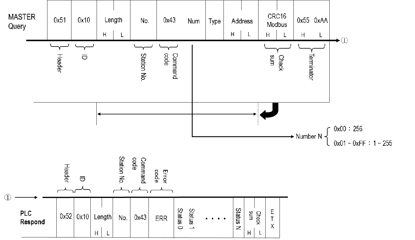
Sending the command:
|
Command Message Segment |
Header |
ID |
Message Length |
Message Content |
CRC Checksum |
Terminator |
||||
|
Content |
0x51 |
0x10 Fixed for use with the Binary communication protocol |
1+1+1+n+2, where n depends on the length of Type |
Slave Station Number |
Command Code: 0x43 |
Quantity |
Type |
Address of the single point |
CRC16-Modbus calculation of "Message Length" + "Message Content" producing High byte + Low byte |
0x55+0xAA |
|
Message Length (Unit: Byte) |
1 |
1 |
2 |
1 |
1 |
1 |
Referring Table |
2 |
2 |
2 |
|
Example: Slave Station Number: 01, Y100: SET |
0x51 |
0x10 |
0x00+0x06 |
0x01 |
0x43 |
0x04 |
0x58 |
0x00+0x00 |
0xE2+0xF6 |
0x55+0xAA |
Quantity (1 Byte):
|
Reply Message Segment |
Quantity |
|
Content |
0x00 :256 0x01~0xFF :1~255 |
Type Code (n Byte):
|
Reply Message Segment |
Type Code (Single Point) |
Length |
|
Content |
0x58 : X |
1 |
|
0x59 : Y |
1 |
|
|
0x4D : M |
1 |
|
|
0x53 : S |
1 |
|
|
0x54 : T |
1 |
|
|
0x43 : C |
1 |
Address (2 Byte):
|
Reply Message Segment |
Address |
|
Content |
0x00+0x00~0xFF+0xFF :1~65535 |
The received and replied messages are as follows:
|
Reply Message Segment |
Header |
ID |
Message Length |
Message Content |
CRC Checksum |
Terminator |
|||
|
Content |
0x52 |
0x10 Fixed for use with the Binary communication protocol |
1+1+1+n |
Slave Station Number |
Command Code: 0x43 |
Error code: 1 byte (refer to the table below for values) |
Disable/Enable status code * n |
CRC16-Modbus calculation of "Message Length" + "Message Content" producing High byte + Low byte |
0x55+0xAA |
|
Message Length (Unit: Byte) |
1 |
1 |
2 |
1 |
1 |
1 |
1*n |
2 |
2 |
|
Example: Station number: 01, Y0~Y3 are in Enable status |
0x52 |
0x10 |
0x00+0x07 |
0x01 |
0x43 |
0x00 |
0x01+0x01+ 0x01+0x01 |
0x49+0x55 |
0x55+0xAA |
Error Code (1 Byte):
|
Value (Hexadecimal) |
Description |
|
0x00 |
No error occurred. |
|
0x02 |
Illegal value. |
|
0x04 |
Illegal format, or communication format cannot be executed. |
|
0x05 |
Unable to RUN PLC, checksum error in ladder diagram when PLC is running. |
|
0x06 |
Unable to RUN PLC, ladder ID and PLC ID do not match when PLC is running. |
|
0x07 |
Unable to RUN PLC, syntax error in PLC program when PLC is running. |
|
0x09 |
Unable to RUN PLC, function not supported. |
|
0x0A |
Illegal address. |
Disable/Enable status code * n: (1*n Byte):
|
Status of indicated single point |
Description |
|
STATUS1 |
0x00: Enable 0x01: Disable |
|
STATUS2 |
0x00: Enable 0x01: Disable |
|
STATUS3 |
0x00: Enable 0x01: Disable |
.
.
.
|
STATUSn |
0x00: Enable 0x01: Disable |
2.5.5. Continuous Discrete Data Read [CMD: 44H]
- Description
Use this command to read the Set/Reset status of the continuous discrete.
- Payload
- Query
|
STN(1) |
CMD(1) |
NUM(1) |
TYPE(x) |
ADDR(2) |
- Response
|
STN(1) |
CMD(1) |
ERR(1) |
DATA 1(1) |
DATA 2(1) |
… |
DATA n(1) |
|
Parameter |
Description |
Value |
|
NUM |
The reading count of discrete |
00H: 256 01H~FFH: 1~255 |
|
TYPE |
The type of discrete |
Please refer to 2.4 Component, x: byte count |
|
ADDR |
The address of discrete |
|
|
DATA |
Set/Reset status |
n: the reading count of discrete, 00H: Reset 01H: Set |
- Example
If the status of X50, X52, X55 are all 0 and X51, X53, X54 are all 1, following is the status of reading the continuous 6 inputs(X50~X55)
- Query
|
01H |
44H |
06H |
58H |
00H |
32H |
- Response
|
01H |
44H |
00H |
00H |
01H |
00H |
01H |
01H |
00H |
|
↑ X50 |
↑ X51 |
↑ X52 |
↑ X53 |
↑ X54 |
↑ X55 |
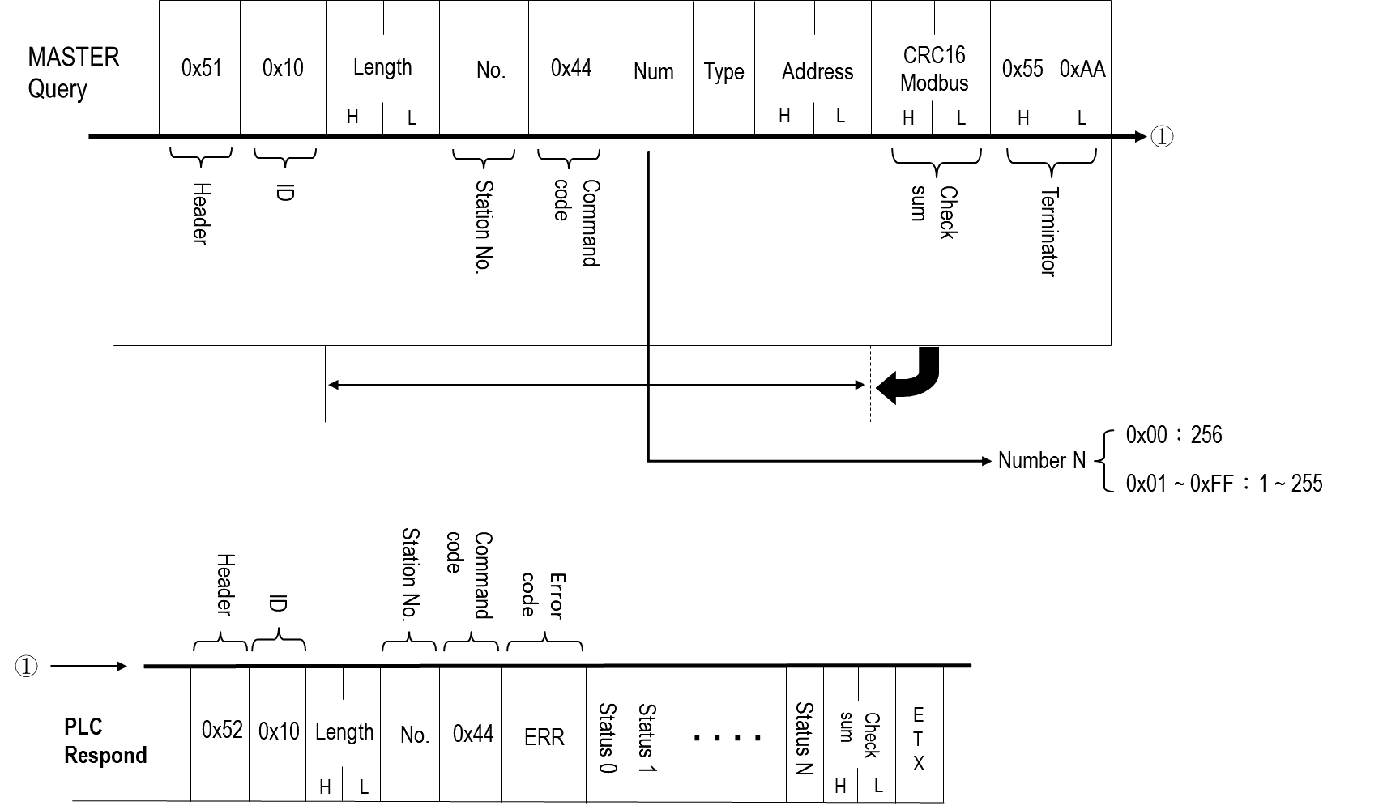
This command reads the status of specified single points.
|
Command Message Segment |
Header |
ID |
Message Length |
Message Content |
CRC Checksum |
Terminator |
||||
|
Content |
0x51 |
0x10 Fixed for use with the Binary communication protocol |
1+1+1+n+2, where n depends on the length of Type |
Slave Station Number |
Command Code: 0x44 |
Quantity |
Type |
Address of Single Point |
CRC16-Modbus calculation of "Message Length" + "Message Content" producing High byte + Low byte |
0x55+0xAA |
|
Message Length (Unit: Byte) |
1 |
1 |
2 |
1 |
1 |
1 |
Referring Table |
2 |
2 |
2 |
|
Example: Station number: 01, Y0~Y14 |
0x51 |
0x10 |
0x00+0x06 |
0x01 |
0x44 |
0x0F |
0x59 |
0x00+0x00 |
0x04+0xD2 |
0x55+0xAA |
Quantity (1 Byte):
|
Reply Message Segment |
Quantity |
|
Content |
0x00 :256 0x01~0xFF :1~255 |
Type Code (n Byte):
|
Reply Message Segment |
Type Code (Single Point) |
Length |
|
Content |
0x58 : X |
1 |
|
0x59 : Y |
1 |
|
|
0x4D : M |
1 |
|
|
0x53 : S |
1 |
|
|
0x54 : T |
1 |
|
|
0x43 : C |
1 |
Address (2 Byte):
|
Reply Message Segment |
Address |
|
Content |
0x00+0x00~0xFF+0xFF :1~65535 |
The received and replied message is as follows:
|
Reply Message Segment |
Header |
ID |
Message Length |
Message Content |
CRC Checksum |
Terminator |
|||
|
Content |
0x52 |
0x10 Fixed for use with the Binary communication protocol |
1+1+1+n should respond with the total length of the status code |
Slave Station Number |
Command Code: 0x44 |
Error code: Refer to the table below |
Status Code*n |
CRC16-Modbus calculation of "Message Length" + "Message Content" producing High byte + Low byte |
0x55+0xAA |
|
Message Length (Unit: Byte) |
1 |
1 |
2 |
1 |
1 |
1 |
1*n |
2 |
2 |
|
Example: Station number: 01, Y0~Y14: Reset |
0x52 |
0x10 |
0x00+0x12 |
0x01 |
0x44 |
0x00 |
(0x00)*15 |
0x89+0x55 |
0x55+0xAA |
Error Code (1 Byte):
|
Value (Hexadecimal) |
Description |
|
0x00 |
No error occurred. |
|
0x02 |
Illegal value. |
|
0x04 |
Illegal format, or communication format cannot be executed. |
|
0x05 |
Unable to RUN PLC, checksum error in ladder diagram when PLC is running. |
|
0x06 |
Unable to RUN PLC, ladder ID and PLC ID do not match when PLC is running. |
|
0x07 |
Unable to RUN PLC, syntax error in PLC program when PLC is running. |
|
0x09 |
Unable to RUN PLC, function not supported. |
|
0x0A |
Illegal address. |
Status Code (1*n Byte):
|
Status of indicated single point |
Description |
Length (Byte) |
|
STATUS1 |
0x00:Reset 0x01:Set |
1 |
|
STATUS2 |
0x00:Reset 0x01:Set |
1 |
|
STATUS3 |
0x00:Reset 0x01:Set |
1 |
.
.
.
|
STATUSn |
0x00:Reset 0x01:Set |
1 |
2.5.6. Continuous Discrete Data Write [CMD: 45H]
- Description
Use this command to write the Set/Reset status of the continuous discrete.
- Payload
- Query
|
STN(1) |
CMD(1) |
NUM(1) |
TYPE(x) |
ADDR(2) |
DATA 1(1) |
DATA 2(1) |
… |
DATA n(1) |
- Receive
|
STN(1) |
CMD(1) |
ERR(1) |
|
Parameter |
Description |
Value |
|
NUM |
The writing count of discrete |
00H: 256 01H~FFH: 1~255 |
|
TYPE |
The type of discrete |
Please refer to 2.4 Component, x: byte count |
|
ADDR |
The address of discrete |
|
|
DATA |
Set/Reset status |
n: the writing count of discrete, 00H: Reset 01H: Set |
- Example
Write the status to continuous 4 outputs(Y0~Y3), Y0 and Y3 are 1, Y1 and Y2 are 0
- Query
|
01H |
45H |
04H |
59H |
00H |
00H |
01H |
00H |
00H |
01H |
|
↑ Y0 |
↑ Y1 |
↑ Y2 |
↑ Y3 |
- Receive
|
01H |
45H |
00H |
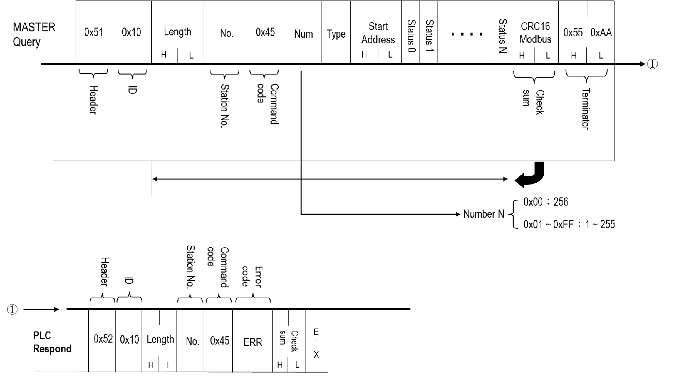
Sending Command as Follows:
|
Command Message Segment |
Header |
ID |
Message Length |
Message Content |
CRC Checksum |
Terminator |
|||||
|
Content |
0x51 |
0x10 Fixed for use with the Binary communication protocol |
1+1+1+n+2+m, where n depends on the length of Type, and m depends on the length of the status to be written. |
Slave Station Number |
Command Code: 0x45 |
Quantity |
Type |
Single Point Address |
Write in status*Quantity |
CRC16-Modbus calculation of "Message Length" + "Message Content" producing High byte + Low byte |
0x55+ 0xAA |
|
Message Length (Unit: Byte) |
1 |
1 |
2 |
1 |
1 |
1 |
N referring table |
2 |
m |
2 |
2 |
|
Example: Station number: 01, Y0, Y2: Reset Y1: SET |
0x51 |
0x10 |
0x00+0x09 |
0x01 |
0x45 |
0x03 |
0x59 |
0x00 +0x00 |
0x00+ 0x01+0x00 |
0x21 +0x0D |
0x55+ 0xAA |
Quantity (1 Byte):
|
Reply Message Segment |
Quantity |
|
Content |
0x00 :256 0x01~0xFF :1~255 |
Type Code (n Byte):
|
Reply Message Segment |
Type Code (Single Point) |
Length (Byte) |
|
Content |
0x58 : X |
1 |
|
0x59 : Y |
1 |
|
|
0x4D : M |
1 |
|
|
0x53 : S |
1 |
|
|
0x54 : T |
1 |
|
|
0x43 : C |
1 |
Address (2 Byte):
|
Reply Message Segment |
Address |
Length |
|
Content |
0x00+0x00~0xFF+0xFF :1~65535個 |
2 |
Write in Status Code (1*n Byte):
|
Status of indicated single point |
Description |
Length |
|
STATUS1 |
0x00:Reset 0x01:Set |
1 |
|
STATUS2 |
0x00:Reset 0x01:Set |
1 |
|
STATUS3 |
0x00:Reset 0x01:Set |
1 |
.
.
.
|
STATUSn |
0x00:Reset 0x01:Set |
1 |
The received and replied message is as follows:
|
Reply Message Segment |
Header |
ID |
Message Length |
Message Content |
CRC Checksum |
Terminator |
||
|
Content |
0x52 |
0x10 Fixed for use with the Binary communication protocol |
0x00+0x03 |
Slave Station Number |
Command Code: 0x45 |
Error code: Refer to the table below |
CRC16-Modbus calculation of "Message Length" + "Message Content" producing High byte + Low byte |
0x55+0xAA |
|
Message Length (Unit: Byte) |
1 |
1 |
2 |
1 |
1 |
1 |
2 |
2 |
|
Example: Slave Station Number 01 |
0x52 |
0x10 |
0x00+0x03 |
0x01 |
0x45 |
0x00 |
0x14+0x55 |
0x55+0xAA |
Error Code (1 Byte):
|
Value (Hexadecimal) |
Description |
|
0x00 |
No error occurred. |
|
0x02 |
Illegal value. |
|
0x04 |
Illegal format, or communication format cannot be executed. |
|
0x05 |
Unable to RUN PLC, checksum error in ladder diagram when PLC is running. |
|
0x06 |
Unable to RUN PLC, ladder ID and PLC ID do not match when PLC is running. |
|
0x07 |
Unable to RUN PLC, syntax error in PLC program when PLC is running. |
|
0x09 |
Unable to RUN PLC, function not supported. |
|
0x0A |
Illegal address. |
2.5.7. Continuous Register Data Read [CMD: 46H]
- Description
Use this command to read data from the continuous register.
- Payload
- Query
|
STN(1) |
CMD(1) |
NUM(1) |
TYPE(x) |
ADDR(2) |
- Response
|
STN(1) |
CMD(1) |
ERR(1) |
DATA 1(y) |
DATA 2(y) |
… |
DATA n(y) |
|
Parameter |
Description |
Value |
|
NUM |
The reading count of register |
01H~40H: 1~64 |
|
TYPE |
The type of register |
Please refer to 2.4 Component, x: byte count |
|
ADDR |
The address of register |
|
|
DATA |
The value of register |
n: the reading count of register y: byte count y = 2, 16-bit register |
- Example
Read the data of continuous 3 16-bit registers and start with R12.(R12,R13,R14)
- Query
|
01H |
46H |
03H |
52H |
00H |
0CH |
- Response
|
01H |
46H |
00H |
10H |
A5H |
7FH |
C4H |
00H |
01H |
|
↑ R12 |
↑ R13 |
↑ R14 |
||||||
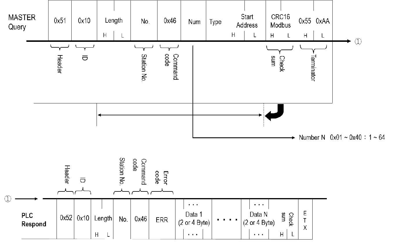
This command allows continuous reading of a specified quantity of data starting from designated registers.
|
Command Message Segment |
Header |
ID |
Message Length |
Message Content |
CRC Checksum |
Terminator |
||||
|
Content |
0x51 |
0x10 Fixed for use with the Binary communication protocol |
1+1+1+n+2, where n depends on the length of Type |
Slave Station Number |
Command Code: 0x46 |
Quantity |
Type |
Address of the Register |
CRC16-Modbus calculation of "Message Length" + "Message Content" producing High byte + Low byte |
0x55+0xAA |
|
Message Length (Unit: Byte) |
1 |
1 |
2 |
1 |
1 |
1 |
N referring table |
2 |
2 |
2 |
|
Example: Slave Station Number 01, R0~R1 |
0x51 |
0x10 |
0x00+0x06 |
0x01 |
0x46 |
0x02 |
0x52 |
0x00 + 0x00 |
0x0E+0x7C |
0x55+0xAA |
Quantity (1 Byte):
|
Reply Message Segment |
Quantity |
|
Content |
0x01~0x40 :1~64 |
Type Code (2 Byte/4 Byte):
|
Reply Message Segment |
Type Code (Single Point) |
Length (Byte) |
|
16 bit Register |
0x57+0x58 : WX |
2 |
|
0x57+0x59 : WY |
2 |
|
|
0x57+0x4D : WM |
2 |
|
|
0x57+0x53 : WS |
2 |
|
|
0x57+0x54 : WT |
2 |
|
|
0x57+0x43 : WC |
2 |
|
|
0x52+0x54 : RT |
2 |
|
|
0x52+0x43 : RC |
2 |
|
|
0x52 : R |
1 |
|
|
0x44 : D |
1 |
|
|
0x46 : F |
1 |
|
|
32 bit Register |
0x44+0x57+0x58 : DWX |
3 |
|
0x44+0x57+0x59 : DWY |
3 |
|
|
0x44+0x57+0x4D : DWM |
3 |
|
|
0x44+0x57+0x53 : DWS |
3 |
|
|
0x44+0x57+0x54 : DWT |
3 |
|
|
0x44+0x57+0x43 : DWC |
3 |
|
|
0x44+0x52 : DR |
2 |
|
|
0x44+0x44 : DD |
2 |
|
|
0x44+0x46 : DF |
2 |
Address (2 Byte):
|
Reply Message Segment |
Address |
Length |
|
Content |
0x00+0x00~0xFF+0xFF :1~65535 |
2 |
The received and replied message is as follows:
|
Reply Message Segment |
Header |
ID |
Message Length |
Message Content |
CRC Checksum |
Terminator |
|||
|
Content |
0x52 |
0x10 Fixed for use with the Binary communication protocol |
1+1+1+n, where n depends on the number of registers to be read |
Slave Station Number |
Command Code: 0x46 |
Error code: Refer to the table below |
Values in the register |
CRC16-Modbus calculation of "Message Length" + "Message Content" producing High byte + Low byte |
0x55+0xAA |
|
Message Length (Unit: Byte) |
1 |
1 |
2 |
1 |
1 |
1 |
1+1+1+N, where N varies depending on the number of registers set |
2 |
2 |
|
Example: Slave Station Number 01, R0=0xFF+0x55, R1=0xFF+0x4B |
0x52 |
0x10 |
0x00 +0x07 |
0x01 |
0x46 |
0x00 |
0xFF+0x55+ 0xFF+0x4B |
0xB3+0x55 |
0x55+0xAA |
Error Code (1 Byte):
|
Value (Hexadecimal) |
Description |
|
0x00 |
No error occurred. |
|
0x02 |
Illegal value. |
|
0x04 |
Illegal format, or communication format cannot be executed. |
|
0x05 |
Unable to RUN PLC, checksum error in ladder diagram when PLC is running. |
|
0x06 |
Unable to RUN PLC, ladder ID and PLC ID do not match when PLC is running. |
|
0x07 |
Unable to RUN PLC, syntax error in PLC program when PLC is running. |
|
0x09 |
Unable to RUN PLC, function not supported. |
|
0x0A |
Illegal address. |
Register Value (2*n/4*n Byte):
|
Status of indicated single point |
Description (16 Bit) |
Description (32 Bit) |
|
DATA1 |
0x00+0x00~ 0xFF+0xFF |
0x00+0x00+0x00+0x00~ 0xFF+0xFF+0xFF+0xFF |
|
DATA 2 |
0x00+0x00~ 0xFF+0xFF |
0x00+0x00+0x00+0x00~ 0xFF+0xFF+0xFF+0xFF |
|
DATA 3 |
0x00+0x00~ 0xFF+0xFF |
0x00+0x00+0x00+0x00~ 0xFF+0xFF+0xFF+0xFF |
.
.
.
|
DATA n |
0x00+0x00~ 0xFF+0xFF |
0x00+0x00+0x00+0x00~ 0xFF+0xFF+0xFF+0xFF |
2.5.8. Continuous Register Data Write [CMD: 47H]
- Description
Use this command to write data to continuous registers.
- Payload
- Query
|
STN(1) |
CMD(1) |
NUM(1) |
TYPE(x) |
ADDR(2) |
DATA 1(y) |
DATA 2(y) |
… |
DATA n(y) |
- Response
|
STN(1) |
CMD(1) |
ERR(1) |
|
Parameter |
Description |
Value |
|
NUM |
The writing count of register |
01H~40H: 1~64 |
|
TYPE |
The type of register |
Please refer to 2.4 Component, x: byte count |
|
ADDR |
The address of register |
|
|
DATA |
The value of register |
n: the reading count of register y: byte count y = 2, 16-bit register |
- Example
Input AAAAH to the 16-bit register WY16 and input 5555H to WY32. This is the format of input data to continuous register because WY16 and WY32 are continuous.
- Query
|
01H |
47H |
02H |
57H |
59H |
00H |
10H |
AAH |
AAH |
55H |
55H |
|
↑ WY16 |
↑ WY32 |
|||||||||
- Receive
|
01H |
47H |
00H |
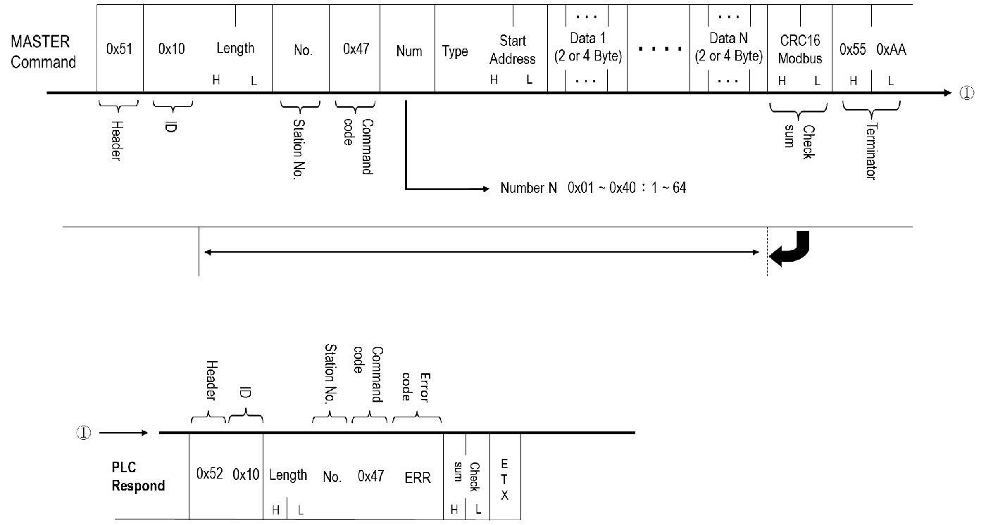
Sending command as follows:
|
Command Message Segment |
Header |
ID |
Message Length |
Message Content |
CRC Checksum |
Terminator |
|||||
|
Content |
0x51 |
0x10 Fixed for use with the Binary communication protocol |
1+1+1+n+m,where n depends on the length of the Type and m depends on the length of the data to be written |
Slave Station Number |
Command Code: 0x47 |
Quantity |
Type |
Address of the Register |
The data to be written into the registers |
CRC16-Modbus calculation of "Message Length" + "Message Content" producing High byte + Low byte |
0x55+ 0xAA |
|
Message Length (Unit: Byte) |
1 |
1 |
2 |
1 |
1 |
1 |
Referring Table |
2 |
m |
2 |
2 |
|
Example: Slave Station Number 01, R0~R2 Write (0xFF+0x55, 0xFF+0x4B, 0xFF+0x41) |
0x51 |
0x10 |
0x00 +0x0C |
0x01 |
0x47 |
0x03 |
0x52 |
0x00 +0x00 |
0xFF+ 0x55、0xFF+ 0x4B、0xFF+ 0x41 |
0xC4 + 0x16 |
0x55+ 0xAA |
Quantity (1 Byte):
|
Reply Message Segment |
Quantity |
|
Content |
0x01~0x40 :1~64 |
Type Code (2 Byte/4 Byte):
|
Reply Message Segment |
Type Code (Single Point) |
Length (Byte) |
|
16 bit Register |
0x57+0x58 : WX |
2 |
|
0x57+0x59 : WY |
2 |
|
|
0x57+0x4D : WM |
2 |
|
|
0x57+0x53 : WS |
2 |
|
|
0x57+0x54 : WT |
2 |
|
|
0x57+0x43 : WC |
2 |
|
|
0x52+0x54 : RT |
2 |
|
|
0x52+0x43 : RC |
2 |
|
|
0x52 : R |
1 |
|
|
0x44 : D |
1 |
|
|
0x46 : F |
1 |
|
|
32 bit Register |
0x44+0x57+0x58 : DWX |
3 |
|
0x44+0x57+0x59 : DWY |
3 |
|
|
0x44+0x57+0x4D : DWM |
3 |
|
|
0x44+0x57+0x53 : DWS |
3 |
|
|
0x44+0x57+0x54 : DWT |
3 |
|
|
0x44+0x57+0x43 : DWC |
3 |
|
|
0x44+0x52 : DR |
2 |
|
|
0x44+0x44 : DD |
2 |
|
|
0x44+0x46 : DF |
2 |
Address (2 Byte):
|
Reply Message Segment |
Address |
Length |
|
Content |
0x00+0x00~0xFF+0xFF :1~65535個 |
2 |
Register Value (2*n/4*n Byte):
|
Status of indicated single point |
Description (16 Bit) |
Description (32 Bit) |
|
DATA1 |
0x00+0x00~ 0xFF+0xFF |
0x00+0x00+0x00+0x00~ 0xFF+0xFF+0xFF+0xFF |
|
DATA 2 |
0x00+0x00~ 0xFF+0xFF |
0x00+0x00+0x00+0x00~ 0xFF+0xFF+0xFF+0xFF |
|
DATA 3 |
0x00+0x00~ 0xFF+0xFF |
0x00+0x00+0x00+0x00~ 0xFF+0xFF+0xFF+0xFF |
|
… |
||
|
DATA n |
0x00+0x00~ 0xFF+0xFF |
0x00+0x00+0x00+0x00~ 0xFF+0xFF+0xFF+0xFF |
The received and replied message is as follows:
|
Reply Message Segment |
Header |
ID |
Message Length |
Message Content |
CRC Checksum |
Terminator |
||
|
Content |
0x52 |
0x10 Fixed for use with the Binary communication protocol |
0x00 +0x03 |
Salve Station Number |
Command Code: 0x47 |
Error code: Refer to the table below |
CRC16-Modbus calculation of "Message Length" + "Message Content" producing High byte + Low byte |
0x55+ 0xAA |
|
Message Length (Unit: Byte) |
1 |
1 |
2 |
1 |
1 |
1 |
2 |
2 |
|
Example: Slave Station Number 01, PLC |
0x52 |
0x10 |
0x00 +0x03 |
0x01 |
0x47 |
0x00 |
0x46+ 0x74 |
0x55+ 0xAA |
Error Code (1 Byte):
|
Value (Hexadecimal) |
Description |
|
0x00 |
No error occurred. |
|
0x02 |
Illegal value. |
|
0x04 |
Illegal format, or communication format cannot be executed. |
|
0x05 |
Unable to RUN PLC, checksum error in ladder diagram when PLC is running. |
|
0x06 |
Unable to RUN PLC, ladder ID and PLC ID do not match when PLC is running. |
|
0x07 |
Unable to RUN PLC, syntax error in PLC program when PLC is running. |
|
0x09 |
Unable to RUN PLC, function not supported. |
|
0x0A |
Illegal address. |
2.5.9. Random Mixed Read [CMD: 48H]
- Description
Mixed read the random discrete status or register data.
- Payload
- Query
|
STN(1) |
CMD(1) |
NUM(1) |
TYPE 1(x) |
ADDR 1(2) |
TYPE 2(x) |
ADDR 2(2) |
… |
… |
|
TYPE n-1(x) |
ADDR n-1(2) |
TYPE n(x) |
ADDR n(2) |
- Response
|
STN(1) |
CMD(1) |
ERR(1) |
DATA 1(y) |
DATA 2(y) |
… |
DATA n(y) |
|
Parameter |
Description |
Value |
|
NUM |
The reading count of discrete or register |
01H~40H: 1~64 |
|
TYPE |
The type of register |
Please refer to 2.4 Component, x: byte count |
|
ADDR |
The address of register |
|
|
DATA |
The value of register |
n: the reading count of discrete or register y: byte count y = 1, discrete y = 2, 16-bit register |
- Example
Read the status and data of R1,Y9 and DWM0(i.e. M31~M0)
- Query
|
01H |
48H |
03H |
52H |
00H |
01H |
59H |
00H |
09H |
44H |
57H |
4DH |
00H |
00H |
|
↑ R1 |
↑ Y9 |
↑ DWM0 |
|||||||||||
- Receive
|
01H |
48H |
00H |
5CH |
34H |
01H |
00H |
35H |
47H |
BAH |
|
↑ R1 |
↑ Y9 |
↑ DWM0 |
|||||||
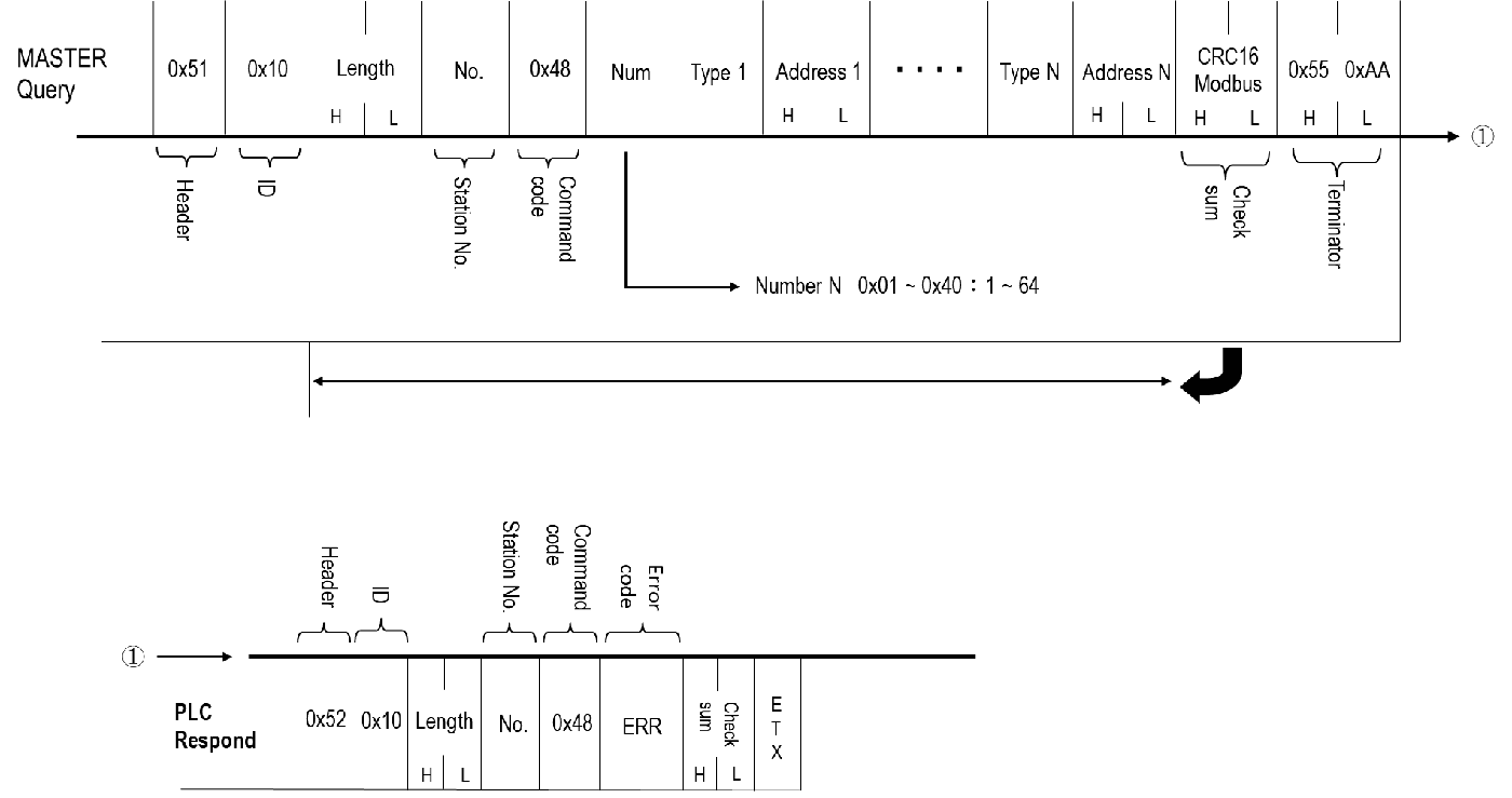
Sending command as follows:
|
Command Message Segment |
Header |
ID |
Message Length |
Message Content |
CRC Checksum |
Terminator |
|||||||
|
Content |
0x51 |
0x10 Fixed for use with the Binary communication protocol |
1+1+1+(n+2+…+m+2),where n and m depend on the length of the Type, and n can differ from m in type. |
Salve Station Number |
Command Code: 0x48 |
Quantity |
Typen |
Address n of register |
… |
Typem |
Address m of register |
CRC16-Modbus calculation of "Message Length" + "Message Content" producing High byte + Low byte |
0x55+ 0xAA |
|
Message Length (Unit: Byte) |
1 |
1 |
2 |
1 |
1 |
1 |
Referring Table |
2 |
Referring Table |
2 |
2 |
2 |
|
|
Example: Slave Station Number 01,DR15,D1 |
0x51 |
0x10 |
0x00=+0x0A |
0x01 |
0x48 |
0x02 |
0x44+0x52+0x00+0x0F+0x44+0x00+0x01 |
0x48 +0xB2 |
0x55+ 0xAA |
||||
Quantity (1 Byte):
|
Reply Message Segment |
Quantity |
|
Content |
0x01~0x40 :1~64 |
Type Code (1-Byte/2 Byte/4 Byte):
|
Reply Message Segment |
Type Code (Single Point) |
Length (Byte) |
|
Single Point |
0x58 : X |
1 |
|
0x59 : Y |
1 |
|
|
0x4D : M |
1 |
|
|
0x53 : S |
1 |
|
|
0x54 : T |
1 |
|
|
0x43 : C |
1 |
|
|
16 bit Register |
0x57+0x58 : WX |
2 |
|
0x57+0x59 : WY |
2 |
|
|
0x57+0x4D : WM |
2 |
|
|
0x57+0x53 : WS |
2 |
|
|
0x57+0x54 : WT |
2 |
|
|
0x57+0x43 : WC |
2 |
|
|
0x52+0x54 : RT |
2 |
|
|
0x52+0x43 : RC |
2 |
|
|
0x52 : R |
1 |
|
|
0x44 : D |
1 |
|
|
0x46 : F |
1 |
|
|
32 bit Register |
0x44+0x57+0x58 : DWX |
3 |
|
0x44+0x57+0x59 : DWY |
3 |
|
|
0x44+0x57+0x4D : DWM |
3 |
|
|
0x44+0x57+0x53 : DWS |
3 |
|
|
0x44+0x57+0x54 : DWT |
3 |
|
|
0x44+0x57+0x43 : DWC |
3 |
|
|
0x44+0x52 : DR |
2 |
|
|
0x44+0x44 : DD |
2 |
|
|
0x44+0x46 : DF |
2 |
Address (2 Byte):
|
Reply Message Segment |
Address |
Length |
|
Content |
0x00+0x00~0xFF+0xFF :1~65535 |
2 |
The received and replied message is as follows:
|
Reply Message Segment |
Header |
ID |
Message Length |
Message Content |
CRC Checksum |
Terminator |
|||||
|
Content |
0x52 |
0x10 Fixed for use with the Binary communication protocol |
1+1+1+(n+…+m) |
Salve Station Number |
Command Code: 0x48 |
Error code: Refer to the table below |
Value n in register |
… |
Value m in register |
CRC16-Modbus calculation of "Message Length" + "Message Content" producing High byte + Low byte |
0x55+ 0xAA |
|
Message Length (Unit: Byte) |
1 |
1 |
2 |
1 |
1 |
1 |
Referring table for the Type Length |
… |
Referring table for the Type Length |
2 |
2 |
|
Example: Slave Station Number 01, DR15=6, D1=0 |
0x52 |
0x10 |
0x00 +0x09 |
0x01 |
0x48 |
0x00+(0x99+0x99+0x00+0x00)+(0x00+0x00) |
0xDF+0x18 |
0x55+ 0xAA |
|||
Error Code (1 Byte):
|
Value (Hexadecimal) |
Description |
|
0x00 |
No error occurred. |
|
0x02 |
Illegal value. |
|
0x04 |
Illegal format, or communication format cannot be executed. |
|
0x05 |
Unable to RUN PLC, checksum error in ladder diagram when PLC is running. |
|
0x06 |
Unable to RUN PLC, ladder ID and PLC ID do not match when PLC is running. |
|
0x07 |
Unable to RUN PLC, syntax error in PLC program when PLC is running. |
|
0x09 |
Unable to RUN PLC, function not supported. |
|
0x0A |
Illegal address. |
Register Value (1*n/2*n/4*n Byte):
|
Status of indicated single point |
Description (Single Point) |
Description (16 Bit) |
Description (32 Bit) |
|
DATA1 |
0x00 : OFF 0x01 : ON |
0x00+0x00~ 0xFF+0xFF |
0x00+0x00+0x00+0x00~ 0xFF+0xFF+0xFF+0xFF |
|
DATA 2 |
0x00 : OFF 0x01 : ON |
0x00+0x00~ 0xFF+0xFF |
0x00+0x00+0x00+0x00~ 0xFF+0xFF+0xFF+0xFF |
|
DATA 3 |
0x00 : OFF 0x01 : ON |
0x00+0x00~ 0xFF+0xFF |
0x00+0x00+0x00+0x00~ 0xFF+0xFF+0xFF+0xFF |
.
.
.
|
DATA n |
0x00 : OFF 0x01 : ON |
0x00+0x00~ 0xFF+0xFF |
0x00+0x00+0x00+0x00~ 0xFF+0xFF+0xFF+0xFF |
2.5.10. Random Mixed Write [CMD: 49H]
- Description
Mixed write the random discrete status or register data.
- Payload
- Query
|
STN(1) |
CMD(1) |
NUM(1) |
TYPE 1(x) |
ADDR 1(2) |
DATA 1(y) |
|
TYPE 2(x) |
ADDR 2(2) |
DATA 2(y) |
… |
… |
… |
TYPE n(x) |
ADDR n(2) |
DATA n(y) |
- Response
|
STN(1) |
CMD(1) |
ERR(1) |
|
Parameter |
Description |
Value |
|
NUM |
The writing count of discrete or register |
01H~20H: 1~32 |
|
TYPE |
The type of register |
Please refer to 2.4 Component, x: byte count |
|
ADDR |
The address of register |
|
|
DATA |
The value of register |
n: the writing count of discrete or register y: byte count y = 1, discrete y = 2, 16-bit register |
- Example
Set the status of Y0 at 1, Y1 at 0, 16-bit register WM8 at 5555H, 32-bit register DR2 at FFH.
- Query
|
01H |
49H |
04H |
59H |
00H |
00H |
01H |
59H |
00H |
01H |
00H |
|
↑ Y0 |
↑ Y1 |
|||||||||
|
57H |
4DH |
00H |
08H |
55H |
55H |
44H |
52H |
00H |
02H |
00H |
00H |
00H |
FFH |
|
↑ WM8 |
↑ DR2 |
||||||||||||
- Receive
|
01H |
49H |
00H |
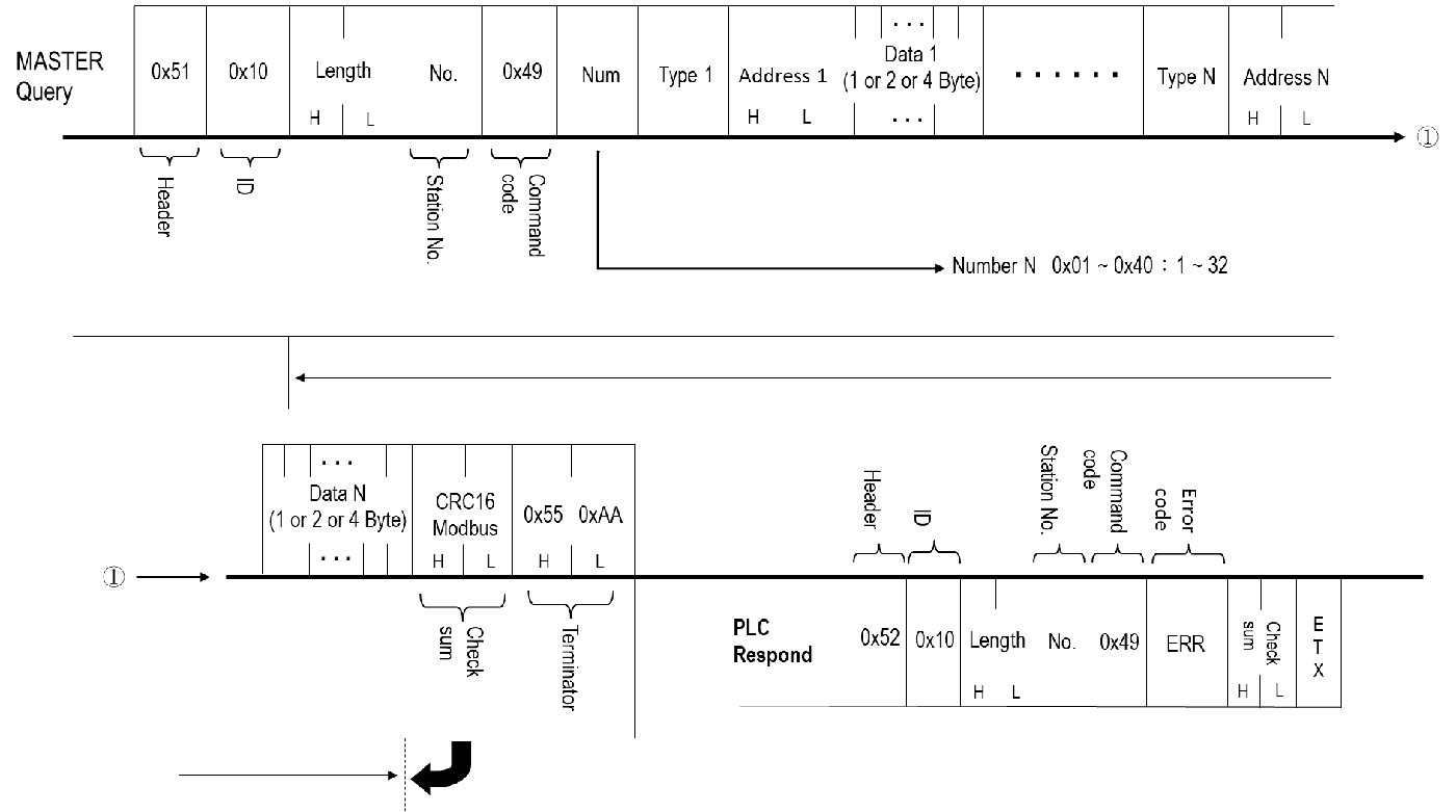
Sending command as follows:
|
Command Message Segment |
Header |
ID |
Message Length |
Message Content |
CRC Checksum |
Terminator |
|||||||||
|
Content |
0x51 |
0x10 Fixed for use with the Binary communication protocol |
1+1+1+(2+Type Length+Register Data Length), where n depends on the Type Length |
Slave Station Number |
Command Code: 0x49 |
Quantity |
Type 1 |
Address of register 1 |
Data to be written into Register 1 |
… |
Type n |
Register Address n |
Data to be written into Register n |
CRC16-Modbus calculation of "Message Length" + "Message Content" producing High byte + Low byte |
0x55+ 0xAA |
|
Message Length (Unit: Byte) |
1 |
1 |
2 |
1 |
1 |
1 |
Referring Table |
2 |
Referring table for the Type Length |
… |
Referring Table |
2 |
Referring table for the Type Length |
2 |
2 |
|
Example: Slave Station Number 01, WR0=15, R15=255 |
0x51 |
0x10 |
0x00 +0x10 |
0x01 |
0x49 |
0x02 |
0x44+0x52+0x00+0x00+0x00+0x00+0x00+0x00+0x52+0x00+0x0F+0x00+0x0F |
0x37 +0x89 |
0x55+ 0xAA |
||||||
Quantity (1 Byte):
|
Reply Message Segment |
Quantity |
|
Content |
0x01~0x40 :1~64 |
Type Code (1-Byte/2 Byte/4 Byte):
|
Reply Message Segment |
Type Code (Single Point) |
Length (Byte) |
|
Single Point |
0x58 : X |
1 |
|
0x59 : Y |
1 |
|
|
0x4D : M |
1 |
|
|
0x53 : S |
1 |
|
|
0x54 : T |
1 |
|
|
0x43 : C |
1 |
|
|
16 bit Register |
0x57+0x58 : WX |
2 |
|
0x57+0x59 : WY |
2 |
|
|
0x57+0x4D : WM |
2 |
|
|
0x57+0x53 : WS |
2 |
|
|
0x57+0x54 : WT |
2 |
|
|
0x57+0x43 : WC |
2 |
|
|
0x52+0x54 : RT |
2 |
|
|
0x52+0x43 : RC |
2 |
|
|
0x52 : R |
1 |
|
|
0x44 : D |
1 |
|
|
0x46 : F |
1 |
|
|
32 bit Register |
0x44+0x57+0x58 : DWX |
3 |
|
0x44+0x57+0x59 : DWY |
3 |
|
|
0x44+0x57+0x4D : DWM |
3 |
|
|
0x44+0x57+0x53 : DWS |
3 |
|
|
0x44+0x57+0x54 : DWT |
3 |
|
|
0x44+0x57+0x43 : DWC |
3 |
|
|
0x44+0x52 : DR |
2 |
|
|
0x44+0x44 : DD |
2 |
|
|
0x44+0x46 : DF |
2 |
Address (2 Byte):
|
Reply Message Segment |
Address |
Length |
|
Content |
0x00+0x00~0xFF+0xFF :1~65535 |
2 |
Register Value (1*n/2*n/4*n Byte):
|
Status of indicated single point |
Description (Single Point) |
Description (16 Bit) |
Description (32 Bit) |
|
DATA1 |
0x00 : OFF 0x01 : ON |
0x00+0x00~ 0xFF+0xFF |
0x00+0x00+0x00+0x00~ 0xFF+0xFF+0xFF+0xFF |
|
DATA 2 |
0x00 : OFF 0x01 : ON |
0x00+0x00~ 0xFF+0xFF |
0x00+0x00+0x00+0x00~ 0xFF+0xFF+0xFF+0xFF |
|
DATA 3 |
0x00 : OFF 0x01 : ON |
0x00+0x00~ 0xFF+0xFF |
0x00+0x00+0x00+0x00~ 0xFF+0xFF+0xFF+0xFF |
.
.
.
|
DATA n |
0x00 : OFF 0x01 : ON |
0x00+0x00~ 0xFF+0xFF |
0x00+0x00+0x00+0x00~ 0xFF+0xFF+0xFF+0xFF |
The received and replied message is as follows:
|
Reply Message Segment |
Header |
ID |
Message Length |
Message Content |
CRC Checksum |
Terminator |
||
|
Content |
0x52 |
0x10 Fixed for use with the Binary communication protocol |
0x00 +0x03 |
Salve Station Number |
Command Code: 0x49 |
Error code: Refer to the table below |
CRC16-Modbus calculation of "Message Length" + "Message Content" producing High byte + Low byte |
0x55+ 0xAA |
|
Message Length (Unit: Byte) |
1 |
1 |
2 |
1 |
1 |
1 |
2 |
2 |
|
Example: Slave Station Number 01 |
0x52 |
0x10 |
0x00 +0x03 |
0x01 |
0x49 |
0x00 |
0x42+0x 14 |
0x55+ 0xAA |
Error Code (1 Byte):
|
Value (Hexadecimal) |
Description |
|
0x00 |
No error occurred. |
|
0x02 |
Illegal value. |
|
0x04 |
Illegal format, or communication format cannot be executed. |
|
0x05 |
Unable to RUN PLC, checksum error in ladder diagram when PLC is running. |
|
0x06 |
Unable to RUN PLC, ladder ID and PLC ID do not match when PLC is running. |
|
0x07 |
Unable to RUN PLC, syntax error in PLC program when PLC is running. |
|
0x09 |
Unable to RUN PLC, function not supported. |
|
0x0A |
Illegal address. |
2.5.11. Loop Back [CMD: 4EH]
- Description
This command makes PLC respond all test data back to Master. It is only for testing the communication condition between Master and PLC and it will not influence the PLC function.
- Payload
- Query
|
STN(1) |
CMD(1) |
DATA(n) |
- Rsponse
|
STN(1) |
CMD(1) |
DATA(n) |
|
Parameter |
Description |
Value |
|
DATA |
Testing data |
n: data length (bytes) |
- Example
Use this command to send the data〝ABCDEFG〞from Master to PLC to rest weather the PLC respond normally.
- Query
|
01H |
4EH |
41H |
42H |
43H |
44H |
45H |
46H |
47H |
- Rsponse
|
01H |
4EH |
41H |
42H |
43H |
44H |
45H |
46H |
47H |
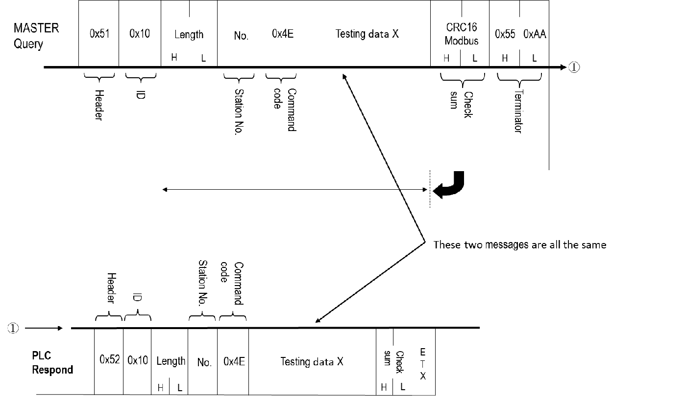
Sending command as follows:
|
Message Section |
Start Character |
ID |
Message Length |
Message Content |
CRC Check |
End Character |
||
|
Content |
0x51 |
0x10 Fixed for Binary communication protocol |
1 + 1 + n, where n depends on the length of test data |
Slave Station Number |
Command Code: 0x4E |
Test Data |
CRC16-Modbus calculation of "Message Length" + "Message Content" producing High byte + Low byte |
0x55+ 0xAA |
|
Message Length (Bytes) |
1 |
1 |
2 |
1 |
1 |
Test Data Length |
2 |
2 |
|
Example: Slave Station Number: 01, Test Code 0xFF + 0xFF |
0x51 |
0x10 |
0x00 +0x04 |
0x01 |
0x4E |
0xFF+0xFF |
0x91 +0x80 |
0x55+ 0xAA |
Register Value (n Byte):
|
Status of the indicated single point |
Description (Single Point) |
|
DATA |
Test Data |
The received and replied message is as follows:
|
Reply Message Section |
Start Character |
ID |
Message Length |
Message Content |
CRC Check |
End Character |
||
|
Content |
0x52 |
0x10 Fixed for Binary communication protocol |
0x00 +0x03 |
Slave Station Number |
Command Code: 0x4E |
Test Data Resend |
CRC16-Modbus calculation of "Message Length" + "Message Content" producing High byte + Low byte |
0x55+ 0xAA |
|
Message Length (Bytes) |
1 |
1 |
2 |
1 |
1 |
Testing data length |
2 |
2 |
|
Example: Slave Station Number: 01, Test Code 0xFF + 0xFF |
0x52 |
0x10 |
0x00 +0x04 |
0x01 |
0x4E |
0xFF+0xFF |
0x91 +0x80 |
0x55+ 0xAA |
Register Value (n Byte):
|
Status of the indicated single point |
Description (Single Point) |
|
DATA |
Test Data |
Error Code (1 Byte):
|
Value (Hexadecimal) |
Description |
|
0x00 |
No error occurred. |
|
0x02 |
Illegal value. |
|
0x04 |
Illegal format, or communication format cannot be executed. |
|
0x05 |
Unable to RUN PLC, checksum error in ladder diagram when PLC is running. |
|
0x06 |
Unable to RUN PLC, ladder ID and PLC ID do not match when PLC is running. |
|
0x07 |
Unable to RUN PLC, syntax error in PLC program when PLC is running. |
|
0x09 |
Unable to RUN PLC, function not supported. |
Command Code (1 Byte):
|
Value (Hexadecimal) |
Description |
Command Length |
Control Data Length |
|
0x40 |
PLC Status Inquiry |
1 |
– |
|
0x41 |
PLC RUN/STOP Ctrol |
1 |
– |
|
0x42 |
Single Point Operation Control |
1 |
1 |
|
0x43 |
Read Enable/Disable Status of Multiple Consecutive Points |
1 |
1~256 |
|
0x44 |
Read Status of Multiple Consecutive Points |
1 |
1~256 |
|
0x45 |
Write Status to Multiple Consecutive Points |
1 |
1~256 |
|
0x46 |
Read Data from Multiple Consecutive Registers |
1 |
1~64 |
|
0x47 |
Write Data to Multiple Consecutive Registers |
1 |
1~64 |
|
0x48 |
Read Mixed Data of Multiple Arbitrary Points or Registers |
1 |
1~64 |
|
0x49 |
Write Mixed Data of Multiple Arbitrary Points or Registers |
1 |
1~32 |
|
0x4E |
Test Return |
1 |
0~256 |
Revision History
|
Version |
Date |
Description |
|
V1.0 |
2024/12/23 |
First version |
Tip: press ← → to switch chapters, Ctrl+K to search