1. Message
M series PLC is defined as slaves in the communication with peripheral devices that are always defined as masters when communicate with M series PLC.
All the peripheral devices send the message when communicate with M series PLC and its respond when receive the message from masters.
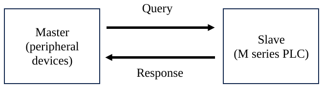
M series PLC communication ports support Type C, COM1 and COM2, as well as TCP/IP communication.
 The format of the command message sent by the master is as follows:
|
Command Message Segment |
Headler |
ID |
Length |
Payload |
CRC |
Terminator |
|
|
Content |
0x51 |
0x10 Fixed for use with the Binary communication protocol |
N(Based on the message length.) |
M(Based on the issued commands and their content.) The next section will explain the message structure. |
CRC16-Modbus calculation of "Message Length" + "Message Content" producing High byte + Low byte |
0x55+ 0xAA |
|
|
Hight byte |
Low byte |
||||||
|
Message length (unit: Byte) |
1 |
1 |
2 |
M |
2 |
2 |
|
➀ Headler: The beginning of a message. The command and response messages have the same starting characters "0x51" (hexadecimal), which the M series PLC will use to identify the beginning of the transmitted data.
➁ ID: The number for the binary communication protocol is fixed at 0x10.
➂ Length: Total bytes of payload.
➃ Payload: The data comprises a command message or a response message.
➄ CRC: The M series PLC uses CRC16-Modbus for verification. After calculating the CRC16-Modbus checksum on the "length" and "payload," a checksum is generated in the sequence of High byte + Low byte. The detailed algorithm is as follows:
(1) Set the CRC calculation output variable to an initial value of 0xFFFF (2 bytes).
(2) Perform an XOR operation between the 1-byte data to be calculated and the lower
byte of the CRC output variable.
(3) Create a FOR loop and check the LSB (Least Significant Bit) of the CRC output variable a
total of 8 times:
◎ If the rightmost LSB is 1, right-shift the CRC output variable by one bit and perform an
XOR operation with 0xA001.
◎ If the rightmost LSB is 0, simply right-shift the CRC output variable by one bit.
(4) After completing the CRC calculation for this byte, return to step 2 and retrieve the
next data byte to continue the CRC calculation until all data bytes are processed.
(5) Swap the high and low bytes of the CRC output variable, which will then be the final
checksum.
➅ Terminator: The end of a message. The command and response messages have the same ending characters: "0x55" (hexadecimal) and "0xAA" (hexadecimal). The M PLC uses these characters to recognize the end of the transmitted data.
 The format of the response message from the slave after receiving the command is as follows:
|
Reply Message Segment |
Headler |
ID |
Length |
Payload |
CRC |
Terminator |
|
|
Content |
0x52 |
0x10 Fixed for use with the Binary communication protocol |
N(Based on the message length.) |
M(Based on the issued commands and their content.) The next section will explain the message structure. |
CRC16-Modbus calculation of "Message Length" + "Message Content" producing High byte + Low byte |
0x55+ 0xAA |
|
|
Hight byte |
Low byte |
||||||
|
Message length (unit: Byte) |
1 |
1 |
2 |
M |
2 |
2 |
|
➀ Headler: The beginning of a message. The command and response messages have the same starting characters "0x52" (hexadecimal), which the M series PLC will use to identify the beginning of the transmitted data.
➁ ID: The number for the binary communication protocol is fixed at 0x10.
➂ Length: Total bytes of payload.
➃ Payload: The data comprises a command message or a response message.
➄ CRC: The M series PLC uses CRC16-Modbus for verification. After calculating the CRC16-Modbus checksum on the "length" and "payload," a checksum is generated in the sequence of High byte + Low byte. The detailed algorithm is as follows:
(1) Set the CRC calculation output variable to an initial value of 0xFFFF (2 bytes).
(2) Perform an XOR operation between the 1-byte data to be calculated and the lower
byte of the CRC output variable.
(3) Create a FOR loop and check the LSB (Least Significant Bit) of the CRC output variable a
total of 8 times:
◎If the rightmost LSB is 1, right-shift the CRC output variable by one bit and perform an
XOR operation with 0xA001.
◎If the rightmost LSB is 0, simply right-shift the CRC output variable by one bit.
(4) After completing the CRC calculation for this byte, return to step 2 and retrieve the
next data byte to continue the CRC calculation until all data bytes are processed.
(5) Swap the high and low bytes of the CRC output variable, which will then be the final
checksum.
➅ Terminator: The end of a message. The command and response messages have the same ending characters: "0x55" (hexadecimal) and "0xAA" (hexadecimal). The M PLC uses these characters to recognize the end of the transmitted data.
- Query
|
Header(1) 51H |
ID(1) 10H |
Length (2) |
Payload (length) |
CRC (2) |
Terminator(2) 55AAH |
- Response
|
Header(1) 52H |
ID(1) 10H |
Length (2) |
Payload (length) |
CRC (2) |
Terminator(2) 55AAH |
- Parameter
|
Item |
Length |
Description |
Value |
|
Header |
1 byte |
The beginning of a message. |
51H: Query 52H: Respons |
|
ID |
1 byte |
Specify the payload frame to be used |
10H: default value |
|
Length |
2 bytes |
Total bytes of payload |
|
|
Payload |
n bytes |
The data comprises a query message or a response message. |
Refer to 2 |
|
CRC |
2 bytes |
Use CRC-16 Modbus, calculating range include length and payload |
|
|
Terminator |
2 bytes |
The end of a message. |
55AAH: default terminator |
Tip: press ← → to switch chapters, Ctrl+K to search