2-1 Special Register Reference
Special Register Reference
|
MPLC Relay |
Write Permissions |
FBS Relay |
||||||
|
Relay No. |
Function |
Lable Abbreviation |
Description |
Relay No. |
Function |
Description |
||
|
STOPPED – CONTROL DISABLED |
M9120 |
Emergency Stop control |
EMERGENCY_STOP_CTRL |
1:PLC Stop |
RW |
M1912 |
Emergency Stop control |
1:In STOP mode, all outputs are turned OFF. The system automatically recovers (resets to 0) upon a power cycle or when a RUN command is issued again. |
|
M9121 |
Disable External Output Control |
– |
– |
RW |
M1913 |
Disable External Output Control |
1:Disable all outputs (all output terminals are OFF), but the internal status of Y0 to Y255 remains unaffected. |
|
|
M9122 |
Disable Status Retent Select |
DISABLE_STATUS_RETENT_CTRL |
1:Disable |
RW |
M2001 |
Disable Status Retent Select |
When M2001 is disabled and forced ON, the disable/enable status of all contacts will remain unchanged each time the power is turned on or when the PLC transitions from STOP to RUN. When M2001 is set to 0, all contacts will reset to the enabled state each time the power is turned on or when the PLC transitions from STOP to RUN. During test run (commissioning), if you need to disable contacts and retain their state across power cycles or stop status, disable M2001 and force it ON. After the test run is completed, be sure to enable M2001 and force it OFF. |
|
|
CLEAR CONTROL |
M9123 |
Clear Retentive Registers |
CLR_NON_RETENT_RELAY |
1:Clear |
RW |
M1914 |
Clear Retentive Registers |
1:Clear |
|
M9124 |
Clear Retentive Registers |
CLR_RETENT_RELAY |
1:Clear |
RW |
M1915 |
Clear Retentive Registers |
1:Clear |
|
|
M9125 |
Clear Non-Retentive Registers |
CLR_NON_RETENT_REG |
1:Clear |
RW |
M1916 |
Clear Non-Retentive Registers |
1:Clear |
|
|
M9126 |
Clear Retentive Registers |
CLR_RETENT_REG |
1:Clear |
RW |
M1917 |
Clear Retentive Registers |
1:Clear |
|
|
– |
– |
– |
– |
– |
M1918 |
Master Control(MC)Select |
0:When the master control loop transitions from 0 to 1, pulse-type application instructions inside the loop are executed only once. 1:When the master control loop transitions from 0 to 1, all pulse-type application instructions inside the loop are executed. |
|
|
– |
– |
– |
– |
– |
M1919 |
Output memory selection for application instruction-s |
0:When the application instruction is not executed, its outputs are retentive. 1:When the application instruction is not executed, its outputs are retentive. |
|
|
Pulse Signal |
M9127 |
0.01s Clock pulse |
CLK_PULSE_0_01S |
Picture one: T is 0.01 sec for M9127 T is 0.1 sec for M9128 T is 1 sec for M9129 T is 60sec for M9130 |
RO |
M1920 |
0.01s Clock pulse |
Picture one: T is 0.01 sec for M1920 T is 0.1 sec for M1921 T is 1 sec for M1922 T is 60 sec for M1923 |
|
M9128 |
0.1s Clock pulse |
CLK_PULSE_0_1S |
RO |
M1921 |
0.1s Clock pulse |
|||
|
M9129 |
1s Clock pulse |
CLK_PULSE_1S |
RO |
M1922 |
1s Clock pulse |
|||
|
M9130 |
60s Clock pulse |
CLK_PULSE_60S |
RO |
M1923 |
60s Clock pulse |
|||
|
M9131 |
Initial Pulse (First Scan) |
CLK_PULSE_INIT |
Picture two: t is scan time |
RO |
M1924 |
Initial Pulse (First Scan) |
Picture two: t is scan time |
|
|
M9132 |
Scan Cyclic Pulse |
CLK_PULSE_SCAN |
Picture three: t is scan time |
RO |
M1925 |
Scan Cyclic Pulse |
Picture three: t is scan time |
|
|
M9133 |
PLC Working Mode |
PLC_WORKING_MODE |
0,PLC Work in STOP Mode 1,PLC Work in RUN Mode |
RO |
M1926 |
PLC Working Mode |
0:PLC Work in STOP mode 1:PLC Work in RUN mode " |
|
|
– |
– |
– |
– |
– |
M1927 |
CTS input status of Port 1 |
0:CTS True (ON) 1:CTS False (OFF),When Port 1 is used to connect a printer or modem, this signal can be combined with a timer to detect whether the printer or modem is ready (ON) |
|
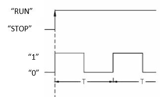
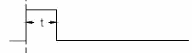
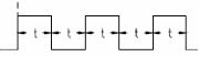
Picture one Picture two Picture three
Special Relay Reference
|
MPLC Relay |
Write Permissions |
FBS Relay |
||||||
|
Relay No. |
Function |
Lable Abbreviation |
Description |
Relay No. |
Function |
Description |
||
|
WRONG MESSAGE |
M9134 |
System Fault Alarm |
CPU_ABNL_WARNING |
1 : Indicates that the expansion module is missing or the I/O point limit has been exceeded. |
RO |
M1930 |
Expansion unit not connected or I/O points exceeded. |
1:Indicates expansion unit not connected or I/O points exceeded. |
|
– |
– |
– |
– |
– |
M1931 |
Immediate I/O points exceed the main unit’s range. |
1:Indicates immediate I/O points in the program exceed the CPU’s I/O range → CPU cannot RUN. |
|
|
– |
– |
– |
– |
– |
M1933 |
System STACK error. |
1:Indicates system STACK error. |
|
|
PORT1~PORT2 CONTROL |
M9135 |
Port1 operation indicator (READY) |
COM_BUSY_P1 |
0:Port 1 is in use. 1:Port 1 is Ready。 |
RO |
M1960 |
Port 1 operation indicator |
0:Port 1被佔用。 1:Port 1 is Ready。 |
|
M9136 |
Port 1 operation indicator (TABLE COMPLETE) |
COM_DN_P1 |
1:ON for one scan time upon completing all FUN151 (CLINK) communication transactions. |
RO |
M1961 |
Port 1 operation indicator |
1:ON for one scan time upon completing all FUN151 (CLINK) communication transactions. |
|
|
M9137 |
Port 1 communication indicator (receive a message and respond) |
COM_STATUS_P1 |
1:Port1 received a communication message and responded. |
RO |
M1971 |
Port 1 communication indicator |
– |
|
|
M9138 |
Port 2 operation indicator (READY) |
COM_BUSY_P2 |
0:Port 2 is in use. 1:Port 2 is Ready. |
RO |
M1962 |
Port 2 operation indicator |
0:Port 2 is in use. 1:Port 2 is Ready. |
|
|
M9139 |
Port 2 operation indicator (TABLE COMPLETE) |
COM_DN_P2 |
1:ON for one scan time upon completing all FUN151 (CLINK) communication transactions. |
RO |
M1963 |
Port 2 operation indicator |
1:ON for one scan time upon completing all FUN151 (CLINK) communication transactions. |
|
|
– |
– |
– |
– |
– |
M1967 |
Port 2 high-speed network connection mode selection |
0:Continuous cycle 1:Single cycle: Stops after the last communication transaction is completed. (This signal is valid only for the Master station.)。 |
|
|
– |
– |
– |
– |
– |
M1970 |
Port 0 communication indicator |
1:Port 0 received a communication message and responded. |
|
|
– |
– |
– |
– |
– |
M1971 |
Port 1 communication indicator |
1:Port 1 received a communication message and responded. |
|
|
M9140 |
"Port 2 communication indicator (receive a frame and respond) |
COM_STATUS_P2 |
1:Port 2 received a communication message and responded. |
RO |
M1972 |
Port 2 communication indicator |
1:Port 2 received a communication message and responded. |
|
|
HSC0~HSC7Control |
M9141 |
HSC0 Software Mask |
HSC0_MSK |
1:Mask |
RW |
M1940 |
HSC0 Software Mask |
1:Mask |
|
M9142 |
HSC0 Software clear |
HSC0_CLR |
1:Clear |
RW |
M1941 |
HSC0 Software clear |
1:Clear |
|
|
– |
– |
– |
– |
– |
M1942 |
HSC0 Software direction selection |
0:Up count 1:Down count |
|
|
M9143 |
HSC1 Software Mask |
HSC1_MSK |
1:Mask |
RW |
M1946 |
HSC1 Software Mask |
1:Mask |
|
|
M9144 |
HSC1 Software clear |
HSC1_CLR |
1:Clear |
RW |
M1947 |
HSC1 Software clear |
1:Clear |
|
|
– |
– |
– |
– |
– |
M1948 |
HSC1 Software direction selection |
0:Up count 1:Down count |
|
|
M9145 |
HSC2 Software Mask |
HSC2_MSK |
1:Mask |
RW |
M1976 |
HSC2 Software Mask |
1:Mask |
|
|
M9146 |
HSC2 Software clear |
HSC2_CLR |
1:Clear |
RW |
M1977 |
HSC2 Software clear |
1:Clear |
|
|
– |
– |
– |
– |
– |
M1978 |
HSC2 Software direction selection |
0:Up count 1:Down count |
|
|
M9147 |
HSC3 Software Mask |
HSC3_MSK |
1:Mask |
RW |
M1979 |
HSC3 Software Mask |
1:Mask |
|
|
M9148 |
HSC3 Software clear |
HSC3_CLR |
1:Mask |
RW |
M1980 |
HSC3 Software clear |
1:Clear |
|
|
– |
– |
– |
– |
– |
M1981 |
HSC3 Software direction selection |
0:Up count 1:Down count |
|
|
– |
– |
– |
– |
– |
M1982 |
HSC4 Software Mask |
1:Mask |
|
|
– |
– |
– |
– |
– |
M1983 |
HSC4 Software direction selection |
0:Up count 1:Down count |
|
Special Relay Reference
|
MPLC Relay |
Write Permissions |
FBS Relay |
||||||
|
Relay No. |
Function |
Lable Abbreviation |
Description |
Relay No. |
Function |
Description |
||
|
HSC0~HSC7 CONTROL |
– |
– |
– |
– |
– |
M1984 |
HSC5 Software Mask |
1:Mask |
|
– |
– |
– |
– |
– |
M1985 |
HSC5 Software direction selection |
0:Up count 1:Down count |
|
|
– |
– |
– |
– |
– |
M1986 |
HSC6 Software Mask |
1:Mask |
|
|
– |
– |
– |
– |
– |
M1987 |
HSC6 Software direction selection |
0:Up count 1:Down count |
|
|
– |
– |
– |
– |
– |
M1988 |
HSC7 Software Mask |
1:Mask |
|
|
– |
– |
– |
– |
– |
M1989 |
HSC7 Software direction selection |
0:Up count 1:Down count |
|
|
PORT3~PORT4 CONTROL |
M9149 |
Port 3 operation indicator (READY) |
COM_BUSY_P3 |
0:Port 3 in use. 1:Port 3 is Ready. |
RO |
M1936 |
Port 3 operation indicator |
0:Port 3 in use. 1:Port 3 is Ready. |
|
M9150 |
Port 3 operation indicator (TABLE COMPLETE) |
COM_DN_P3 |
1:ON for one scan time upon completing all FUN151 (CLINK) communication transactions. |
RO |
M1937 |
Port 3 operation indicator |
1:ON for one scan time upon completing all FUN151 (CLINK) communication transactions. |
|
|
M9151 |
Port 3 communication indicator (receive a frame and respond) |
COM_STATUS_P3 |
1: Port 3 received a communication message and responded. |
RO |
M1950 |
Port 3 communication indicator |
1:Port 3 received a communication message and responded. |
|
|
M9152 |
Port 4 operation indicator (READY) |
COM_BUSY_P4 |
0:Port 4 in use. 1:Port 4 is Ready. |
RO |
M1938 |
Port 4 operation indicator |
0:Port 4 in use. 1:Port 4 is Ready. |
|
|
M9153 |
Port 4 operation indicator (TABLE COMPLETE) |
COM_DN_P4 |
1:ON for one scan time upon completing all FUN151 (CLINK) communication transactions. |
RO |
M1939 |
Port 4 operation indicator |
1:ON for one scan time upon completing all FUN151 (CLINK) communication transactions. |
|
|
M9154 |
Port 4 communication indicator (receive a frame and respond) |
COM_STATUS_P4 |
1:Port 4 received a communication message and responded. |
RO |
M1951 |
Port 4 communication indicator |
1:Port 4 received a communication message and responded. |
|
|
M9155 |
PLC power-on operation mode setting |
– |
– |
RO |
– |
– |
– |
|
|
M9156 |
Reserve |
– |
– |
RW |
– |
– |
– |
|
|
M9157 |
Message reception interval time setting |
– |
– |
RW |
– |
– |
– |
|
|
Communication /Timing / Counting control |
M9158 |
Handling of CV when the timer reaches its preset time |
HST_TIME_UP_MODE |
0:After "timer times out", its CV continues counting until it reaches the upper limit. 1:After "timer times out", its CV remains at the PV value and stops increasing. (Users can set the M9158 status before executing the "Timer" instruction in the program to allow multiple or dynamic selection of the timer mode.) |
RW |
M1957 |
Timer CV mode selection after timeout. |
0: After "timer times out", its CV continues counting until it reaches the upper limit. 1: After "timer times out", its CV remains at the PV value and stops increasing. (Users can set the M1957 status before executing the "Timer" instruction in the program to allow multiple or dynamic selection of the timer mode.)" |
|
– |
– |
– |
– |
– |
M1958 |
Port 2 high-speed network connection selection |
0: When Port 1 is configured for Modem function, the dialing mode is TONE. 1: When Port 1 is configured for Modem function, the dialing mode is PULSE. |
|
|
– |
– |
– |
– |
– |
M1959 |
Modem Dialing selection |
0: Port 2 is non-high-speed CPU LINK. 1: Port 2 is high-speed CPU LINK. |
|
|
– |
– |
– |
– |
– |
M1964 |
Modem Dialing control |
"When Port 1 is connected to a Modem, changing this signal from 0 to 1 initiates a call; changing this signal from 1 to 0 triggers hang-up control." |
|
|
– |
– |
– |
– |
– |
M1965 |
Dialing success indicator |
1: Indicates dialing connection successful (when Port 1 is connected to a Modem). |
|
|
– |
– |
– |
– |
– |
M1966 |
Dialing failure indicator |
1: Indicates dialing connection successful (when Port 1 is connected to a Modem). |
|
|
– |
– |
– |
– |
– |
M1968 |
Step program status indicator |
1:More than 16 active steps in the step program at the same time. |
|
|
– |
– |
– |
– |
– |
M1969 |
Illegal indirect addressing write flag |
1:Indirect addressing write of application instruction exceeds the accessible range. |
|
Special Relay Reference
|
MPLC Relay |
Write Permissions |
FBS Relay |
||||||
|
Relay No. |
Function |
Lable Abbreviation |
Description |
Relay No. |
Function |
Description |
||
|
Communication / Timing / Counting Control |
M9159 |
Handling of Counter CV After Count Done |
HSC_COUNT_UP_MODE |
0: After "counter reaches preset", CV continues counting up to the upper limit. 1: After "counter reaches preset", CV stops increasing (CV holds at the PV value). (Users can set the M9159 status before executing the "Counter" instruction in the program to allow multiple or dynamic selection of the counter mode.) |
RW |
M1973 |
Counter CV counting mode selection after ‘count done |
0: After "count done", its CV continues counting up to the upper limit. 1: After "count done", the CV count stops increasing (CV holds at the PV value). (Users can set the M1973 status before executing the "Counter" instruction in the program to allow multiple or dynamic selection of the counter counting mode.) |
|
M9160 |
Electronic Cam cross 0-degree function selection |
CAM_FUNC_SELECT |
M9160=1: Executable when the upper limit value of the FUN112 (BKCMP) instruction is smaller than the lower limit value. (For example, if the upper limit is 10° and the lower limit is 350°, the comparison bit is 1 when the current angle is between 350° and 10°.) M9160=0: If the upper limit is smaller than the lower limit in the setting values, the limit error flag "ERR" is set to 1, and the comparison output for that group is 0. |
RW |
M9175 |
Electronic Cam cross 0-degree function selection |
1: Executable when the upper limit value of the FUN112 (BKCMP) instruction is smaller than the lower limit value. (For example, if the upper limit is 10° and the lower limit is 350°, the comparison bit is 1 when the current angle is between 350° and 10°.) |
|
|
M9161 |
High-speed pulse output stop selection |
HSPSO_STOP_SELECT |
– |
RW |
M1991 |
High-speed pulse output stop selection |
0: Stop or pause FUN 140; stop pulse output immediately. 1: Stop or pause FUN 140; stop pulse output after deceleration. |
|
|
M9162 |
MODBUS Configuration update |
MODBUS_UPDATE |
– |
– |
– |
– |
– |
|
|
M9163 |
COM Setting update |
COM_UPDATE |
– |
– |
– |
– |
– |
|
|
M9164 |
Network interface restart |
ETH_UPDATE |
– |
– |
– |
– |
– |
|
|
M9165 |
Enable DHCP |
ETH_DHCP_ENABLE |
– |
– |
– |
– |
– |
|
|
M9166 |
1ms Super Timer STM 0 Control |
STM0_CTRL |
– |
RW |
– |
– |
– |
|
|
M9167 |
1ms Super Timer STM 1 Control |
STM1_CTRL |
– |
RW |
– |
– |
– |
|
|
M9168 |
1ms Super Timer STM 2 Control |
STM2_CTRL |
– |
RW |
– |
– |
– |
|
|
M9169 |
1ms Super Timer STM 3 Control |
STM3_CTRL |
– |
RW |
– |
– |
– |
|
|
M9170 |
10ms Long Timer LTM 0 Control |
LTM0_CTRL |
– |
RW |
– |
– |
– |
|
|
M9171 |
10ms Long Timer LTM 1 Control |
LTM1_CTRL |
– |
RW |
– |
– |
– |
|
|
M9172 |
10ms Long Timer LTM 2 Control |
LTM2_CTRL |
– |
RW |
– |
– |
– |
|
|
M9173 |
10ms Long Timer LTM 3 Control |
LTM3_CTRL |
– |
RW |
– |
– |
– |
|
|
M9174 |
0.1ms High Speed Timer HST 0 Control |
HST0_CTRL |
– |
RW |
– |
– |
– |
|
|
M9175 |
0.1ms High Speed Timer HST 1 Control |
HST1_CTRL |
– |
RW |
– |
– |
– |
|
|
M9176 |
0.1ms High Speed Timer HST 2 Control |
HST2_CTRL |
– |
RW |
– |
– |
– |
|
|
M9177 |
0.1ms High Speed Timer HST 3 Control |
HST3_CTRL |
– |
RW |
– |
– |
– |
|
|
M9178 |
0.1ms Timer HSTA Cyclic Counting Control |
HSTA_CTRL |
– |
RW |
– |
– |
– |
|
Special Relay Reference
|
MPLC Relay |
Write Permissions |
FBS Relay |
||||||
|
Relay No. |
Function |
Lable Abbreviation |
Description |
Relay No. |
Function |
Description |
||
|
RTC Control |
M9179 |
RTC Setting |
RTC_UPDATE |
– |
RW |
M1952 |
RTC Setting |
– |
|
M9180 |
30-second correction |
RTC_30S_ADJUSTMENT |
– |
RW |
M1953 |
30-second correction |
– |
|
|
M9181 |
RTC installation detection |
RTC_INSTALL_CHK |
– |
RO |
M1954 |
RTC installation detection |
– |
|
|
M9182 |
Setting Value Error |
RTC_SET_VALUE_ERROR |
– |
RO |
M1955 |
Setting Value Error |
– |
|
|
PS0~7 Control |
M9183 |
High-Speed Pulse Output (PSO0) Indicator |
PSO0_BUSY |
– |
RO |
M1992 |
High-Speed Pulse Output (PSO0) Indicator |
0: PSO0 pulse outputting (Busy/Active) 1: PSO0 ready to accept new command (Ready) |
|
M9184 |
High-Speed Pulse Output (PSO1) Indicator |
PSO1_BUSY |
– |
RO |
M1993 |
High-Speed Pulse Output (PSO1) Indicator |
0: PSO1 pulse outputting (Busy/Active) 1: PSO1 ready to accept new command (Ready) |
|
|
M9185 |
High-Speed Pulse Output (PSO2) Indicator |
PSO2_BUSY |
– |
RO |
M1994 |
High-Speed Pulse Output (PSO2) Indicator |
0: PSO2 pulse outputting (Busy/Active) 1: PSO2 ready to accept new command (Ready) |
|
|
M9186 |
High-Speed Pulse Output (PSO3) Indicator |
PSO3_BUSY |
– |
RO |
M1995 |
High-Speed Pulse Output (PSO3) Indicator |
0: PSO3 pulse outputting (Busy/Active) 1: PSO3 ready to accept new command (Ready) |
|
|
M9187 |
High-speed pulse output (PSO0) completed |
PSO0_DN |
– |
RO |
M1996 |
High-speed pulse output (PSO0) completed |
1: Turns ON when PSO0 completes the final step of FUN 140 (HSPSO). |
|
|
M9188 |
High-speed pulse output (PSO1) completed |
PSO1_DN |
– |
RO |
M1997 |
High-speed pulse output (PSO1) completed |
1: Turns ON when PSO1 completes the final step of FUN 140 (HSPSO). |
|
|
M9189 |
High-speed pulse output (PSO2) completed |
PSO2_DN |
– |
RO |
M1998 |
High-speed pulse output (PSO2) completed |
1: Turns ON when PSO2 completes the final step of FUN 140 (HSPSO). |
|
|
M9190 |
High-speed pulse output (PSO3) completed |
PSO3_DN |
– |
RO |
M1999 |
High-speed pulse output (PSO3) completed |
1: Turns ON when PSO3 completes the final step of FUN 140 (HSPSO). |
|
|
– |
– |
– |
– |
– |
M2000 |
High-speed pulse output multi-axis synchronized motion selection |
1: Multi-axis synchronized motion |
|
|
M9191 |
High-Speed Pulse Output (PSO4) Indicator |
PSO4_BUSY |
– |
RO |
– |
– |
– |
|
|
M9192 |
High-Speed Pulse Output (PSO5) Indicator |
PSO5_BUSY |
– |
RO |
– |
– |
– |
|
|
M9193 |
High-Speed Pulse Output (PSO6) Indicator |
PSO6_BUSY |
– |
RO |
– |
– |
– |
|
|
M9194 |
High-Speed Pulse Output (PSO7) Indicator |
PSO7_BUSY |
– |
RO |
– |
– |
– |
|
|
M9195 |
High-speed pulse output (PSO4) completed |
PSO4_DN |
– |
RO |
– |
– |
– |
|
|
M9196 |
High-speed pulse output (PSO5) completed |
PSO5_DN |
– |
RO |
– |
– |
– |
|
|
M9197 |
High-speed pulse output (PSO6) completed |
PSO6_DN |
– |
RO |
– |
– |
– |
|
|
M9198 |
High-speed pulse output (PSO7) completed |
PSO7_DN |
– |
RO |
– |
– |
– |
|
|
Expansion module memory area |
M9199-M10511 |
Taking AI (Analog Input) as an example, with (6 + 6) bits per channel across a maximum of 109 channels, up to 1,308 run-time control and system status (SM) bits can be allocated to AI expansion modules. |
– |
Since the addresses of these special registers depend on the user’s expansion module configuration, they do not have fixed numbers. Users can check the register addresses via the following path: Project -> Device View -> Device Monitor -> Select the target module to display its corresponding special register numbers. |
RW |
– |
– |
– |
Special Relay Reference
|
MPLC RELAY |
Write Permissions |
FBS RELAY |
||||||
|
Relay No. |
Function |
Lable Abbreviation |
Description |
Relay No. |
Function |
Description |
||
|
MOTION RELATED SPECIAL RELAYS |
M10512 |
HSC4 Software Mask |
– |
– |
– |
– |
– |
– |
|
M10513 |
HSC4 Software clear |
HSC4_CLR |
– |
– |
– |
– |
– |
|
|
M10514 |
HSC5 Software Mask |
– |
– |
– |
– |
– |
– |
|
|
M10515 |
HSC5 Software clear |
HSC5_CLR |
– |
– |
– |
– |
– |
|
|
M10516 |
HSC6 Software Mask |
HSC6_MSK |
– |
– |
– |
– |
– |
|
|
M10517 |
HSC6 Software clear |
HSC6_CLR |
– |
– |
– |
– |
– |
|
|
M10518 |
HSC7 Software Mask |
HSC7_MSK |
– |
– |
– |
– |
– |
|
|
M10519 |
HSC7 Software clear |
HSC7_CLR |
– |
– |
– |
– |
– |
|
|
M10528 |
SYSINIT Command |
MF_SYS_INIT |
– |
– |
– |
– |
– |
|
|
M10529 |
SYSSTOP Command |
MF_SYS_STOP |
– |
– |
– |
– |
– |
|
|
M10520 |
All Axes Servo ON |
ALL_SERVO_ON |
– |
– |
– |
– |
– |
|
|
M10521 |
Reset All Axes |
ALL_SERVO_FAULT_RST |
– |
– |
– |
– |
– |
|
|
M10522 |
Write All Mapped Parameters During Initialization |
MAPPING_ALL_PARM_AFTER_INIT |
– |
– |
– |
– |
– |
|
|
M10523 |
Motion Card Restart |
RESTART_MOTION_CARD |
– |
– |
– |
– |
– |
|
|
M10524 |
Custom PDO Packet via Special Registers |
ENABLE_CUSTOM_PDO |
– |
– |
– |
– |
– |
|
|
M10026 – M10115 |
Reserved |
– |
– |
– |
– |
– |
– |
|
|
M10116 – M10119 |
TEST RUN(Read-Only) |
– |
– |
– |
– |
– |
– |
|
|
M10120 |
MC AXIS 1Command:SERVO_ON |
– |
– |
– |
– |
– |
– |
|
|
M10121 |
MC AXIS 1Command:FAULT_RESET |
– |
– |
– |
– |
– |
– |
|
|
M10122 |
MC AXIS 1Command:DECELERATION |
– |
– |
– |
– |
– |
– |
|
|
M10123 |
MC AXIS 1Command:EMERG STOP |
– |
– |
– |
– |
– |
– |
|
|
M10124 |
MC AXIS 1 Servo ON |
– |
– |
– |
– |
– |
– |
|
|
M10125 |
MC AXIS 1 Operation ready |
– |
– |
– |
– |
– |
– |
|
|
M10126 |
MC AXIS 1 Axis error in progress |
– |
– |
– |
– |
|||
|
M10127 |
MC AXIS 1 Axis warning in progress |
– |
– |
– |
– |
|||
|
M10128 |
MC AXIS 1 Axis control in progress |
– |
– |
– |
– |
|||
|
M10129-M10183 |
MC AXIS 1 Reserved |
– |
– |
– |
– |
|||
|
M10600 + 40*(n-1) |
Axis Enable |
SERVO_ON |
– |
– |
– |
|||
|
M10601+ 40*(n-1) |
Axis Reset |
FAULT_RST |
– |
– |
– |
|||
|
M10602+ 40*(n-1) |
Axis Deceleration Stop |
DEC_STOP |
– |
– |
– |
|||
|
M10603+ 40*(n-1) |
Axis Emergency Stop |
EMG_STOP |
– |
– |
– |
|||
|
M10604+ 40*(n-1) |
Master Axis Synchronization Clutch Switch |
SYNC_MAIN_CLU_ON |
– |
– |
– |
|||
|
M10605+ 40*(n-1) |
Axis Home Switch |
ORIG_SIG_IN |
– |
– |
– |
|||
|
M10606+ 40*(n-1) |
Axis Positive Limit Switch |
LIM_POS_IN |
– |
– |
– |
|||
|
M10607+ 40*(n-1) |
Axis Reverse Limit Switch |
LIM_NEG_IN |
– |
– |
– |
|||
|
M10608+ 40*(n-1) |
Axis Z-Phase Signal |
Z_SIG_IN |
– |
– |
– |
|||
|
M10609+ 40*(n-1) |
Disable Master Sync Clutch Opening |
SYNC_MAIN_CLU_ON_DIS |
– |
– |
– |
|||
|
M10610+ 40*(n-1) |
Disable Master Sync Clutch Closing/Turn-OFF |
SYNC_MAIN_CLU_OFF_DIS |
– |
– |
– |
|||
|
M10611+ 40*(n-1) |
Auxiliary Axis Sync Clutch Switch |
SYNC_AUX_CLU_ON |
– |
– |
– |
|||
|
M10612+ 40*(n-1) |
Disable Aux Sync Clutch Engagement |
SYNC_AUX_CLU_ON_DIS |
– |
– |
– |
|||
|
M10613+ 40*(n-1) |
Disable Aux Sync Clutch Disengagement |
SYNC_AUX_CLU_OFF_DIS |
– |
– |
– |
|||
|
M10614+ 40*(n-1) |
Reserved |
– |
– |
– |
– |
|||
|
M10615+ 40*(n-1) |
Reserved |
– |
– |
– |
– |
|||
|
M10616+ 40*(n-1) |
Reserved |
– |
– |
– |
– |
|||
|
M10617+ 40*(n-1) |
Axis Touch Probe 1 Enable |
PROBE1_EN |
– |
– |
– |
|||
|
M10618+ 40*(n-1) |
Axis Touch Probe 1 Reset |
PROBE1_RST |
– |
– |
– |
|||
|
M10619+ 40*(n-1) |
Axis Touch Probe 2 Enable |
PROBE2_EN |
– |
– |
– |
|||
|
M10620+ 40*(n-1) |
Axis Touch Probe 2 Reset |
PROBE2_RST |
– |
– |
– |
|||
|
M10621+ 40*(n-1) |
Axis Sync Parameter Immediate Apply Request |
SYNC_PARM_UP_IMMED |
– |
– |
– |
|||
|
M10622+ 40*(n-1) |
Axis Sync Param Next Cycle Apply Request |
SYNC_PARM_UP_NEXT |
– |
– |
– |
|||
|
M10623+ 40*(n-1) |
Sync Clutch Edge Trigger Buffer Enable |
SYNC_MAIN_CLU_BUF_ON |
– |
– |
– |
|||
|
M10624+ 40*(n-1) |
Output Phase Init on Sync Clutch OFF |
ECAM_PHASE_RST |
– |
– |
– |
|||
|
M10625+ 40*(n-1) |
Shortest Path Control |
ROT_ANG_NEAR |
– |
– |
– |
|||
|
M10626+ 40*(n-1) |
Rotary Target Direction |
ROT_ANG_DIR |
– |
– |
– |
|||
|
M10627+ 40*(n-1) |
Axis Sync Mode Enable |
SYNC_MODE_ON |
– |
– |
– |
|||
|
M10628+ 40*(n-1) |
Axis Pause Current Motion |
PAUSE_ON |
– |
– |
– |
|||
|
M10629+ 40*(n-1) |
Axis Homing Fast Mode Enable |
HOM_SKIP_EN |
– |
– |
– |
|||
|
M10630+ 40*(n-1) |
Set Axis Current Position |
SET_CUR_COOR |
– |
– |
– |
|||
Special Relay Reference
|
MPLC RELAY |
Write Permissions |
FBS RELAY |
||||
|
Relay No. |
Function |
Lable Abbreviation |
Description |
|||
|
MOTION RELATED SPECIAL RELAYS |
M10631+ 40*(n-1) |
Axis Operation Mode Enable |
ADV_MODE_ON |
– |
– |
– |
|
M10632+ 40*(n-1) |
Axis Operation Mode Unit |
ADV_MODE_UNIT_PLS |
– |
– |
– |
|
|
M10633+ 40*(n-1) |
Axis Op Mode Absolute Position |
ADV_MODE_COOR_ABS_OR_REF_MASK |
– |
– |
– |
|
|
M10634+ 40*(n-1) |
Clutch Phase Display |
MAIN_CLUTCH_PHASE_INOUT_DISPLAY |
– |
– |
– |
|
|
M11240 + 40*(n-1) |
Axis Enabled |
IS_SERVO_ON |
– |
– |
– |
|
|
M11241+ 40*(n-1) |
Axis Ready |
IS_OP_READY |
– |
– |
– |
|
|
M11242+ 40*(n-1) |
Axis Error |
IS_ERR |
– |
– |
– |
|
|
M11243+ 40*(n-1) |
Axis Warning |
IS_WARN |
– |
– |
– |
|
|
M11244+ 40*(n-1) |
Axis Controlling |
IS_CTRL |
– |
– |
– |
|
|
M11245+ 40*(n-1) |
Axis Homing in Progress |
IS_HOM_ACT |
– |
– |
– |
|
|
M11246+ 40*(n-1) |
Axis Homing Complete |
IS_HOM_DN |
– |
– |
– |
|
|
M11247+ 40*(n-1) |
Axis Positioning |
IS_MOV_ACT |
– |
– |
– |
|
|
M11248+ 40*(n-1) |
Axis Positioning Complete |
IS_MOV_DN |
– |
– |
– |
|
|
M11249+ 40*(n-1) |
Axis Jogging |
IS_JOG_ACT |
– |
– |
– |
|
|
M11250+ 40*(n-1) |
Axis Jog Complete |
IS_JOG_DN |
– |
– |
– |
|
|
M11251+ 40*(n-1) |
Axis Synchronizing |
IS_SYNC_ACT |
– |
– |
– |
|
|
M11252+ 40*(n-1) |
Axis Synchronized |
IS_SYNC_DN |
– |
– |
– |
|
|
M11253+ 40*(n-1) |
Axis in Velocity Mode |
IS_VEL_ACT |
– |
– |
– |
|
|
M11254+ 40*(n-1) |
Axis In-Velocity |
IS_VEL_DN |
– |
– |
– |
|
|
M11255+ 40*(n-1) |
Axis in Torque Mode |
IS_TORQ_ACT |
– |
– |
– |
|
|
M11256+ 40*(n-1) |
Axis In-Torque |
IS_TORQ_DN |
– |
– |
– |
|
|
M11257+ 40*(n-1) |
Axis Positive Limit Active |
IS_SOFT_LIM_POS |
– |
– |
– |
|
|
M11258+ 40*(n-1) |
Axis Negative Limit Active |
IS_SOFT_LIM_NEG |
– |
– |
– |
|
|
M11259+ 40*(n-1) |
Home Switch Status |
IS_ORIG_SIG |
– |
– |
– |
|
|
M11260+ 40*(n-1) |
Axis Positive Limit Active |
IS_LIM_POS |
– |
– |
– |
|
|
M11261+ 40*(n-1) |
Axis Negative Limit Active |
IS_LIM_NEG |
– |
– |
– |
|
|
M11262+ 40*(n-1) |
Probe 1 Triggered |
IS_PROBE1_TRIG |
– |
– |
– |
|
|
M11263+ 40*(n-1) |
Probe 2 Triggered |
IS_PROBE2_TRIG |
– |
– |
– |
|
|
M11264+ 40*(n-1) |
Sync Parameters Active |
IS_SYNC_PARM_UPDN |
– |
– |
– |
|
|
M11265+ 40*(n-1) |
Following Error Status |
IS_FOLLOW_ERR |
– |
– |
– |
|
|
M11266+ 40*(n-1) |
Axis Suspension Active |
IS_PAUSE |
– |
– |
– |
|
|
M11267+ 40*(n-1) |
Encoder Z-Phase |
IS_Z_SIG |
– |
– |
– |
|
|
M11268+ 40*(n-1) |
Axis Operation Mode Active |
IS_ADV_ACT |
– |
– |
– |
|
|
M11269+ 40*(n-1) |
Axis Operation Complete |
IS_ADV_DN |
– |
– |
– |
|
2-2 Special Register Reference
Special Register Reference
|
MPLC Register |
Write Permissions |
FBS Register |
||
|
Relay No. |
Function |
Description |
||
|
– |
– |
R3840~R3903 |
Analog or Numeric Input Registers: R3840 for Point 0, …, R3903 for Point 63 |
– |
|
– |
– |
R3904~R3967 |
Analog or Numeric Output Registers: R3904 for Point 0, …, R3967 for Point 63 |
– |
|
– |
– |
R3968~R3980 |
Define Simulated Modbus Device |
– |
|
– |
– |
R3981~R4002 |
Reserved |
– |
|
– |
– |
R4003~R4004 |
Define FUN86 Temperature Reading Start Address |
– |
|
– |
– |
R4014 |
Reserved |
– |
|
– |
– |
R4015 |
Temperature Measurement Average Count Selection =0,No Average =1,2 Secondary Average =2,4 Secondary Average =3,8 Secondary Average |
– |
|
– |
– |
R4016~R4018 |
Reserved |
– |
|
– |
– |
R4020 |
Control FUN148 Forward/Reverse Command Enable |
– |
|
– |
– |
R4021~R4024 |
Reserved |
– |
|
– |
– |
R4029 |
System in Use |
– |
|
– |
– |
R4041 |
Port 2and Port 3 Response Delay Setting |
Low Byte: Port 2 Response Delay Setting (in ms) High Byte: Port 3 Response Delay Setting (in ms) |
|
– |
– |
R4042 |
Port 4 Response Delay Setting |
Low Byte: Port 4 Response Delay Setting (in ms) High Byte: System in Use |
|
– |
– |
R4043 |
Port 3 Communication Parameter Register |
Port 3 Communication Parameters Setup |
|
– |
– |
R4044 |
Port 4 Communication Parameter Register |
Port 4 Communication Parameters Setup |
|
– |
– |
R4045 |
Port 3 Master (FUN150 M-BUS / FUN151 CLINK): Transmission Delay and Response Timeout Settings |
Low Byte: Port 3 RX Error Detection Time Setting (Unit: 10ms) High Byte: Port 3 Transmission Delay Time Setting (Unit: 10ms) |
|
– |
– |
R4048 |
Port 4 Master (FUN150 M-BUS / FUN151 CLINK): Transmission Delay and Response Timeout Settings |
Low Byte: Port 4 RX Error Detection Time Setting (Unit: 10ms) High Byte: Port 4 Transmission Delay Time Setting (Unit: 10ms) |
|
– |
– |
R4050 |
Port 0Communication Parameter Register |
Configure Port 0 Baud Rate |
|
– |
– |
R4051 |
Reserved |
|
|
– |
– |
R4053 |
Reserved |
|
|
– |
– |
R4054 |
When High Byte = 55H, Low Byte defines the Master Station Number for Port 2 High-Speed CPU LINK (Used with FUN151 Mode 3) |
If the High-Speed CPU Link master station number is Station 1, this register is not required; this register is primarily used to define a High-Speed CPU LINK master station other than Station 1. |
|
– |
– |
R4058 |
PLC Station Number with Communication Error |
Port 2 High-Speed CPU LINK Usage |
|
– |
– |
R4059 |
Communication Error Log |
Port 2 High-Speed CPU LINK Usage High Byte Low Byte R4059 Error Code Error Count H Error Code:0AH ,Slave No Response 01H ,Framing Error 02H ,Over-Run Error 04H ,Parity Error 08H ,CRC Error |
|
– |
R4140 |
Phone Number Register |
– |
|
|
– |
– |
R4141 |
Phone Number Register |
– |
|
– |
– |
R4142 |
Phone Number Register |
– |
|
– |
– |
R4143 |
Phone Number Register |
– |
|
– |
– |
R4144 |
Phone Number Register |
– |
|
– |
– |
R4145 |
Phone Number Register |
– |
|
– |
– |
R4149 |
Modem Function and Port 1 Connection Settings |
The high byte of R4149 is defined as follows: – = 55H: Port 1 allows dial-up control via modem and ladder programs for remote CPU Link, automatic data collection, and exception monitoring applications. – = AAH: Port 1 provides remote maintenance and program modification functions via modem. – = Other values: None of the above functions. The low byte of R4149 is defined as follows: – = 1: Port 0 does not check the station number for external communication command formats (HMI/SCADA). – ≠ 1: Port 0 checks the station number for external communication command formats (HMI/SCADA); enables multi-PLC data networking. |
Special Register Reference
|
MPLC Register |
Write Permissions |
FBS Register |
||||
|
Relay No. |
Function |
Lable Abbreviation |
Relay No. |
Function |
Description |
|
|
– |
– |
– |
– |
R4151 |
1mS Recycling Timer Register |
Every 1 ms, the value of R4151 is incremented by 1, with its value ranging from 0 -> 1 … -> 65535 -> 0 -> 1 …, which can be used for more accurate timing applications. |
|
– |
– |
– |
– |
R4152 |
HSTA High-Speed Timer CV of (0.1ms) timer (Current Value)Register |
– |
|
– |
– |
– |
– |
R4153 |
HSTA CV Register之High Word |
When HSTA is used as a 32-bit cyclic timer |
|
– |
– |
– |
– |
R4154 |
HSTA Setting Value (SV) Register |
– |
|
– |
– |
– |
– |
R4161 |
Define Port 2 Communication Parameter (High-speed CPU LINK) |
Configure the Baud Rate, Parity, etc. for Port 2… The Data Bit is fixed at 8 Bits, and the Baud Rate must be 38400 bps or higher. |
|
– |
– |
– |
– |
R4162 |
Timer Interrupt Enable/Disable Setting |
B7 B6 B5 B4 B3 B2 B1 B0 100Ms 50mS 10mS 5mS 4mS 3mS 2mS 1mS Bit=0,Allow Timer Interrupt Bit=1,Prohibit Timer Interrupt |
|
– |
– |
– |
– |
R4163 |
– |
The low byte of R4163 is used to control the X-command application during modem dialing, defined as follows: – = 1: Does not detect dial tone and busy tone when dialing. – = 2: Detects dial tone only, but does not detect busy tone when dialing. – = 3: Dials directly without detecting dial tone, and detects busy tone after dialing is completed. – = 4: Detects both dial tone and busy tone when dialing. – = Other values: Equivalent to 4. Settings must comply with the telephone system requirements of different countries. The high byte of R4163 is used to set the number of auto-answer rings for the modem. |
|
– |
– |
– |
– |
R4166 |
System in Use |
– |
|
R35280 |
HSC0 Current Count Low word |
HSC0_CV |
RO |
R4096 |
HSC0Current Count Low word |
– |
|
R35281 |
HSC0 Current Count High word |
HSC0_CV |
RO |
R4097 |
HSC0Current Count High word |
– |
|
R35282 |
HSC0Counter Set Value Low word |
HSC0_PV |
RW |
R4098 |
HSC0Counter Set Value Low word |
– |
|
R35283 |
HSC0Counter Set Value High word |
HSC0_PV |
RW |
R4099 |
HSC0Counter Set Value High word |
– |
|
R35284 |
HSC1 Current Count Low word |
HSC1_CV |
RO |
R4100 |
HSC1Current Count Low word |
– |
|
R35285 |
HSC1 Current Count High word |
HSC1_CV |
RO |
R4101 |
HSC1Current Count High word |
– |
|
R35286 |
HSC1 Counter Set Value Low word |
HSC1_PV |
RW |
R4102 |
HSC1Counter Set Value Low word |
– |
|
R35287 |
HSC1 Counter Set Value High word |
HSC1_PV |
RW |
R4103 |
HSC1Counter Set Value High word |
– |
|
R35288 |
HSC2 Current Count Low word |
HSC2_CV |
RO |
R4104 |
HSC2Current Count Low word |
– |
|
R35289 |
HSC2 Current Count High word |
HSC2_CV |
RO |
R4105 |
HSC2Current Count High word |
– |
|
R35290 |
HSC2 Counter Set Value Low word |
HSC2_PV |
RW |
R4106 |
HSC2Counter Set Value Low word |
– |
|
R35291 |
HSC2 Counter Set Value High word |
HSC2_PV |
RW |
R4107 |
HSC2Counter Set Value High word |
– |
|
R35292 |
HSC3 Current Count Low word |
HSC3_CV |
RO |
R4108 |
HSC3Current Count Low word |
– |
|
R35293 |
HSC3 Current Count High word |
HSC3_CV |
RO |
R4109 |
HSC3Current Count High word |
– |
|
R35294 |
HSC3 Counter Set Value Low word |
HSC3_PV |
RW |
R4110 |
HSC3Counter Set Value Low word |
– |
|
R35295 |
HSC3 Counter Set Value High word |
HSC3_PV |
RW |
R4111 |
HSC3Counter Set Value High word |
– |
|
R35296 |
HSC4 Current Count Low word |
HSC4_CV |
RO |
R4112 |
HSC4Current Count Low word |
– |
|
R35297 |
HSC4 Current Count High word |
HSC4_CV |
RO |
R4113 |
HSC4Current Count High word |
– |
Special Register Reference
|
MPLC Register |
Write Permissions |
FBS Register |
||||
|
Relay No. |
Function |
Lable Abbreviation |
Relay No. |
Function |
Description |
|
|
R35298 |
HSC4 Counter Set Value Low word |
HSC4_PV |
RW |
R4114 |
HSC4Counter Set Value Low word |
– |
|
R35299 |
HSC4 Counter Set Value High word |
– |
RW |
R4115 |
HSC4Counter Set Value High word |
– |
|
R35300 |
HSC5 Current Count Low word |
HSC5_CV |
RO |
R4116 |
HSC5Current Count Low word |
– |
|
R35301 |
HSC5 Current Count High word |
HSC5_CV |
RO |
R4117 |
HSC5Current Count High word |
– |
|
R35302 |
HSC5 Counter Set Value Low word |
HSC5_PV |
RW |
R4118 |
HSC5Counter Set Value Low word |
– |
|
R35303 |
HSC5 Counter Set Value High word |
– |
RW |
R4119 |
HSC5Counter Set Value High word |
– |
|
R35304 |
HSC6 Current Count Low word |
HSC6_CV |
RO |
R4120 |
HSC6Current Count Low word |
– |
|
R35305 |
HSC6 Current Count High word |
HSC6_CV |
RO |
R4121 |
HSC6Current Count High word |
– |
|
R35306 |
HSC6 Counter Set Value Low word |
HSC6_PV |
RW |
R4122 |
HSC6Counter Set Value Low word |
– |
|
R35307 |
HSC6 Counter Set Value High word |
– |
RW |
R4123 |
HSC6Counter Set Value High word |
– |
|
R35308 |
HSC7 Current Count Low word |
HSC7_CV |
RO |
R4124 |
HSC7Current Count Low word |
– |
|
R35309 |
HSC7 Current Count High word |
HSC7_CV |
RO |
R4125 |
HSC7Current Count High word |
– |
|
R35310 |
HSC7 Counter Set Value Low word |
HSC7_PV |
RW |
R4126 |
HSC7Counter Set Value Low word |
– |
|
R35311 |
HSC7 Counter Set Value High word |
– |
RW |
R4127 |
HSC7Counter Set Value High word |
– |
|
R35312 |
0-60 Sec |
RTC_SECOND |
RW |
R4128 |
Sec |
– |
|
R35313 |
0-60 Min |
RTC_MINUTE |
RW |
R4129 |
Min |
– |
|
R35314 |
0-24 Hour |
RTC_HOUR |
RW |
R4130 |
Hour |
– |
|
R35315 |
1-31 Day |
RTC_DAY |
RW |
R4131 |
Day |
– |
|
R35316 |
1-12 Month |
RTC_MONTH |
RW |
R4132 |
Month |
– |
|
R35317 |
Year / AD (Anno Domini) |
RTC_YEAR |
RW |
R4133 |
Year |
– |
|
R35318 |
1-7 Week |
RTC_DAY_OF_WEEK |
RW |
R4134 |
Week |
– |
|
R35319 |
Hours(High byte) + Minutes(Low byte) |
RTC_HOUR_MINUTE |
RO |
R4135 |
Hours and Minutes |
– |
|
R35320 |
PSO0 Error Code |
PSO0_ERR_CODE |
RO |
R4060 |
High-Speed Pulse Output (PSO0)Error Code |
1: Parameter 0 error; 2: Parameter 1 error 3: Parameter 2 error; 4: Parameter 3 error 5: Parameter 4 error; 6: Parameter 5 error 7: Parameter 7 error; 8: Parameter 8 error 9 : Parameter 8error; 10:Parameter 9error 13: Parameter12error; 15:Parameter 14error 30:Speed setting variable number error 31:Speed setting value error 32:Stroke/Travel setting variable number error 33:Stroke/Travel setting value error 34:Invalid positioning program 35:Step length error 36:Exceeded maximum steps 37:Maximum frequency error 38:Start/Stop frequency error 39:Movement compensation value too large 40:Displacement out of range 41:ABS positioning not allowed in DRVC 42:DRVC cannot be followed by DRVZ command 50:DRVZ operation mode error 51:Near DOG input point error 52:Zero signal PG0 input point error 53:Homing clear CLR output point error 60: Invalid interpolation drive command |
|
R35321 |
PSO0 Error Code |
PSO0_ERR_CODE |
RO |
R4061 |
High-Speed Pulse Output(PSO0)Error Code |
– |
|
R35322 |
PSO0Error Code |
PSO0_ERR_CODE |
RO |
R4062 |
High-Speed Pulse Output(PSO0)Error Code |
– |
|
R35323 |
PSO0Error Code |
PSO0_ERR_CODE |
RO |
R4063 |
High-Speed Pulse Output(PSO0)Error Code |
– |
Special Register Reference
|
MPLC Register |
Write Permissions |
FBS Register |
|||||
|
Relay No. |
Function |
Lable Abbreviation |
Description |
Relay No. |
Function |
Description |
|
|
R35324 |
PSO0 Step Number at the End of Each Step |
PSO0_DN_STEP_NUM |
– |
RO |
R4064 |
PSO0 Step Number at the End of Each Step |
– |
|
R35325 |
PSO1 Step Number at the End of Each Step |
PSO1_DN_STEP_NUM |
– |
RO |
R4065 |
PSO1 Step Number at the End of Each Step |
– |
|
R35326 |
PSO2 Step Number at the End of Each Step |
PSO2_DN_STEP_NUM |
– |
RO |
R4066 |
PSO2 Step Number at the End of Each Step |
– |
|
R35327 |
PSO3 Step Number at the End of Each Step |
PSO3_DN_STEP_NUM |
– |
RO |
R4067 |
PSO3 Step Number at the End of Each Step |
– |
|
R35328 |
PSO0 Inverter Output Frequency Low word |
PSO0_CUR_FREQ |
– |
RO |
R4080 |
PSO0 Inverter Output Frequency Low word |
– |
|
R35329 |
PSO0 Inverter Output Frequency High word |
PSO0_CUR_FREQ |
– |
RO |
R4081 |
PSO0 Inverter Output Frequency High word |
– |
|
R35330 |
PSO1 Inverter Output Frequency Low word |
PSO1_CUR_FREQ |
– |
RO |
R4082 |
PSO1 Inverter Output Frequency Low word |
– |
|
R35331 |
PSO1 Inverter Output Frequency High word |
PSO1_CUR_FREQ |
– |
RO |
R4083 |
PSO1 Inverter Output Frequency High word |
– |
|
R35332 |
PSO2 Inverter Output Frequency Low word |
PSO2_CUR_FREQ |
– |
RO |
R4084 |
PSO2 Inverter Output Frequency Low word |
– |
|
R35333 |
PSO2 Inverter Output Frequency High word |
PSO2_CUR_FREQ |
– |
RO |
R4085 |
PSO2 Inverter Output Frequency High word |
– |
|
R35334 |
PSO3 Inverter Output Frequency Low word |
PSO3_CUR_FREQ |
– |
RO |
R4086 |
PSO3 Inverter Output Frequency Low word |
– |
|
R35335 |
PSO3 Inverter Output Frequency High word |
PSO3_CUR_FREQ |
– |
RO |
R4087 |
PSO3 Inverter Output Frequency High word |
– |
|
R35336 |
PSO0 Current Pulse Count Low word |
PSO0_CUR_POS |
– |
RW |
R4088 |
PSO0 Current Pulse Value Low word |
– |
|
R35337 |
PSO0 Current Pulse Count High word |
PSO0_CUR_POS |
– |
RW |
R4089 |
PSO0 Current Pulse Value High word |
– |
|
R35338 |
PSO1 Current Pulse Count Low word |
PSO1_CUR_POS |
– |
RW |
R4090 |
PSO1 Current Pulse Value Low word |
– |
|
R35339 |
PSO1 Current Pulse Count High word |
PSO1_CUR_POS |
– |
RW |
R4091 |
PSO1 Current Pulse Value High word |
– |
|
R35340 |
PSO2 Current Pulse Count Low word |
PSO2_CUR_POS |
– |
RW |
R4092 |
PSO2 Current Pulse Value Low word |
– |
|
R35341 |
PSO2 Current Pulse Count High word |
PSO2_CUR_POS |
– |
RW |
R4093 |
PSO2 Current Pulse Value High word |
– |
|
R35342 |
PSO3 Current Pulse Count Low word |
PSO3_CUR_POS |
– |
RW |
R4094 |
PSO3 Current Pulse Value Low word |
– |
|
R35343 |
PSO3 Current Pulse Count High word |
PSO3_CUR_POS |
– |
RW |
R4095 |
PSO3 Current Pulse Value High word |
– |
|
R35344 |
PSO0 Output Remaining Pulses Low word |
PSO0_REMAINING_COUNT |
– |
RO |
R4072 |
PSO0 Output Remaining Pulses Low word |
– |
|
R35345 |
PSO0 Output Remaining Pulses High word |
PSO0_REMAINING_COUNT |
– |
RO |
R4073 |
PSO0 Output Remaining Pulses High word |
– |
|
R35346 |
PSO1 Output Remaining Pulses Low word |
PSO1_REMAINING_COUNT |
– |
RO |
R4074 |
PSO1 Output Remaining Pulses Low word |
– |
|
R35347 |
PSO1Output Remaining Pulses High word |
PSO1_REMAINING_COUNT |
– |
RO |
R4075 |
PSO1 Output Remaining Pulses High word |
– |
|
R35348 |
PSO2Output Remaining Pulses Low word |
PSO2_REMAINING_COUNT |
– |
RO |
R4076 |
PSO2 Output Remaining Pulses Low word |
– |
|
R35349 |
PSO2Output Remaining Pulses High word |
PSO2_REMAINING_COUNT |
– |
RO |
R4077 |
PSO2 Output Remaining Pulses High word |
– |
|
R35350 |
PSO3Output Remaining Pulses Low word |
PSO3_REMAINING_COUNT |
– |
RO |
R4078 |
PSO3 Output Remaining Pulses Low word |
– |
|
R35351 |
PSO3Output Remaining Pulses High word |
PSO3_REMAINING_COUNT |
– |
RO |
R4079 |
PSO3 Output Remaining Pulses High word |
– |
|
R35352 |
COM1 Communications Parameters |
COM_PARAM_P1 |
Set the Baud rate, Data bits, and other parameters for Port 1… |
RW |
R4146 |
Port 1 Communication Parameter Register |
Set the Baud rate, Data bits, and other parameters for Port 1… |
|
R35353 |
COM2 Communications Parameters |
COM_PARAM_P2 |
Set the Baud rate, Data bits, and other parameters for Port 2… |
RW |
R4158 |
Port 2 Communication Parameter Register (Non-High-Speed CPU LINK) |
Set the Baud rate, Data bits, and other parameters for Port 2… |
Special Register Reference
|
MPLC Register |
Write Permissions |
FBS Register |
|||||
|
Relay No. |
Function |
Lable Abbreviation |
Description |
Relay No. |
Function |
Description |
|
|
R35354 |
COM1 and COM2 Connection Settings |
COM_STN_CHK_P1P2 |
The low byte of R35354 is defined as follows: – = 1: Port 1 external communication command format (HMI/SCADA) does not check the station ID. – ≠ 1: Port 1 external communication command format must check the station ID; allows multi-PLC data networking. The high byte of R35354 is defined as follows: – = 1: Port 2 external communication command format (HMI/SCADA) does not check the station ID. – ≠ 1: Port 2 external communication command format must check the station ID; allows multi-PLC data networking. R35354 Low Byte (Port 1 Station ID Check): • 1: Disable station ID check for external commands (HMI/SCADA). • ≠ 1: Enable station ID check (Required for multi-PLC networking). R35354 High Byte (Port 2 Station ID Check): • 1: Disable station ID check for external commands (HMI/SCADA). • ≠ 1: Enable station ID check (Required for multi-PLC networking). |
RW |
R4155 |
Port 1 and Port 2 Connection Settings |
The low byte of R4155 is defined as follows: – = 1: Port 1 external communication command format (HMI/SCADA) does not check the station ID. – ≠ 1: Port 1 external communication command format must check the station ID; allows multi-PLC data networking. The high byte of R4155 is defined as follows: – = 1: Port 2 external communication command format (HMI/SCADA) does not check the station ID. – ≠ 1: Port 2 external communication command format must check the station ID; allows multi-PLC data networking. |
|
R35355 |
COM1 and COM2 Communication Protocol Configuration |
COM_PROTOCOL |
Configure Port 1 and Port 2 as FATEK or Modbus RTU/ASCII communication protocols |
RW |
R4047 |
Port1~Port4 Communication Protocol Configuration |
Configure Port 1 to Port 4 as FATEK or Modbus RTU/ASCII communication protocols |
|
R35356 |
COM1 and COM2 Response Delay Setting |
COM_RX_DELAY_P1 |
– |
RW |
R4040 |
Port 0 and Port1 Response Delay Setting |
Low Byte Port 0Response Delay Setting(Unit: mS) High Byte: Port 1Response Delay Setting(Unit: mS) |
|
R35357 |
COM1 Transmission Delay and Reception Error Detection Time Setting as Master |
COM_TX_DELAY_P1 |
– |
RW |
R4147 |
Port 1 Transmission delay and reception error detection time settings when used as Master for FUN150 (M-BUS) or FUN151 (CLINK) |
Low Byte: Port 1 Reception Error Detection Time Setting (Unit: 10 ms) High Byte: Port 1 Transmission Delay Time Setting (Unit: 10 ms) |
|
R35358 |
Transmission delay and reception error detection time settings when COM2 acts as Master |
COM_TX_DELAY_P2 |
– |
RW |
R4159 |
Transmission delay and reception error detection time settings (R35359) when Port 2 is used as Master for FUN150 (M-BUS) or FUN151 (CLINK) |
Low Byte:Port 2 Reception Error Detection Time Setting (Unit:10mS) High Byte:Port 2 Transmission Delay Time Setting (Unit: 10mS) |
|
R35359 |
Communication reception interval time setting, used to determine whether a complete message has been received |
– |
– |
RW |
R4148 |
Reception interval time setting, used to determine whether a message has been received |
When the PLC communication port is set to the Modbus RTU protocol, the system uses a default reception interval time to distinguish each communication command. If the default value occasionally causes poor communication, you can set M1956 to ON (1) and use the high byte of R4148 to improve the communication issue. When M1956 = 1, the high byte of R4148 is used to set the reception interval time (in ms) for judging the end of each message for Port 1 to Port 4. When the PLC communication port uses FUN151 (CLINK) to communicate with external peripheral devices, if the protocol itself does not have an end code to distinguish each message, the high byte of R4148 is used as the reception interval time setting (in ms) for judging each message for Port 1 to Port 4. |
Special Register Reference
|
MPLC Register |
Write Permissions |
FBS Register |
|||||||
|
Relay No. |
Function |
Lable Abbreviation |
Description |
Relay No. |
Function |
Description |
|||
|
R35360 |
System error instruction |
CPU_ERROR |
Item |
ERR1/ERR2 LED |
SR/MASK |
RO |
– |
||
|
Insufficient memory for the operation |
ON/ON |
Reserved |
|||||||
|
Initialization error |
ON/ON |
Reserved |
|||||||
|
System error |
ON/ON |
Reserved |
|||||||
|
System Stack error |
ON/ON |
R35361/0x0200 |
|||||||
|
System Checksum error Indication |
ON/ON |
R35361/0x0004 |
|||||||
|
Power-on detection: Power off during trial run` |
ON/ON |
R35360/0x0400 |
|||||||
|
System Checksum error Indication |
ON/ON |
R35362/0x3E00 |
|||||||
|
Expansion Module Detection error |
ON/OFF |
R35360/0x0001 |
|||||||
|
Expansion Module Configuration File error |
ON/OFF |
R35360/0x0002 |
|||||||
|
The number of expansion modules does not match the main unit project |
ON/OFF |
R35360/0x0004 |
|||||||
|
Expansion module I/O points exceed maximum range |
ON/OFF |
R35360/0x0008 |
|||||||
|
Number of expansion modules exceeds maximum range |
ON/OFF |
R35361/0x0100 |
|||||||
|
Motion Control Unit Command Queue error |
ON/OFF |
R35360/0x0080 |
|||||||
|
Motion Control Unit Overflow error |
ON/OFF |
R35360/0x0100 |
|||||||
|
Motion Control Unit Emergency Stop |
ON/OFF |
R35360/0x0200 |
|||||||
|
Watchdog reset detection |
ON/OFF |
R35361/0x0010 |
|||||||
|
Invalid memory card detection indicator |
OFF/ON |
R35360/0x0010 |
|||||||
|
Memory card operation error indicator |
OFF/ON |
R35360/0x0020 |
|||||||
|
PLC ID does not match PROG ID |
OFF/ON |
R35360/0x0040 |
|||||||
|
Application exceeds CPU functionality |
OFF/ON |
R35361/0x0800 |
|||||||
|
System service error indicator |
OFF/ON |
R35361/0x8000 |
|||||||
|
R35361-R35362 |
System Status Indicator |
CPU_STATUS |
BIT0 : PLC RUN/STOP Status BIT1 : Reserved BIT2 : System Checksum Error Indicator BIT3 : Memory Card Ready Indicator BIT4 : Watchdog Reset Detection BIT5 : Motion Control Unit Detected BIT6 : PLC ID Protection BIT7 : Emergency Stop (E-Stop) BIT8 : Expansion Module Count Exceeds Limit BIT9 : System Stack Error BIT10 : Reserved BIT11 : Application Exceeds CPU Functionality BIT12 : Reserved BIT13 : Reserved BIT14 : RTC Ready Indicator BIT15 : System Service Error Indicator BIT16 : PLC ID Set Status BIT17 : Program ID Set Status BIT18 : Main Program Password Set Status BIT19 : Subroutine Password Set Status BIT20 : PLC Upload Password Set Status BIT21 : PLC Download Password Set Status BIT22 : CIC Set Status BIT23 : Reserved BIT24 : Reserved BIT25~29 : System Checksum Error Indicators BIT30 : DIP Switch Status BIT31 : Reserved |
RO |
R4049 |
CPU Status Indicator |
=A55AH,Force CPU RUN =0,PLCNormal STOP =1,Application Exceeds CPU Functionality =2,PLC ID / PROG ID Mismatch =3,Ladder Program Checksum Error =4,System Stack Error =5,Watchdog Timer Timeout =6,Exceeded Main Unit I/O Range =7,Syntax Check Failed =8,Expansion Module Count Exceeds Limit =9,Expansion I/O Points Exceed Limit =10,System Flash ROM CRC Error |
||
|
R4139 |
Bit0=0,PLC STOP =1,PLC RUN Bit1 ,Reserved Bit2=1,Ladder Program Checksum Error Bit3=0,Ladder Program Storage Location =1,Ladder Program Storage Location PACK Bit4=1,Watch-Dog error Bit5=1,MA Series Main Unit Bit6=1,PLC ID Protection Active Bit7=1,Emergency Stop (E-Stop) Active Bit8=1 Immediate I/O Exceeds Local Limit Bit9=1,System Stack Error Bit10=1,ASIC Hardware Fault Bit11=1,Application Exceeds CPU Functionality Bit12=1,ROM PACK Content Error Bit13=1,Communication Board Present Bit14=1,Real-Time Clock (RTC) Present Bit15=1,MC Series Main Unit |
||||||||
Special Register Reference
|
MPLC Register |
Write Permissions |
FBS Register |
|||||
|
Relay No. |
Function |
Lable Abbreviation |
Description |
Relay No. |
Function |
Description |
|
|
R35363 |
PLC Station Number Display / Setting |
PLC_STATION_NUM |
When High Byte is not equal to 55H: R35363 displays the current PLC station number (Read-only status). When High Byte = 55H: The Low Byte of R35363 is used to set/write the new PLC station number. |
RW |
R4055 |
PLC Station Number Display / Setting |
When High Byte is not equal to 55H: R35363 displays the current PLC station number (Read-only status). When High Byte = 55H: The Low Byte of R35363 is used to set/write the new PLC station number. |
|
R35364 |
@PLC OS Version (MAJOR NO) |
PLC_OS_VER_MAJOR |
– |
RO |
R4157 |
PLC OS Version |
– |
|
R35365 |
@PLC OS Version (MINOR NO + PATCH NO) |
PLC_OS_VER_MINOR PLC_OS_VER_PATCH |
– |
RO |
– |
– |
– |
|
R35366 |
@ Main Unit Model Information (UNIT ID + MODEL) |
MAIN_UNIT_MODEL |
– |
RO |
R4167 |
"Main Unit Model and I/O Point Indication |
The Low Byte definition of R4167 is as follows: =0,6I + 4O (FBs-10xx) =1,8I + 6O (FBs-14xx) =2,12I + 😯 (FBs-20xx) =3,14I + 10O (FBs-24xx) =4,20I + 12O (FBs-32xx) =5,24I + 16O (FBs-40xx) =6,36I + 24O (FBs-60xx) =7,28I + 16O (FBs-44MN) The High Byte definition of R4167 is as follows: =0,MA =1,MC =2,MN |
|
R35367 |
Power-On Delay Setting (0.01s unit) |
POWER_ON_DELAY |
Set the delay time after PLC power-on before performing I/O detection. Unit: 0.01 seconds (Default: 100). |
RW |
R4150 |
Power-On Delay Setting |
Set the delay time after PLC power-on before performing I/O detection. Unit: 0.01 seconds (Default: 100). |
|
R35368 |
Power-failure Retentive Counter |
POWER_OFF_COUNTER |
– |
RO |
R4057 |
Power-failure Retentive Counter |
Each time the power is cycled (turned OFF and ON), the value of this register increments by 1. |
|
R35369 |
Password Retry Count |
– |
– |
RO |
R4019 |
PASSWORD Retry Count |
– |
|
R35370 |
Current Scan Time |
SCAN_TIME_CURRENT |
1. Error tolerance: ±1ms 2. Reset and restart calculation when PLC switches from STOP to RUN mode. |
RO |
R4136 |
Current Scan Time |
1. Error tolerance: ±1ms 2. Reset and restart calculation when PLC switches from STOP to RUN mode. |
|
R35371 |
Maximum Scan Time |
SCAN_TIME_MAX |
– |
R4137 |
Maximum Scan Time |
||
|
R35372 |
Minimum Scan Time |
SCAN_TIME_MIN |
– |
R4138 |
Minimum Scan Time |
||
|
R35373 |
Constant Scan Time |
SCAN_TIME_SETTING |
– |
RW |
– |
– |
– |
|
R35374 |
Expansion Module Heartbeat Detection (Rack 1) |
EXP_HEARTBEAT_RACK1 |
– |
RO |
– |
– |
– |
|
R35375 |
Expansion Module Heartbeat Detection (Rack 2) |
EXP_HEARTBEAT_RACK2 |
– |
RO |
– |
– |
– |
|
R35376 |
Expansion Module Heartbeat Detection (Rack 3) |
EXP_HEARTBEAT_RACK3 |
– |
RO |
– |
– |
– |
|
R35377 |
Expansion Module Heartbeat Detection (Rack 4) |
EXP_HEARTBEAT_RACK4 |
– |
RO |
– |
– |
– |
|
R35378 |
Expanded AI Points |
EXP_AI_POINTS |
– |
RO |
R4025 |
Expanded Analog Input Points |
– |
|
R35379 |
Expanded AO Points |
EXP_AO_POINTS |
– |
RO |
R4026 |
Expanded Analog Output Points |
– |
|
R35380 |
Expanded DI Points |
EXP_DI_POINTS |
– |
RO |
R4027 |
Expanded Digital Input Points |
– |
|
R35381 |
Expanded DO Points |
EXP_DO_POINTS |
– |
RO |
R4028 |
Expanded Digital Output Points |
– |
Special Register Reference
|
MPLC Register |
Write Permissions |
FBS Register |
|||
|
Relay No. |
Function |
Lable Abbreviation |
Relay No. |
Function |
|
|
R35382 |
Host IP Address OCT1(Leading) |
ETH_IP_OCT1 |
RW |
– |
– |
|
R35383 |
Host IP Address Octet 2 |
ETH_IP_OCT2 |
RW |
– |
– |
|
R35384 |
Host IP Address OCT3 |
ETH_IP_OCT3 |
RW |
– |
– |
|
R35385 |
Host IP Address OCT4 |
ETH_IP_OCT4 |
RW |
– |
– |
|
R35386 |
Host Subnet Mask OCT1(Leading) |
ETH_SUBMASK_OCT1 |
RW |
– |
– |
|
R35387 |
Host Subnet MaskOCT2 |
ETH_SUBMASK_OCT2 |
RW |
– |
– |
|
R35388 |
Host Subnet Mask OCT3 |
ETH_SUBMASK_OCT3 |
RW |
– |
– |
|
R35389 |
Host Subnet Mask OCT4 |
ETH_SUBMASK_OCT4 |
RW |
– |
– |
|
R35390 |
Host Default Gateway OCT1(Leading) |
ETH_GATEWAY_OCT1 |
RW |
– |
– |
|
R35391 |
Host Default Gateway OCT2 |
ETH_GATEWAY_OCT2 |
RW |
– |
– |
|
R35392 |
Host Default Gateway OCT3 |
ETH_GATEWAY_OCT3 |
RW |
– |
– |
|
R35393 |
Host Default Gateway OCT4 |
ETH_GATEWAY_OCT4 |
RW |
– |
– |
|
R35394 |
Host Primary DNS Server OCT1(Leading) |
ETH_PRIM_DNS_OCT1 |
RW |
– |
– |
|
R35395 |
Host Primary DNS Server OCT2 |
ETH_PRIM_DNS_OCT2 |
RW |
– |
– |
|
R35396 |
Host Primary DNS Server OCT3 |
ETH_PRIM_DNS_OCT3 |
RW |
– |
– |
|
R35397 |
Host Primary DNS ServerOCT4 |
ETH_PRIM_DNS_OCT4 |
RW |
– |
– |
|
R35398 |
Host Secondary DNS Server OCT1(Leading) |
ETH_SEC_DNS_OCT1 |
RW |
– |
– |
|
R35399 |
Host Secondary DNS Server OCT2 |
ETH_SEC_DNS_OCT2 |
RW |
– |
– |
|
R35400 |
Host Secondary DNS Server OCT3 |
ETH_SEC_DNS_OCT3 |
RW |
– |
– |
|
R35401 |
Host Secondary DNS Server OCT4 |
ETH_SEC_DNS_OCT4 |
RW |
– |
– |
|
R35402 |
Modbus Configuration:Y Start Address |
MODBUS_ADDR_Y |
RW |
– |
– |
|
R35403 |
Modbus Configuration:Coil Start Address |
MODBUS_COIL_Y |
RW |
– |
– |
|
R35404 |
Modbus Configuration:Mapped Length |
MODBUS_COIL_TOTALS_Y |
RW |
– |
– |
|
R35405 |
Modbus Configuration:X Start Address |
MODBUS_ADDR_X |
RW |
– |
– |
|
R35406 |
Modbus Configuration:Coil Start Address |
MODBUS_COIL_X |
RW |
– |
– |
|
R35407 |
Modbus Configuration:Mapped Length |
MODBUS_COIL_TOTALS_X |
RW |
– |
– |
|
R35408 |
Modbus Configuration:M Start Address |
MODBUS_ADDR_M |
RW |
– |
– |
|
R35409 |
Modbus Configuration:Coil Start Address |
MODBUS_COIL_M |
RW |
– |
– |
|
R35410 |
Modbus Configuration:Mapped Length |
MODBUS_COIL_TOTALS_M |
RW |
– |
– |
|
R35411 |
Modbus Configuration:S Start Address |
MODBUS_ADDR_S |
RW |
– |
– |
|
R35412 |
Modbus Configuration:Coil Start Address |
MODBUS_COIL_S |
RW |
– |
– |
|
R35413 |
Modbus Configuration:Mapped Length |
MODBUS_COIL_TOTALS_S |
RW |
– |
– |
|
R35414 |
Modbus Configuration:T Start Address |
MODBUS_ADDR_T |
RW |
– |
– |
|
R35415 |
Modbus Configuration:Coil Start Address |
MODBUS_COIL_T |
RW |
– |
– |
|
R35416 |
Modbus Configuration:Mapped Length |
MODBUS_COIL_TOTALS_T |
RW |
– |
– |
|
R35417 |
Modbus Configuration:C Start Address |
MODBUS_ADDR_C |
RW |
– |
– |
|
R35418 |
Modbus Configuration:Coil Start Address |
MODBUS_COIL_C |
RW |
– |
– |
|
R35419 |
Modbus Configuration:Mapped Length |
MODBUS_COIL_TOTALS_C |
RW |
– |
– |
|
R35420 |
Modbus Configuration:R Start Address |
MODBUS_ADDR_R |
RW |
– |
– |
|
R35421 |
Modbus Configuration:Coil Start Address |
MODBUS_COIL_R |
RW |
– |
– |
|
R35422 |
Modbus Configuration:Mapped Length |
MODBUS_COIL_TOTALS_R |
RW |
– |
– |
Special Register Reference
|
MPLC Register |
Write Permissions |
FBS Register |
||
|
Relay No. |
Function |
Lable Abbreviation |
||
|
R35423 |
Modbus Configuration:D Start Address |
MODBUS_ADDR_D |
RW |
– |
|
R35424 |
Modbus Configuration:Coil Start Address |
MODBUS_COIL_D |
RW |
– |
|
R35425 |
Modbus Configuration:Mapped Length |
MODBUS_COIL_TOTALS_D |
RW |
– |
|
R35426 |
Modbus Configuration:RT Start Address |
MODBUS_ADDR_RT |
RW |
– |
|
R35427 |
Modbus Configuration:Coil Start Address |
MODBUS_COIL_RT |
RW |
– |
|
R35428 |
Modbus Configuration:Mapped Length |
MODBUS_COIL_TOTALS_RT |
RW |
– |
|
R35429 |
Modbus Configuration:RC Start Address |
MODBUS_ADDR_YTC |
RW |
– |
|
R35430 |
Modbus Configuration:Coil Start Address |
MODBUS_COIL_RC |
RW |
– |
|
R35431 |
Modbus Configuration:Mapped Length |
MODBUS_COIL_TOTALS_RC |
RW |
– |
|
R35432 |
Modbus Configuration:LC Start Address |
MODBUS_ADDR_ DRC |
RW |
– |
|
R35433 |
Modbus Configuration:Coil Start Address |
MODBUS_COIL_ DRC |
RW |
– |
|
R35434 |
Modbus Configuration:Mapped Length |
MODBUS_COIL_TOTALS_DRC |
RW |
– |
|
R35435 |
1 mS Timer STM 0 Scan Time Setting |
STM0_PV |
RW |
– |
|
R35436 |
1 mS Timer STM 0 Timer Current Value |
STM0_CV |
RO |
– |
|
R35437 |
1 mS Timer STM 1 Scan Time Setting |
STM1_PV |
RW |
– |
|
R35438 |
1 mS Timer STM 1 Timer Current Value |
STM1_CV |
RO |
– |
|
R35439 |
1 mS Timer STM 2 Scan Time Setting |
STM2_PV |
RW |
– |
|
R35440 |
1 mS Timer STM 2 Timer Current Value |
STM2_CV |
RO |
– |
|
R35441 |
1 mS Timer STM 3 Scan Time Setting |
STM3_PV |
RW |
– |
|
R35442 |
1 mS Timer STM 3 Timer Current Value |
STM3_CV |
RO |
– |
|
R35443 |
10 mS Timer LTM 0 Scan Time Setting |
LTM0_PV |
RW |
– |
|
R35444 |
10 mS Timer LTM 0 Timer Current Value |
LTM0_CV |
RO |
– |
|
R35445 |
10 mS Timer LTM 1 Scan Time Setting |
LTM1_PV |
RW |
– |
|
R35446 |
10 mS Timer LTM 1 Timer Current Value |
LTM1_CV |
RO |
– |
|
R35447 |
10 mS Timer LTM 2 Scan Time Setting |
LTM2_PV |
RW |
– |
|
R35448 |
10 mS Timer LTM 2 Timer Current Value |
LTM2_CV |
RO |
– |
|
R35449 |
10 mS Timer LTM 3 Scan Time Setting |
LTM3_PV |
RW |
– |
|
R35450 |
10 mS Timer LTM 3 Timer Current Value |
LTM3_CV |
RO |
– |
|
R35451 |
0.1 mS Timing HST 0Scan Time Setting LOW WORD |
HST0_PV |
RW |
– |
|
R35452 |
0.1 mS Timing HST 0Scan Time Setting HIGH WORD |
HST0_PV |
RW |
– |
|
R35453 |
0.1 mS Timing HST 0 Timer Current Value LOW WORD |
HST0_CV |
RO |
– |
|
R35454 |
0.1 mS Timing HST 0 Timer Current Value HIGH WORD |
HST0_CV |
RO |
– |
|
R35455 |
0.1 mS Timing HST 1Scan Time Setting LOW WORD |
HST1_PV |
RW |
– |
|
R35456 |
0.1 mS Timing HST 1Scan Time Setting HIGH WORD |
HST1_PV |
RW |
– |
|
R35457 |
0.1 mS Timing HST 1 Timer Current Value LOW WORD |
HST1_CV |
RO |
– |
|
R35458 |
0.1 mS Timing HST 1 Timer Current Value HIGH WORD |
HST1_CV |
RO |
– |
|
R35459 |
0.1 mS Timing HST 2Scan Time Setting LOW WORD |
HST2_PV |
RW |
– |
|
R35460 |
0.1 mS Timing HST 2Scan Time Setting HIGH WORD |
HST2_PV |
RW |
– |
|
R35461 |
0.1 mS Timing HST 2 Timer Current Value LOW WORD |
HST2_CV |
RO |
– |
|
R35462 |
0.1 mS Timing HST 2 Timer Current Value HIGH WORD |
HST2_CV |
RO |
– |
|
R35463 |
0.1 mS Timing HST 3Scan Time Setting LOW WORD |
HST3_PV |
RW |
– |
|
R35464 |
0.1 mS Timing HST 3Scan Time Setting HIGH WORD |
HST3_PV |
RW |
– |
|
R35465 |
0.1 mS Timing HST 3 Timer Current Value LOW WORD |
HST3_CV |
RO |
– |
|
R35466 |
0.1 mS Timing HST 3 Timer Current Value HIGH WORD |
HST3_CV |
RO |
– |
|
R35467 |
0.1 mS HSTA Current Cyclic Count LOW WORD |
HSTA_CV |
RO |
– |
|
R35468 |
0.1 mS HSTA Current Cyclic Count HIGH WORD |
HSTA_CV |
RO |
– |
Special Register Reference
|
MPLC Register |
Write Permissions |
FBS Register |
|||||
|
Relay No. |
Function |
Lable Abbreviation |
Description |
Relay No. |
Function |
Description |
|
|
R35469 |
Designates the data register to be read back from the MEMORY PACK; this area must be configured prior to executing MEMORY PACK programming. Thereafter, upon each startup, operations are executed based on SR18 to SR27 [or the corresponding configuration registers] burned into the MEMORY PACK. |
SD_GROUP_FLAG |
When storing both the Ladder program and data registers using the ROM Pack, this table is used to determine which registers need to be programmed and read back from the ROM Pack for initialization upon startup. |
RW |
R4030 |
Register Programming and Readback Table |
When storing both the Ladder program and data registers using the ROM Pack, this table is used to determine which registers need to be programmed and read back from the ROM Pack for initialization upon startup. |
|
R35470 |
SD_GROUP_COUNT |
R4031 |
|||||
|
R35471 |
SD_GROUP_LEN1 |
R4032 |
|||||
|
R35472 |
SD_GROUP_ADDR1 |
R4033 |
|||||
|
R35473 |
SD_GROUP_LEN2 |
R4034 |
|||||
|
R35474 |
SD_GROUP_ADDR2 |
R4035 |
|||||
|
R35475 |
SD_GROUP_LEN3 |
R4036 |
|||||
|
R35476 |
SD_GROUP_ADDR3 |
R4037 |
|||||
|
R35477 |
SD_GROUP_LEN4 |
R4038 |
|||||
|
R35478 |
SD_GROUP_ADDR4 |
R4039 |
|||||
|
R35479 |
MEMORY PACK Register readback control determines whether the data registers stored in the PACK are read back during startup. |
SD_GROUP_LOAD_FLAG |
=5530H: Data registers burned into the ROM Pack will NOT be read back upon startup. =Other values: The contents of the data registers burned into the ROM Pack will be initialized to their burned-in values upon each startup. |
RW |
R4046 |
ROM Pack Register Readback Control |
=5530H: Data registers burned into the ROM Pack will NOT be read back upon startup. =Other values: The contents of the data registers burned into the ROM Pack will be initialized to their burned-in values upon each startup. |
|
R35480 |
Trial Run Modification Mode or MEMORY_PACK Programming Command and Status |
SD_STATE |
– |
RW |
R4052 |
ROM Pack Programming Command and Indication |
– |
|
R35481 |
User-defined TCP Port for Fatek Binary Server |
ETH_FATEK_CUSTOM_PORT |
– |
RW |
– |
– |
– |
|
R35482 |
User-defined TCP Port for Modbus TCP Server |
ETH_MODBUS_CUSTOM_PORT |
– |
RW |
– |
– |
– |
|
R35483 |
iMonitor Connection Status |
IMONITOR_STATUS |
0: Offline 1: Online 2: Connecting Others: Error Code |
RO |
– |
– |
– |
|
R35484 – R35486 |
Host MAC Address |
SYS_MAC1~SYS_MAC3 |
– |
RO |
– |
– |
– |
|
R35487 – R35630 |
SOCKET Connection Setting |
– |
TCP : 10 * 8 Connection UDP : 10 * 8 Connection |
RW |
– |
– |
– |
|
R35631 – R35641 |
Reserved |
– |
– |
– |
– |
– |
– |
|
R35642 |
PLC Last Operation Mode |
– |
– |
– |
– |
– |
– |
|
R35643 |
PLC Power-On Operation Mode |
– |
– |
– |
– |
– |
– |
Special Register Reference
|
MPLC Register |
Write Permissions |
FBS Register |
||||
|
Relay No. |
Function |
Lable Abbreviation |
Description |
|||
|
R35644 |
SD Operation Information Word High byte: Status Code Low byte: Operation Code |
SD_OPERATION_STATUS |
Status Code |
RO |
– |
|
|
SD_OK |
0 |
|||||
|
SD_BAD_FORMAT |
1 |
|||||
|
SD_INVALID |
2 |
|||||
|
SD_PROTECTED |
3 |
|||||
|
SD_CIC_CHECK_FAIL |
4 |
|||||
|
Operation Code |
||||||
|
SD_REMOVED |
0 |
|||||
|
SD_JUST_INSERTED |
1 |
|||||
|
SD_PWR_CTRL |
2 |
|||||
|
SD_INSERTING |
3 |
|||||
|
SD_INSERTED |
4 |
|||||
|
SD_PARTITIONING |
5 |
|||||
|
SD_MKFS |
6 |
|||||
|
SD_FORMATING |
7 |
|||||
|
SD_CAL_SPACE |
8 |
|||||
|
R35645 |
Built-in AI CH 0 Reading Value (M2 Model) |
PLC_AI0 |
– |
RO |
– |
|
|
R35646 |
Built-in AI CH 1 Reading Value (M2 Model) |
PLC_AI1 |
– |
RO |
– |
|
|
R35647 |
PSO4Error Code |
PSO4_ERR_CODE |
– |
RO |
– |
|
|
R35648 |
PSO5Error Code |
PSO5_ERR_CODE |
– |
RO |
– |
|
|
R35649 |
PSO6Error Code |
PSO6_ERR_CODE |
– |
RO |
– |
|
|
R35650 |
PSO7Error Code |
PSO7_ERR_CODE |
– |
RO |
– |
|
|
R35651 |
PSO4Step Number at the End of Each Step |
PSO4_DN_STEP_NUM |
– |
RO |
– |
|
|
R35652 |
PSO5Step Number at the End of Each Step |
PSO5_DN_STEP_NUM |
– |
RO |
– |
|
|
R35653 |
PSO6Step Number at the End of Each Step |
PSO6_DN_STEP_NUM |
– |
RO |
– |
|
|
R35654 |
PSO7Step Number at the End of Each Step |
PSO7_DN_STEP_NUM |
– |
RO |
– |
|
|
R35655 |
PSO4Inverter Output Frequency Low word |
PSO4_CUR_FREQ |
– |
RO |
– |
|
|
R35656 |
PSO4Inverter Output Frequency High word |
PSO4_CUR_FREQ |
– |
RO |
– |
|
|
R35657 |
PSO5Inverter Output Frequency Low word |
PSO5_CUR_FREQ |
– |
RO |
– |
|
|
R35658 |
PSO5Inverter Output Frequency High word |
PSO5_CUR_FREQ |
– |
RO |
– |
|
|
R35659 |
PSO6Inverter Output Frequency Low word |
PSO6_CUR_FREQ |
– |
RO |
– |
|
|
R35660 |
PSO6Inverter Output Frequency High word |
PSO6_CUR_FREQ |
– |
RO |
– |
|
|
R35661 |
PSO7Inverter Output Frequency Low word |
PSO7_CUR_FREQ |
– |
RO |
– |
|
|
R35662 |
PSO7Inverter Output Frequency High word |
PSO7_CUR_FREQ |
– |
RO |
– |
|
|
R35663 |
PSO4 Current Pulse Count Low word |
PSO4_CUR_POS |
– |
RW |
– |
|
|
R35664 |
PSO4 Current Pulse Count High word |
PSO4_CUR_POS |
– |
RW |
– |
|
|
R35665 |
PSO5 Current Pulse Count Low word |
PSO5_CUR_POS |
– |
RW |
– |
|
|
R35666 |
PSO5 Current Pulse Count High word |
PSO5_CUR_POS |
– |
RW |
– |
|
|
R35667 |
PSO6 Current Pulse Count Low word |
PSO6_CUR_POS |
– |
RW |
– |
|
|
R35668 |
PSO6 Current Pulse Count High word |
PSO6_CUR_POS |
– |
RW |
– |
|
|
R35669 |
PSO7 Current Pulse Count Low word |
PSO7_CUR_POS |
– |
RW |
– |
|
|
R35670 |
PSO7 Current Pulse Count High word |
PSO7_CUR_POS |
– |
RW |
– |
|
|
R35671 |
PSO4 Output Remaining Pulses Low word |
PSO4_REMAINING_COUNT |
– |
RO |
– |
|
|
R35672 |
PSO4 Output Remaining Pulses High word |
PSO4_REMAINING_COUNT |
– |
RO |
– |
|
|
R35673 |
PSO5 Output Remaining Pulses Low word |
PSO5_REMAINING_COUNT |
– |
RO |
– |
|
|
R35674 |
PSO5 Output Remaining Pulses High word |
PSO5_REMAINING_COUNT |
– |
RO |
– |
|
|
R35675 |
PSO6Output Remaining Pulses Low word |
PSO6_REMAINING_COUNT |
– |
RO |
– |
|
|
R35676 |
PSO6Output Remaining Pulses High word |
PSO6_REMAINING_COUNT |
– |
RO |
– |
|
|
R35677 |
PSO7Output Remaining Pulses Low word |
PSO7_REMAINING_COUNT |
– |
RO |
– |
|
|
R35678 |
PSO7Output Remaining Pulses High word |
PSO7_REMAINING_COUNT |
– |
RO |
– |
|
Special Register Reference
|
MPLC Register |
Write Permissions |
FBS Register |
||||||
|
Relay No. |
Function |
Lable Abbreviation |
Description |
|||||
|
R35679 |
@ MQTT Connection Status |
MQTT_STATUS |
Status Code |
Status |
Remark |
RO |
– |
|
|
0 |
MQTT_CONNECT_ACCEPTED |
Connection Successful |
||||||
|
1 |
MQTT_CONNECT_REFUSED_PROTOCOL_VERSION |
Version Not Supported |
||||||
|
2 |
MQTT_CONNECT_REFUSED_IDENTIFIER |
Descriptor Mismatch |
||||||
|
3 |
MQTT_CONNECT_REFUSED_SERVER |
Server Access Denied |
||||||
|
4 |
MQTT_CONNECT_REFUSED_USERNAME_PASS |
Invalid Username or Password |
||||||
|
5 |
MQTT_CONNECT_REFUSED_NOT_AUTHORIZED |
Authentication Failed |
||||||
|
256 |
MQTT_CONNECT_DISCONNECTED |
Connection Closed |
||||||
|
257 |
MQTT_CONNECT_TIMEOUT |
Connection Timeout |
||||||
|
258 |
MQTT_CONNECT_MEMORY_LACK |
Out of Memory |
||||||
|
259 |
MQTT_CONNECT_INCOMPATIBLE_FORMATS |
Text Mismatch |
||||||
|
R35680 |
@System Debugging – Watchdog Behavior Mode |
– |
=0x4352, Restart handling after watchdog timeout =Others, Shutdown and alarm after watchdog timeout |
– |
– |
|||
|
R35681- R35683 |
@System Debugging – Latest System Errors and Status |
– |
– |
– |
– |
|||
|
R35684- R35685 |
@ System Debugging – Latest Motion Errors and Status |
– |
– |
– |
– |
|||
|
R35686 |
@ System Debugging – System Debug Control |
– |
High byte |
– |
– |
|||
|
=0xD8 |
Enable Syslog |
|||||||
|
=0xC7 |
Switch Scan Cycle Unit Display |
|||||||
|
=0xB6 |
Enable Ping Check |
|||||||
|
=0xA5 |
View Network Stack Status |
|||||||
|
=0x94 |
View System Stack Status |
|||||||
|
=Others |
No Effect |
|||||||
|
Low byte |
||||||||
|
=Log level |
Generally set DBG=3 |
|||||||
|
=mode |
@=0, Reset interface @=1, Reset PHY @=2, System restart |
|||||||
|
R35687- R35688 |
Online Editing CRC |
– |
– |
– |
– |
|||
|
R35689- R35754 |
@ System Debugging – Error Code Register Type(1),Stack data(16/64) Type = FAULT(0) R0, R1, R2, R3, R12, LR, PC, xPSR Type=WDG(1) or MALLOC(2) 32 DWORD for Callback stack dump |
– |
– |
– |
– |
|||
|
R35755- R35758 |
R35686 HB=0x94 @ DR35755: Current free heap size @ DR35757: Min. free heap size R35686 HB=0xA5 R35755: Used Space R35756: Maximum Storage Space R35757: Error Count R35758: Available Space |
– |
– |
– |
– |
|||
|
R35759- R35760 |
@ System Debugging – Bootloader Version |
– |
– |
– |
– |
|||
Special Register Reference
|
MPLC Register |
Write Permissions |
FBS Register |
|||||
|
Relay No. |
Function |
Lable Abbreviation |
Description |
Relay No. |
Function |
Description |
|
|
R35761 |
Dynamically Changeable High-Speed Pulse Output Frequency |
HSPO_FREQ_CTRL |
High Byte : Reserved Low Byte : 5AH |
– |
R4056 |
High Byte: = 1: Automatic deceleration enabled when dynamically changing the High-Speed Pulse Output frequency. = 0: No automatic deceleration. Low Byte: = 5AH: Allows dynamic modification of the High-Speed Pulse Output frequency. |
– |
|
R35762 |
COM2 High-Speed Network Enable/Mode |
– |
LB = 55H: High-Speed Slave Station enabled =Others, Disabled HB= 55H: High-Speed Master Station single table cycle communication =Others, communication |
– |
M1958 |
Port 2 High-Speed Network Connection Selection |
0: When Port 1 Configuration is set to Modem Function, dialing mode is TONE. 1: When Port 1 Configuration is set to Modem Function, dialing mode is PULSE. |
|
M1967 |
Port 2 High-Speed Network Connection Mode Selection |
0: Continuous cycle. 1: Single cycle, stops immediately after the last communication transaction (this signal is valid for the Master Station only). |
|||||
|
R35763 |
COM2 Receive/Transmit Timeout Setting (High-Speed) |
COM_RX_TX_TIME_P2H |
When the value of the High Byte is not 56H, the system will generate appropriate configuration values based on the R4160 communication parameter settings, and user configuration is not required. When the value of the High Byte is 56H, the Low Byte is reserved for manual configuration when the system settings do not meet application requirements. R4160[5-0]: Reserved R4160[7-6]: TX TMO Setting: = 0: 500us; = 1: 700us; = 2: 900us; = 3: 1100us |
– |
R4160 |
Port 2 Receive/Transmit Timeout Setting (High-Speed CPU LINK) |
When the value of the High Byte is not 56H, the system will generate appropriate configuration values based on the R4161 communication parameter settings, and user configuration is not required. When the value of the High Byte is 56H, the Low Byte is reserved for manual configuration when the system settings do not suit the application requirements. |
|
R35763 Description Supplement: The relationship between the FBs high-speed connection baud rate and the automatically configured Rx/Tx timeout values is as follows for reference: @Baud Rate = 38400, Rx = 8bit time, Tx = 700us @Baud Rate = 153600, Rx = 16bit time, Tx = 700us @Baud Rate = 614400, Rx = 20bit time, Tx = 700us |
– |
||||||
|
R35764 |
FUN30 System Analog Value Bit (Type) |
PID_AI_RESOLUTION |
=0, 12bit =1, 14bit =Other, N bit |
– |
D4004 |
FUN30 PID Instruction Analog Read Value Valid Bit Setting |
=0, Indicates that the valid bits are 12 bits =1, Indicates that the valid bits are 14 bitst |
|
R35765 |
FUN30 Gain Constant |
PID_GAIN |
– |
– |
D4005 |
FUN30 PID Instruction Gain Setting |
KC=D4005/Po |
|
R35766 |
FUN147 Gp0Linear (Vector) Speed Display Register |
– |
– |
– |
DR4068 |
FUN147 GP Vector Speed |
– |
|
R35768 |
FUN147 Gp1Linear (Vector) Speed Display Register |
– |
– |
– |
DR4070 |
FUN147 GP1 Vector Speed |
– |
|
R35770 |
FUN147 Gp2Linear (Vector) Speed Display Register |
– |
– |
– |
– |
– |
– |
|
R35772 |
FUN147 Gp3Linear (Vector) Speed Display Register |
– |
– |
– |
– |
– |
– |
|
R35774 |
FUN147 Gp0Error Code Register |
FUN147_GP0_ERR |
– |
D4060 |
Error Code in FUN147 GP |
||
|
R35775 |
FUN147 Gp1Error Code Register |
FUN147_GP1_ERR |
– |
D4061 |
Error Code in FUN147 GP1 |
||
|
R35776 |
FUN147 Gp2Error Code Register |
FUN147_GP2_ERR |
– |
– |
– |
– |
– |
|
R35777 |
FUN147 Gp3Error Code Register |
FUN147_GP3_ERR |
– |
– |
– |
– |
– |
Special Register Reference
|
MPLC Register |
Write Permissions |
FBS Register |
||||
|
Relay No. |
Function |
Lable Abbreviation |
Relay No. |
Function |
Description |
|
|
R35778 |
Completed Step Number upon FUN147 GP0 Positioning Completion |
FUN147_GP0_STEP_AT_COMPLETION |
– |
D4062 |
Termination Procedure in FUN147 GP |
– |
|
R35779 |
Completed Step Number upon FUN147 GP1 Positioning Completion |
FUN147_GP1_STEP_AT_COMPLETION |
– |
D4063 |
Termination Procedure in FUN147 GP1 |
– |
|
R35780 |
Completed Step Number upon FUN147 GP2 Positioning Completion |
FUN147_GP2_STEP_AT_COMPLETION |
– |
– |
– |
– |
|
R35781 |
Completed Step Number upon FUN147 GP3 Positioning Completion |
FUN147_GP3_STEP_AT_COMPLETION |
– |
– |
– |
– |
|
R35782 |
Current Remaining Backlash Steps for PSO 0 |
PSO0_BACKLASH_REMAIN_COUNT |
– |
– |
– |
– |
|
R35783 |
Current Remaining Backlash Steps for PSO 1 |
PSO1_BACKLASH_REMAIN_COUNT |
– |
– |
– |
– |
|
R35784 |
Current Remaining Backlash Steps for PSO 2 |
PSO2_BACKLASH_REMAIN_COUNT |
– |
– |
– |
– |
|
R35785 |
Current Remaining Backlash Steps for PSO 3 |
PSO3_BACKLASH_REMAIN_COUNT |
– |
– |
– |
– |
|
R35786 |
Current Remaining Backlash Steps for PSO 4 |
PSO4_BACKLASH_REMAIN_COUNT |
– |
– |
– |
– |
|
R35787 |
Current Remaining Backlash Steps for PSO 5 |
PSO5_BACKLASH_REMAIN_COUNT |
— |
— |
— |
— |
|
R35788 |
Current Remaining Backlash Steps for PSO 6 |
PSO6_BACKLASH_REMAIN_COUNT |
– |
– |
– |
– |
|
R35789 |
Current Remaining Backlash Steps for PSO 7 |
PSO7_BACKLASH_REMAIN_COUNT |
– |
– |
– |
– |
|
R35790 |
Allow Forward/Reverse Control Pulses (Axis 1 to Axis 4) |
MPG_CW_CCW_FORBID |
– |
– |
– |
– |
|
R35791 |
Allow Forward/Reverse Control Pulses (Axis 5 to Axis 8) |
– |
– |
– |
– |
– |
|
R3579- R35797 |
Reserved |
– |
– |
– |
– |
– |
|
R35798 |
COM3 Communication Parameter Settings |
COM_PARAM_P3 |
RW |
– |
– |
– |
|
R35799 |
COM4 Communication Parameter Settings |
COM_PARAM_P4 |
RW |
– |
– |
– |
|
R35800 |
COM3 and COM4 Connection Settings |
COM_STN_CHK_P3 COM_STN_CHK_P4 |
RW |
R4156 |
COM3 and COM4 Connection Settings |
Low Byte definition of R4156: =1,Port 3 external communication command format (HMI/SCADA) does not check the station number. ≠1,Port 3 external communication command format checks the station number; enables multi-PLC data networking. |
|
R35801 |
COM3 and COM4 Connection Settings |
COM_PROTOCOL2 |
RW |
– |
– |
– |
|
R35802 |
COM3 and COM4 Response Delay Setting |
COM_RX_DELAY_P3~COM_RX_DELAY_P4 |
RW |
– |
– |
– |
|
R35803 |
COM3 Master Transmission Delay and Reception Timeout Detection Time Settings |
COM_TX_DELAY_P3 |
RW |
– |
– |
– |
|
R35804 |
COM4 Master Transmission Delay and Reception Timeout Detection Time Settings |
COM_TX_DELAY_P4 |
RW |
– |
– |
– |
|
R35805 – R35812 |
Expansion Upper Board R |
– |
– |
– |
– |
– |
|
R35813 – R35820 |
Expansion Lower Board R |
– |
– |
– |
– |
– |
|
R35821 |
Reserved |
– |
– |
– |
– |
– |
|
R35822 – R35871 |
Expansion Module Calibration Reserved Register |
– |
– |
– |
– |
– |
|
R35872 |
Starting Register for Expansion Module Status Taking AI (Analog Input) as an example: Up to64*2(STAT CODE WORD) + 6(SRs per AI channel) * 128(Channels) = 896,Reserved up to 1000 |
EXP_ASSIGNABLE_REGS |
– |
– |
– |
– |
|
R65872 – R65879 |
TEST RUN Reserved Register (Read-Only) |
– |
– |
– |
– |
– |
Special Register Reference
|
MPLC Register |
Write Permissions |
FBS Register |
||||||
|
Relay No. |
Function |
Lable Abbreviation |
Description |
Relay No. |
Function |
Description |
||
|
R36880 |
Motion System Data Starting Address (Read-Only) |
Motion Controller Status |
UNIT_STATE |
– |
– |
– |
– |
– |
|
R36881 |
Motion Controller Error Code |
UNIT_ERR |
– |
– |
– |
– |
– |
|
|
R36882 |
Motion Program Status |
UNIT_PROGRAM |
– |
– |
– |
– |
– |
|
|
R36883 |
Motion Program Error Code |
UNIT_ERR_CODE |
– |
– |
– |
– |
– |
|
|
R36884 – R36903 |
Motion Branch Flow Block Relay No. |
CURRENT_STEP_1 – CURRENT_STEP_20 |
– |
– |
– |
– |
– |
|
|
R36904 – R36923 |
Motion Branch Flow Block Status |
CURRENT_BLOCK_STATE_1 – CURRENT_BLOCK_STATE _20 |
– |
– |
– |
– |
– |
|
|
R36924 – R36943 |
Motion Process Status |
FLOW_STATE_ID_1 – FLOW_STATE_ID _20 |
– |
– |
– |
– |
– |
|
|
DR36964 – 36970 |
External Encoder Value` |
ENCODER_VALUE_1 – ENCODER_VALUE_4 |
– |
– |
– |
– |
– |
|
|
DR36972 |
Gray Code Encoder Value |
GRAY_CODE_ENCODER_VALUE |
– |
– |
– |
– |
– |
|
|
DR36974 |
Gray Code Encoder Revolutions |
GRAY_CODE_ENCODER_TURNS |
– |
– |
– |
– |
– |
|
|
R36980 |
Motion Axis Data Starting Address (Read-Only) |
– |
– |
– |
– |
– |
– |
|
|
R36980 + 150*(n-1) |
Axis Properties |
TYPE |
– |
– |
– |
– |
– |
|
|
R36984+ 150*(n-1) |
Current Axis Control Mode |
CTRL_MODE |
– |
– |
– |
– |
– |
|
|
R37004+ 150*(n-1) |
Axis Error Information 1 |
ERR_INFO_1 |
– |
– |
– |
– |
– |
|
|
R37005+ 150*(n-1) |
Axis Error Information 2 |
ERR_INFO_2 |
– |
– |
– |
– |
– |
|
|
R37006+ 150*(n-1) |
Axis Warning Information 1 |
WARN_INFO_1 |
– |
– |
– |
– |
– |
|
|
R37007+ 150*(n-1) |
Axis Warning Information 2 |
WARN_INFO_2 |
– |
– |
– |
– |
– |
|
|
R37012+ 150*(n-1) |
Axis Under Control |
CTRL_STATUS |
– |
– |
– |
– |
– |
|
|
R37013+ 150*(n-1) |
Axis Under Warning |
WARN_STATUS |
– |
– |
– |
– |
– |
|
|
DR37014+ 150*(n-1) |
Axis Command Position |
CMD_COOR |
– |
– |
– |
– |
– |
|
|
DR37016+ 150*(n-1) |
Axis Command Velocity |
CMD_VEL |
– |
– |
– |
– |
– |
|
|
DR37018+ 150*(n-1) |
Axis Command Position |
CMD_PLS |
– |
– |
– |
– |
– |
|
|
R37020+ 150*(n-1) |
Axis Current Control Point Relay No. |
CUR_PT_OR_ECAM_NUM |
– |
– |
– |
– |
– |
|
|
DR37021+ 150*(n-1) |
Axis Current Position |
CUR_COOR |
– |
– |
– |
– |
– |
|
|
DR37023+ 150*(n-1) |
Axis Feedback Velocity |
CUR_VEL |
– |
– |
– |
– |
– |
|
|
DR37025+ 150*(n-1) |
Axis Position Deviation Monitoring |
CUR_COOR_DEV |
– |
– |
– |
– |
– |
|
|
DR37027+ 150*(n-1) |
Axis Drive Digital Inputs |
SERVO_DI_VALUE |
– |
– |
– |
– |
– |
|
|
R37029+ 150*(n-1) |
Axis Current Motion Sequence Relay No. |
CUR_FLOW_NUM |
– |
– |
– |
– |
– |
|
|
DR37030+ 150*(n-1) |
Axis Synchronization Contact |
SYNC_CONT_OUT |
– |
– |
– |
– |
– |
|
|
R37032+ 150*(n-1) |
Axis Current Torque |
CUR_TORQ |
– |
– |
– |
– |
– |
|
|
DR37033+ 150*(n-1) |
Axis Electronic Cam Input Phase |
ECAM_IN_PHASE |
– |
– |
– |
– |
– |
|
|
DR37035+ 150*(n-1) |
Axis Home Position |
ORG_PLS |
– |
– |
– |
– |
– |
|
|
R37037 – R37039+ 150*(n-1) |
Axis Control Status Word |
CONTROL_STATUS_WORD1 |
– |
– |
– |
– |
– |
|
|
DR37040+ 150*(n-1) |
Axis Master Clutch Output Phase |
MAIN_CLU_INOUT_PHASE |
– |
– |
– |
– |
– |
|
|
DR37042+ 150*(n-1) |
Axis Drive Touch Probe 1 Position |
PROBE1_COOR |
– |
– |
– |
– |
– |
|
|
DR37044+ 150*(n-1) |
Axis Drive Touch Probe 2 Position |
PROBE2_COOR |
– |
– |
– |
– |
– |
|
|
DR37050+ 150*(n-1) |
Axis Specified Position |
SET_COOR_VALUE |
– |
– |
– |
– |
– |
|
|
DR37052+ 150*(n-1) |
Axis Advanced Control Mode |
SET_ADV_MODE |
– |
– |
– |
– |
– |
|
|
DR37054+ 150*(n-1) DR37066+ 150*(n-1) |
Axis Advanced Control Mode Command |
SET_ADV_CMD ~ SET_ADV_CMD7 |
– |
– |
– |
– |
– |
|
Special Register Reference
|
MPLC Register |
Write Permissions |
FBS Register |
|||||
|
Relay No. |
Function |
Lable Abbreviation |
Description |
Relay No. |
Function |
Description |
|
|
R43194 – R43213 |
P0 (R43194), P1(R43196), … P9 (R43212) |
INDEX_P0 – INDEX_P9 |
– |
– |
D4080~D4089 |
P0~P9 Index Register |
– |
|
R43214 |
V |
INDEX_V |
– |
– |
R4164 |
V Index Register |
– |
|
R43216 |
Z |
INDEX_Z |
– |
– |
R4165 |
Z Index Register |
– |
|
– |
– |
– |
– |
– |
D4000 |
Port 1 Custom Baud Rate Divisor Register (R4146 = 56XFH Required) |
Setting Port 1 Baud Rate (1125~1152000 bps) D4000 = (18432000/Baud Rate) – 1 |
|
– |
– |
– |
– |
– |
D4001 |
Port 2 Custom Baud Rate Divisor Register (Requires R4158 = 56XFH) |
Setting Port 2 Baud Rate (1125~1152000 bps) D4001 = (18432000/Baud Rate) – 1 |
|
– |
– |
– |
– |
– |
D4002 |
Port 3 Customer-defined Baud Rate Divisor Register (Requires R4043 = 56XFH) |
Setting Port 3 Baud Rate (1125~1152000 bps) D4002 = (18432000/Baud Rate) – 1 |
|
– |
– |
– |
– |
– |
D4003 |
Port 4 Customer-defined Baud Rate Divisor Register (Requires R4044 = 56XFH) |
Setting Port 4 Baud Rate (1125~1152000 bps) D4003 = (18432000/Baud Rate) – 1 |
|
– |
– |
– |
– |
– |
D4006- D4042 |
Analog Input Effective Bits and Average Count Setting |
– |
|
– |
– |
– |
– |
– |
D4043 – D4045 |
Communication Function Configuration |
– |
|
– |
– |
– |
– |
– |
D4046 – D4052 |
Reserved |
– |
|
– |
– |
– |
– |
– |
D4053 |
RTC Crystal Name |
The RTC chip is S35390A, which can be adjusted for time speed compensation via D4054. |
|
– |
– |
– |
– |
– |
D4054 |
RTC Clock Drift Compensation |
|
|
– |
– |
– |
– |
– |
D4055 – D4059 |
Reserved |
– |
|
– |
– |
– |
– |
– |
D4064 – D4070 |
Reserved |
– |
|
– |
– |
– |
– |
– |
D4071 – D4079 |
FBs-B2A1D/FBs-B2DA/ FBs-B4AD Use |
– |
Tip: press ← → to switch chapters, Ctrl+K to search