4.1 Precautions related to wiring
4.1.1 General Precautions
|
|
|
● Do not change any wiring while power is being supplied. |
 DANGER
|
|
|
● Wiring and inspections must be performed only by qualified engineers. There is a risk of electric shock or product failure. ● Check all wiring and power supplies carefully. Incorrect wiring or incorrect voltage application to the output circuits may cause short-circuit failures. If a short-circuit failure occurs as a result of any of these causes, the holding brake will not work. This could damage the machine or cause an accident that may result in death or injury. ● Connect the AC and DC power supplies to the specified servo driver terminals. • Connect an AC power supply to the L1, L2, and L3 terminals and the L1C and L2C terminals on the servo driver. • Connect a DC power supply to the B1/ and 2 terminals and the L1C and L2C terminals on the servo driver. • There is a risk of failure or fire. ● If you use a servo driver with the Dynamic Brake Hardware Option, connect an External Dynamic Brake Resistor that is suitable for the machine and equipment specifications to the specified terminals. There is a risk of unexpected operation, machine damage, burning, or injury when an emer- gency stop is performed. |
 WARNING
|
|
|
● Wait for at least five minutes after turning OFF the power supply and then make sure that the CHARGE indicator is not lit before starting wiring or inspection work. Do not touch the power supply terminals while the CHARGE lamp is lit because high voltage may still remain in the servo driver even after turning OFF the power supply. There is a risk of electric shock. ● Observe the precautions and instructions for wiring and trial operation precisely as described in this document. Failures caused by incorrect wiring or incorrect voltage application in the brake circuit may cause the servo driver to fail, damage the equipment, or cause an accident resulting in death or injury. ● Check the wiring to be sure it has been performed correctly. Connectors and pin layouts are sometimes different for different models. Always confirm the pin layouts in technical documents for your model before operation. There is a risk of failure or malfunction. ● Connect wires to power supply terminals and motor connection terminals securely with the specified methods and tightening torque. Insufficient tightening may cause wires and terminal blocks to generate heat due to faulty con- tact, possibly resulting in fire. ● Use shielded twisted-pair cables or screened unshielded multi-twisted-pair cables for I/O Signal Cables and Encoder Cables. ● Observe the following precautions when wiring the servo driver’s main circuit terminals. • Turn ON the power supply to the servo driver only after all wiring, including the main circuit ter- minals, has been completed. • If a connector is used for the main circuit terminals, remove the main circuit connector from the servo driver before you wire it. • Insert only one wire per insertion hole in the main circuit terminals. • When you insert a wire, make sure that the conductor wire (e.g., whiskers) does not come into contact with adjacent wires. ● Install molded-case circuit breakers and other safety measures to provide protection against short circuits in external wiring. There is a risk of fire or failure. |
 CAUTION
|
|
|
● Whenever possible, use the Cables specified by Fatek. If you use any other cables, confirm the rated current and application environment of your model and use the wiring materials specified by Fatek or equivalent materials. ● Securely tighten cable connector screws and lock mechanisms. Insufficient tightening may result in cable connectors falling off during operation. ● Do not bundle power lines (e.g., the Main Circuit Cable) and low-current lines (e.g., the I/O Signal Cables or Encoder Cables) together or run them through the same duct. If you do not place power lines and low-current lines in separate ducts, separate them by at least 30 cm. If the cables are too close to each other, malfunctions may occur due to noise affecting the low- current lines. ● Install a battery at either the host controller or on the Encoder Cable. If you install batteries both at the host controller and on the Encoder Cable at the same time, you will create a loop circuit between the batteries, resulting in a risk of damage or burning. ● When connecting a battery, connect the polarity correctly. There is a risk of battery rupture or encoder failure. |
 NOTICE
|
|
|
● Use a molded-case circuit breaker or fuse to protect the main circuit. The servo driver con- nects directly to a commercial power supply; it is not isolated through a transformer or other device. Always use a molded-case circuit breaker or fuse to protect the servo system from accidents involving different power system voltages or other accidents. ● Install an earth leakage breaker. The servo driver does not have a built-in ground fault protec- tive circuit. To configure a safer system, install a ground fault detector against overloads and short-circuiting, or install a ground fault detector combined with a molded-case circuit breaker. ● Do not turn the power supply ON and OFF more than necessary. • Do not use the servo driver for applications that require the power supply to turn ON and OFF frequently. Such applications will cause elements in the servo driver to deteriorate. • After you have started actual operation, allow at least one hour between turning the power supply ON and OFF (as a guideline). |
 Important
To ensure safe, stable application of the servo system, observe the following precautions when wiring.
• Use the cables specified by Fatek. Design and arrange the system so that each cable is as short as possible.• The signal cable conductors are as thin as 0.3 mm2. Do not subject them to excessive bending stress or tension.
4.1.2 Countermeasures against Noise
If the equipment is to be used near private houses or if radio interference is a problem, take countermeasures against noise.。 |

The servo driver uses microprocessors. Therefore, it may be affected by switching noise from peripheral devices. To prevent the noise from the servo driver or the peripheral devices from causing malfunctions of any devices, take the following countermeasures against noise as required.
● Install the input reference device and Noise Filter as close to the servo driver as possible.
● Always install a Surge Absorber for relays, solenoids, and Magnetic Contactor coils.
● Do not place the following cables in the same duct or bundle them together. Also, separate the cables from each other by at least 30 cm.
• Main Circuit Cables and I/O Signal Cables
• Main Circuit Cables and Encoder Cables
● Do not share the power supply with an electric welder or electrical discharge machine. If the servo driver is placed near a high-frequency generator, install Noise Filters on the input side on the Main Circuit Power Supply Cable and Control Power Supply Cable even if the same power supply is not shared with the high-frequency generator. Refer to the following section for information on connecting Noise Filters.
● Implement suitable grounding measures. Refer to the following section for information on grounding measures.
Noise Filters
You must attach Noise Filters in appropriate places to protect the servo driver from the adverse effects of noise. The following is an example of wiring for countermeasures against noise.
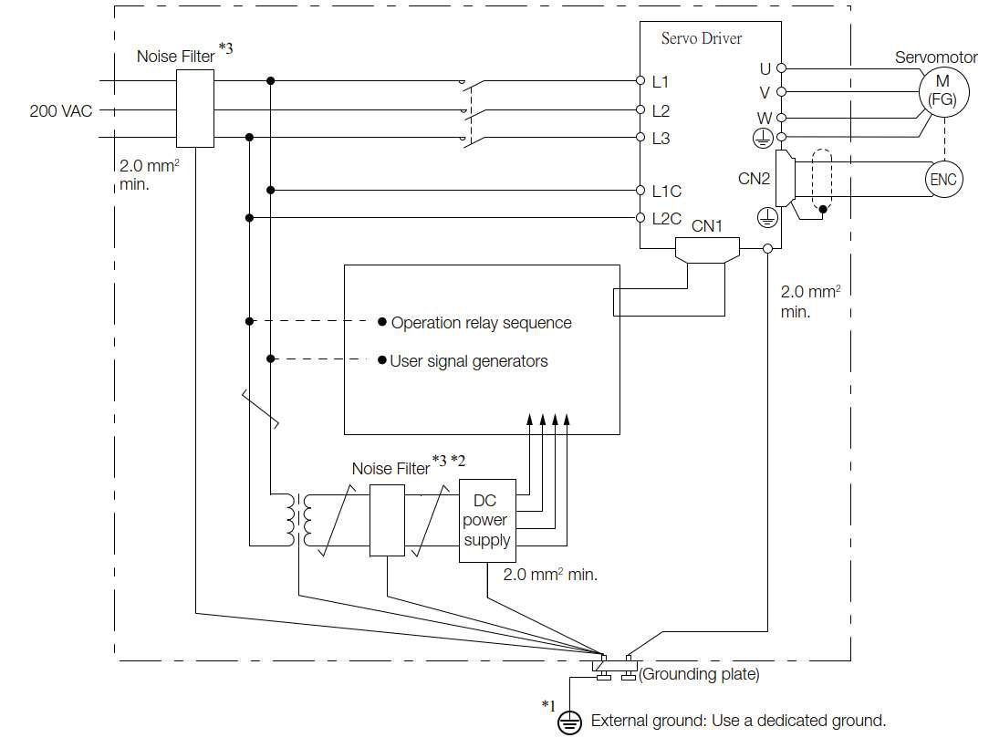
*1. For the ground wire, use a wire with a thickness of at least 2.0 mm2 (preferably, flat braided copper wire).
*2. Whenever possible, use twisted-pair wires to wire all connections marked with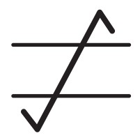
Noise Filter Wiring and Connection Precautions
Always observe the following precautions when wiring or connecting Noise Filters.
• Separate input lines from output lines. Do not place input lines and output lines in the same duct or bundle them
together.
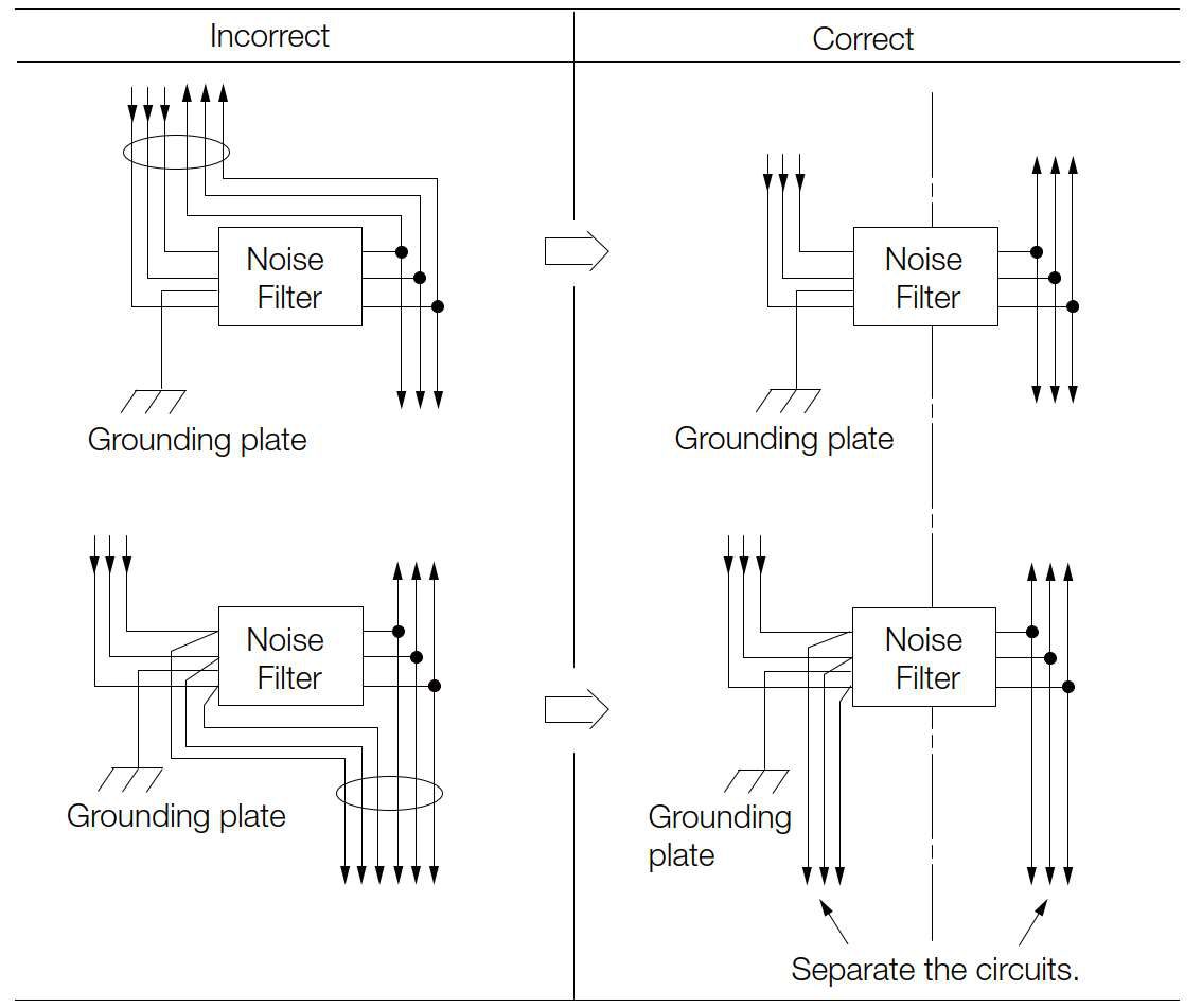
• Separate the Noise Filter ground wire from the output lines. Do not place the Noise Filter ground wire, output lines, and
other signal lines in the same duct or bundle them together.
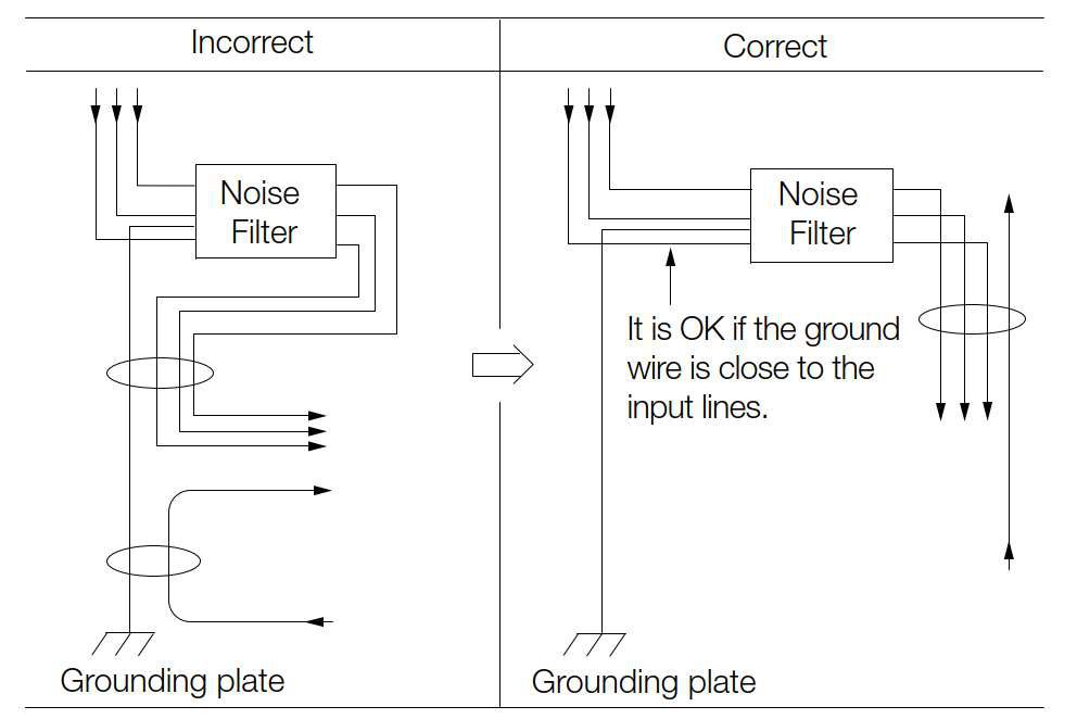
• Connect the Noise Filter ground wire directly to the grounding plate. Do not connect the Noise Filter ground wire to other ground wires.
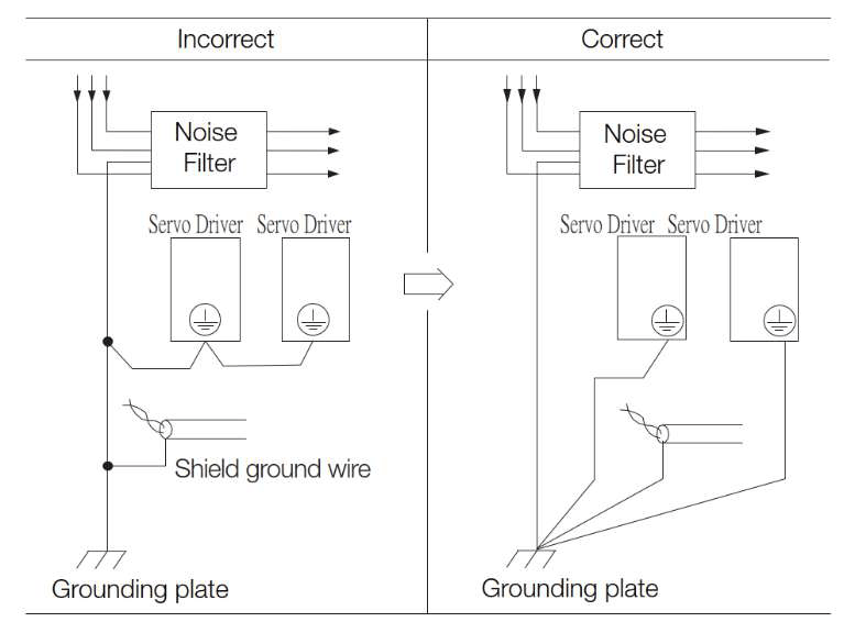
•If a Noise Filter is located inside a control panel, first connect the Noise Filter ground wire and the ground wires from other devices inside the control panel to the grounding plate for the control panel, then ground the plate.
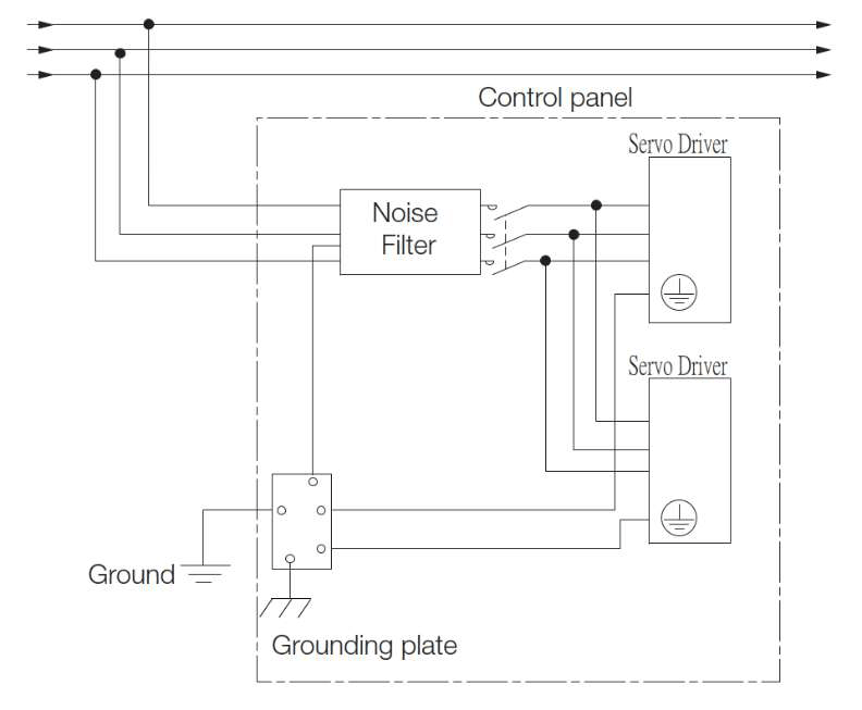
4.1.3 Grounding
Implement grounding measures as described in this section. Implementing suitable grounding measures will also help prevent malfunctions, which can be caused by noise.
Observe the following precautions when wiring the ground cable.
• Ground the servo driver to a resistance of 100 Ω or less.
• Be sure to ground at one point only.
• Ground the Servomotor directly if the Servomotor is insulated from the machine.
Motor Frame Ground or Motor Ground
If you ground the Servomotor through the machine, switching noise current can flow from the main circuit of the servo
driver through the stray capacitance of the Servomotor.To prevent this, always connect the FG terminal of the
Servomotor Main Circuit Cable connected to the Servomotor to the ground terminal on the servo driver. Also be sure to
ground the ground terminal. Always connect the shield wire of the Encoder Cable connected to the Servomotor to the
connector case (shell).
Ground both the Moving Coil and Magnetic Way of a Linear Servomotor
Noise on I/O Signal Cables
If noise enters the I/O Signal Cable, connect the shield of the I/O Signal Cable to the connector shell to ground it. If the Servomotor Main Circuit Cable is placed in a metal conduit, ground the conduit and its junction box. For all grounding, ground at one point only.
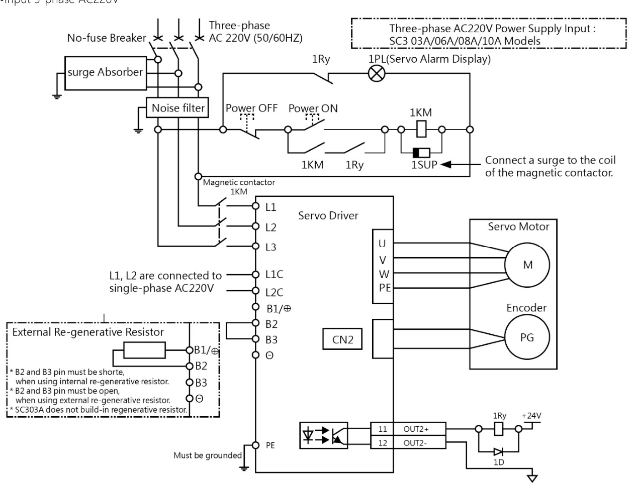
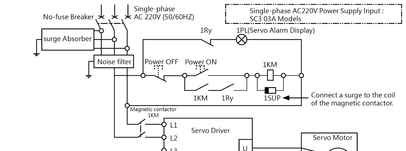
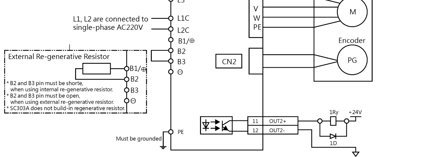
4.2 Basic Wiring Diagrams
• Input 3-phase AC380V
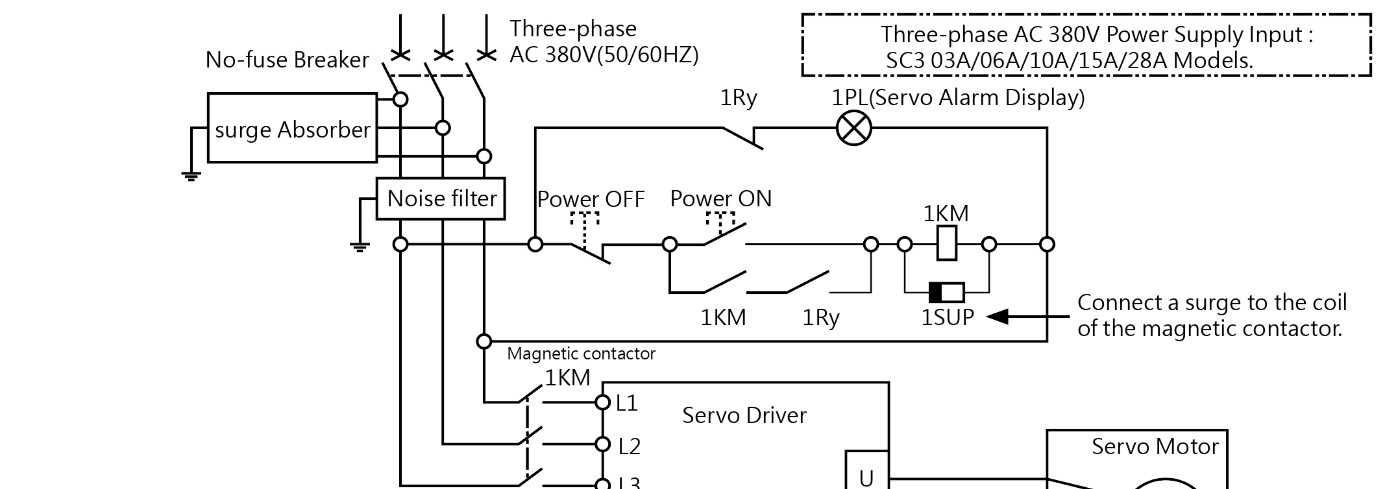
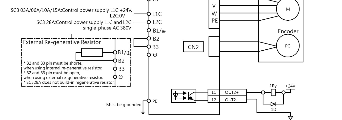
•Input 1-phase AC220V
4.3 Wiring the Power Supply to the servo driver
4.3.1 Terminal Symbols and Terminal Names
Use the main circuit connector on the servo driver to wire the main circuit power supply and control circuit power supply to the servo driver.
|
|
|
Wire all connections correctly according to the following table and specified reference information. There is a risk of servo driver failure or fire if incorrect wiring is performed. |
 CAUTION
The Servo driver have the following four types of main circuit power supply input specifica-tions.
|
■ |
1-phase/3-phaseAC220VPower Supply Input |
|
Terminal Symbols |
Terminal Name |
Specifications and Reference |
|
L1,L2,L3 |
Main circuit power |
3-phaseAC 200V~240V,-15%~+10%,50/60Hz 1-phaseAC 200V~240V,-15%~+10%,50/60Hz |
|
L1C、L2C |
Control power supply terminals |
1-phaseAC 200V~240V,-15%~+10%,50/60Hz |
|
B1/⊕、B2、B3 |
Regenerative Resistor terminals |
If the regenerative capacity is insufficient, connect an External Regenerative Resistor between B1/ and B2. The External Regenerative Resistor is not included. Obtain it separately. |
|
⊖ |
– |
None. (Do not connect anything to this terminal.) |
■ 3-phaseAC380V Power Supply input
|
Terminal Symbols |
Terminal Name |
Specifications and Reference |
|
L1,L2,L3 |
Main circuit power supply input |
3-phaseAC 380V~420V,-15%~+10%,50/60Hz |
|
L1C、L2C |
Control power |
03/06/10/15A: DC 24V ,-10%~+10%,50W |
|
B1/⊕、B2、B3 |
Regenerative |
03A/06A/10A/15A |
|
28A |
||
|
⊖ |
– |
None. (Do not connect anything to this terminal.) |
4.3.2 Wiring Procedure for Main Circuit Connector
• Required Items
|
Required Item |
Remarks |
|
Spring Opener or Flatblade |
●Spring Opener servo driver accessory |
|
● Flat-blade screwdriver |
1.Remove the main circuit connector and motor connector from the servo driver. 2.Remove the sheath from the wire to connect.
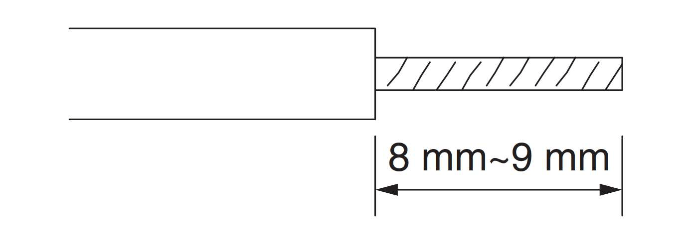
3.Open the wire insertion hole on the terminal connector with the tool. There are the following two ways to open the insertion hole. Use either method.
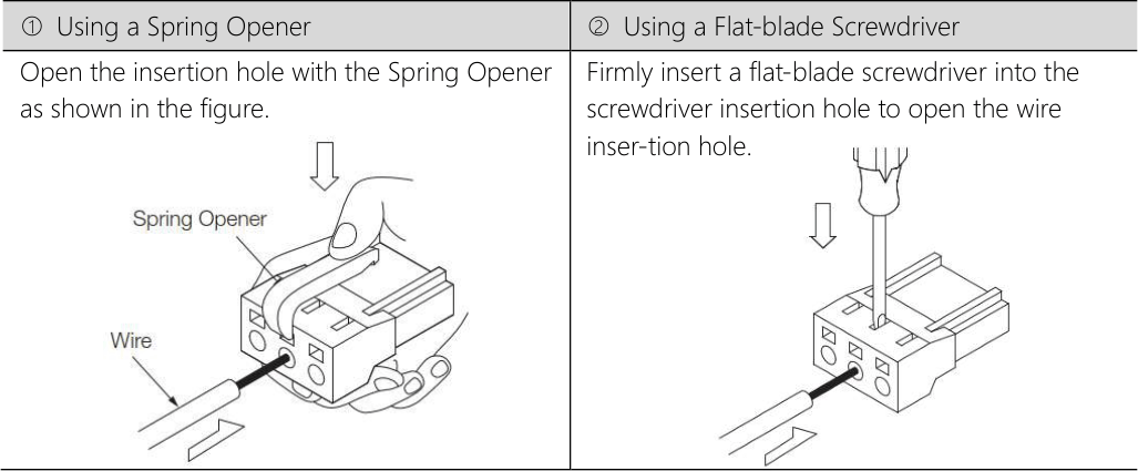
4.Insert the conductor into the wire insertion hole. Then, remove the Spring Opener or flat-blade screwdriver. 5.Make all other connections in the same way.
6.When you have completed wiring, attach the connectors to the servo driver.
4.3.3 Power ON Sequence
Consider the following points when you design the power ON sequence.
● The ALM (Servo Alarm) signal is output for up to five seconds when the control power supply is turned ON. Take this into consideration when you design the power ON sequence, and turn ON the main circuit power supply to the servo driver when the ALM signal is OFF (alarm cleared).
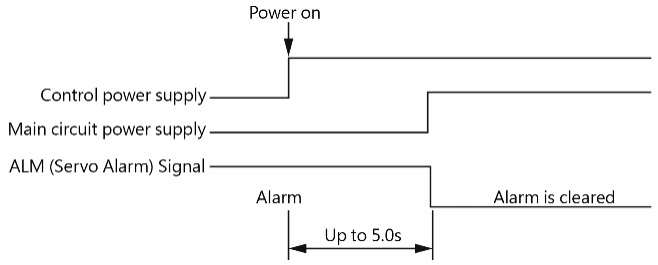
|
|
|
●Even after you turn OFF the power supply, a high residual voltage may still remain in the servo driver. To prevent electric shock, do not touch the power supply terminals after you turn OFF the power. When the voltage is discharged, the CHARGE indicator will turn OFF. Make sure the CHARGE indicator is OFF before you start wiring or inspection work. |
 WARNING
|
|
|
● Turn ON the control power supply before the main circuit power supply or turn ON the control power supply and the main circuit power supply at the same time.Turn OFF the main circuit power supply first, and then turn OFF the control power supply. |
 Important
4.3.4 Power Supply Wiring Diagrams ●Wiring Example for Three-Phase Power Supply Input
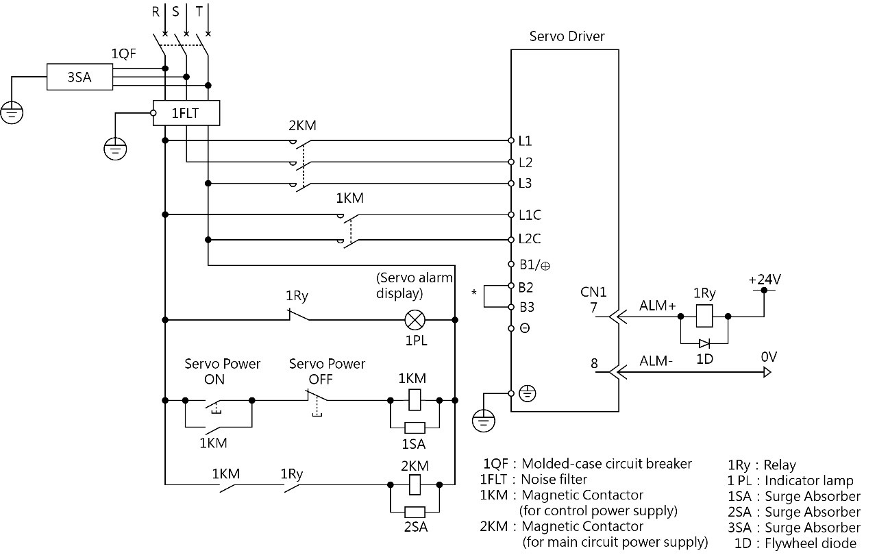
*You do not have to connect B2 and B3 for the following models: 03A and 28A, Do not connect them.
* AC380V 03A/06A/10A/15A use DC +24V for control power supply
4.3.5 Wiring Regenerative Resistors
This section describes how to connect External Regenerative Resistors.
|
|
|
● Be sure to wire Regenerative Resistors correctly. Do not connect B1/⊕ and B2. Doing so may result in fire or damage to the Regenerative Resistor or servo driver. |
 WARNING
Connecting Regenerative Resistors
1.Remove the lead from between the B2 and B3 terminals on the servo driver.
2.Connect the External Regenerative Resistor between the B1/⊕ and B2 terminals.
3.Set Pn600 (Regenerative Resistor Capacity) and Pn603 (Regenerative Resistance).
NOTE: 03A and 28A does not have build-in re-generative resistor, thereforce short wire between B2 and B3 is not
allowed, and connect an external regenerative resistor between B1/⊕ and B2.
4.4 Wiring Servomotors
4.4.1 Terminal Symbols and Terminal Names
The servo driver terminals or connectors that are required to connect the servo driver to a Servomotor are given below.
|
Terminal/Connector Symbols |
Terminal/Connector Name |
|
U,V,W |
Servomotor terminals |
|
|
Ground terminal |
|
CN2 |
Encoder connector |

4.4.2 Pin Arrangement of Encoder Connector (CN2)
|
Pin No. |
Signal |
Function |
|
1 |
PG5V |
Encoder power supply +5 V |
|
2 |
PG0V |
Encoder power supply 0 V |
|
3 |
E+* |
Battery for absolute encoder (+) |
|
4 |
E-* |
Battery for absolute encoder (-) |
|
5 |
SD+ |
Serial data (+) |
|
6 |
SD- |
Serial data (-) |
|
Shell |
Shield |
— |
*No wiring is required for an incremental encoder.
4.4.3 Wiring the servo driver to the Encoder
When Using an Absolute Encoder If you use an absolute encoder, use an Encoder Cable with a JUSP-BA01-E Battery Case or install a battery on the host controller.
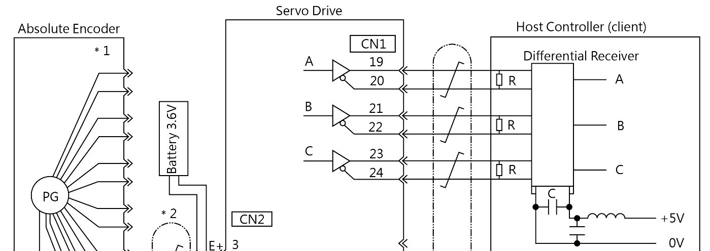
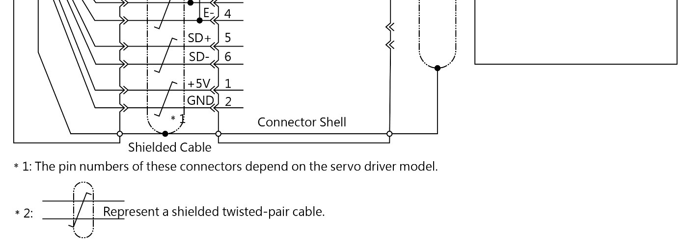
• Wiring Example When Using an Encoder Cable with a Battery Case
4.4.4 Wiring the servo driver to the Holding Brake
The Surge Absorber may affect the brake operation delay time. Configure the relay circuit to activate the holding brake for an emergency stop.
• The /BK (Brake) signal cannot be used with the default settings. You must allocate the output signal. Refer to the following section for details. • If you use a 24-V brake, install a separate power supply for the 24-VDC power supply from other power supplies, such as the one for the I/O signals of the CN1 connector. If the power supply is shared, the I/O signals may malfunction. |

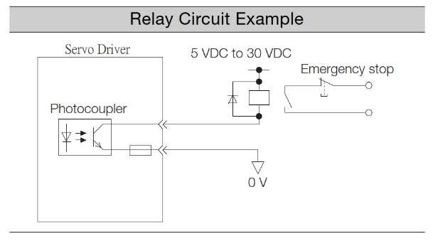
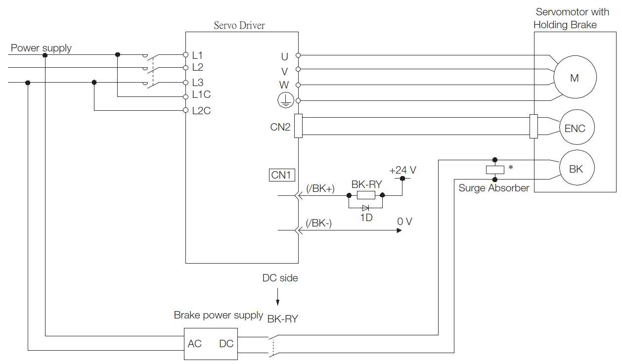
BK-RY: Brake control relay
1D:Fly wheeling Diode
4.5 I/O Signal Connections
4.5.1 I/O Signal Connector (CN1) Names and Functions
EtherCAT Type ( SC3 ▯▯▯▯▯ 00 ):
Default settings are given in parentheses.
|
Pin |
Name |
Function |
Pin |
Name |
Function |
|
1 |
— |
26 |
— |
||
|
2 |
— |
27 |
— |
||
|
3 |
— |
— |
28 |
— |
— |
|
4 |
— |
29 |
— |
||
|
5 |
— |
— |
30 |
— |
— |
|
6 |
— |
31 |
— |
||
|
7 |
OUT0+ |
Output 0, Reallocatable (Default:ALM) |
32 |
OUT3+ |
Output 3, Reallocatable (Factory reserved) |
|
8 |
OUT0- |
33 |
OUT3- |
||
|
9 |
OUT1+ |
Output 1, Reallocatable (Default:/BK) |
34 |
OUT4+ |
Output 4, Reallocatable (Factory reserved) |
|
10 |
OUT1- |
35 |
OUT4- |
||
|
11 |
OUT2+ |
Output 2, Reallocatable (Factory reserved) |
36 |
OUT5+ |
Output 5, Reallocatable (Factory reserved) |
|
12 |
OUT2- |
37 |
OUT5- |
||
|
13 |
DICOM |
input signal common terminal |
38 |
— |
|
|
14 |
IN0 |
Input 0, Reallocatable (Default:/P-OT) |
39 |
IN4 |
Input 4, Reallocatable (Factory reserved) |
|
15 |
IN1 |
Input 1, Reallocatable (Default:/N-OT) |
40 |
IN5 |
Input 5, Reallocatable (Factory reserved) |
|
16 |
IN2 |
Input 2, Reallocatable (Default:/DEC) |
41 |
IN6 |
Input 6, Reallocatable (Factory reserved) |
|
17 |
IN3 |
Input 3, Reallocatable (Factory reserved) |
42 |
IN7 |
Input 7, Reallocatable (Factory reserved) |
|
18 |
— |
43 |
— |
||
|
19 |
PAO+ |
PG Divided Pulse Output, Phase A |
44 |
— |
— |
|
20 |
PAO- |
45 |
— |
||
|
21 |
PBO+ |
PGDivided Pulse Output, Phase B |
46 |
— |
— |
|
22 |
PBO- |
47 |
— |
||
|
23 |
PCO+ |
PGDivided Pulse Output, Phase Z |
48 |
— |
— |
|
24 |
PCO- |
49 |
— |
||
|
25 |
GND |
Singal Ground |
50 |
GND |
Singal Ground |
NOTE: 1、The terminal displays "–", please do not use。
2、Please connect the input and output signals to the connector by shielded cables.
Pulses Type ( SC3 ▯▯▯▯▯ 10 ):
Default settings are given in parentheses
|
Pin NO. |
Name |
Function |
Pin NO. |
Name |
Function |
|
1 |
APULS+ |
Pulse Reference Input |
26 |
— |
— |
|
2 |
APULS- |
27 |
— |
||
|
3 |
BSIGN+ |
Sign of Reference Input (Line-Driver) |
28 |
— |
— |
|
4 |
BSIGN- |
29 |
— |
||
|
5 |
ANA0+ |
Speed Reference |
30 |
ANA1+ |
Torque Refer-ence Input |
|
6 |
ANA0- |
31 |
ANA1- |
||
|
7 |
OUT0+ |
Output 0,Reallocatable (Default:ALM) |
32 |
OUT3+ |
Output 3, Reallocatable (Factory reserved) |
|
8 |
OUT0- |
33 |
OUT3- |
||
|
9 |
OUT1+ |
Output 1,Reallocatable (Default:/COIN) |
34 |
OUT4+ |
Output 4, Reallocatable (Factory reserved) |
|
10 |
OUT1- |
35 |
OUT4- |
||
|
11 |
OUT2+ |
Output 2, Reallocatable (Default:/BK) |
36 |
OUT5+ |
Output 5, Reallocatable (Factory reserved) |
|
12 |
OUT2- |
37 |
OUT5- |
||
|
13 |
DICOM |
input signal common terminal |
38 |
— |
|
|
14 |
IN0 |
Input 0, Reallocatable (Default:/S-ON) |
39 |
IN4 |
Input 4, Reallocatable (Factory reserved) |
|
15 |
IN1 |
Input 1, Reallocatable (Default:/P-OT) |
40 |
IN5 |
Input 5, Reallocatable (Factory reserved) |
|
16 |
IN2 |
Input 2, Reallocatable (Default:/N-OT) |
41 |
IN6 |
Input 6, Reallocatable (Factory reserved) |
|
17 |
IN3 |
Input 3, Reallocatable (Default:/ALM-RST) |
42 |
IN7 |
Input 7, Reallocatable (Factory reserved) |
|
18 |
— |
43 |
— |
||
|
19 |
PAO+ |
PG Divided Pulse Output, Phase A |
44 |
— |
— |
|
20 |
PAO- |
45 |
— |
||
|
21 |
PBO+ |
PG Divided Pulse Output, Phase B |
46 |
— |
— |
|
22 |
PBO- |
47 |
— |
||
|
23 |
PCO+ |
PG Divided Pulse Output, Phase Z |
48 |
— |
— |
|
24 |
PCO- |
49 |
— |
||
|
25 |
GND |
Singal Ground |
50 |
GND |
Singal Ground |
NOTE: 1、The terminal displays "–", please do not use。
2、Please connect the input and output signals to the connector by shielded cables.
|
4.5.2 I/O Signal C EtherCAT Type ( SC3 ▯
|
onnector (CN1) Pin Arrangement ▯▯▯▯ 00 ):
|
||||||||||||||||||||||||||||||||||||||||||||||||||||||||||||||||||||||||||||||||||||||||||||||||||||||||||||
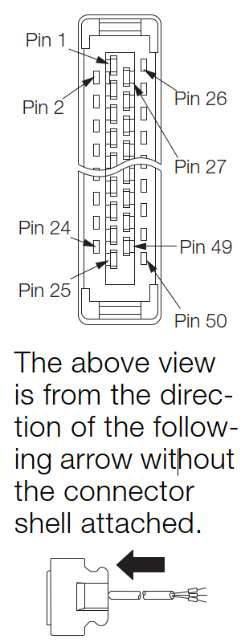
Pulses Type ( SC3 ▯▯▯▯▯ 10 ):
|
|
|
||||||||||||||||||||||||||||||||||||||||||||||||||||||||||||||||||||||||||||||||||||||||||||||||||||||||||||
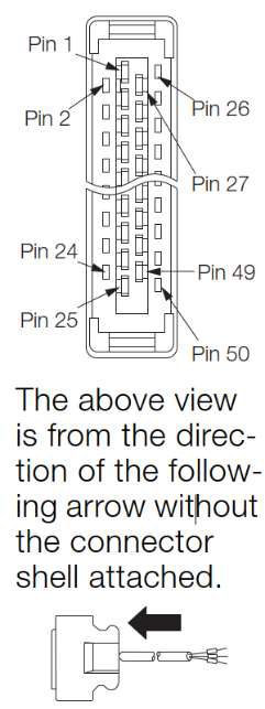
4.5.3 I/O Signal Wiring Examples
|
■ |
Communiaction Type:( SC3 ▯▯▯▯▯ 00 ):Postioning Control Mode |
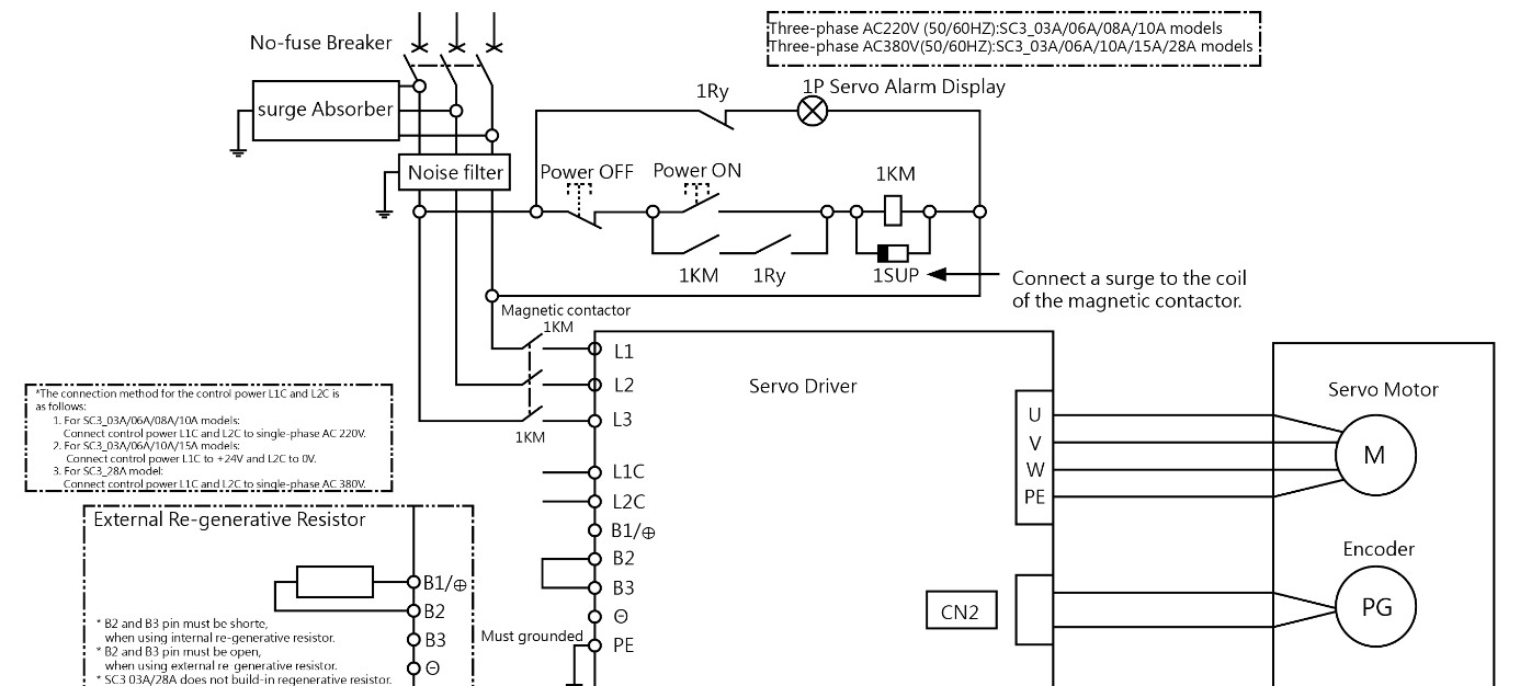
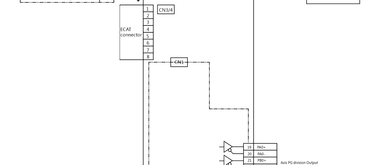
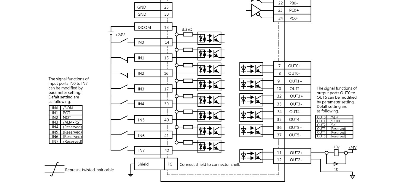
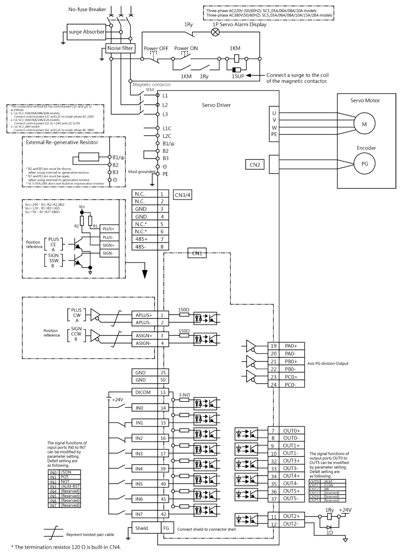
■ Pulses Type ( SC3 ▯▯▯▯▯ 10 ):Postioning Control Mode
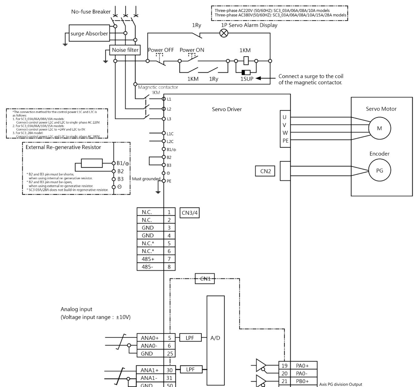
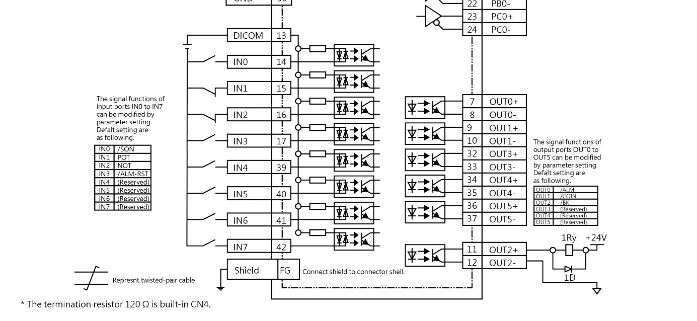
■ Pulses Type ( SC3 ▯▯▯▯▯ 10 ):Speed/Torque Contorl Mode
4.5.4 Sequence Input and Output Circuits
Sequence Input Circuits
◆ Photocoupler Input Circuits
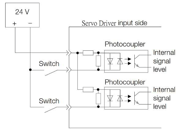
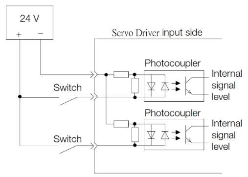
This section describes CN1 connector terminals CN1-IN0~CN1-IN7. The circuits are connected through relay or openollector transistor circuits. If you connect through a relay, use a low-current relay. If you do not use a low-current relay, a faulty contact may result.
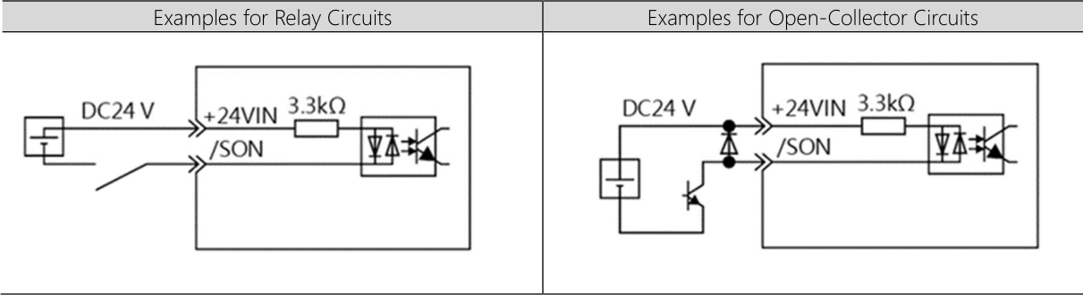
NOTE: The 24-VDC external power supply capacity must be 50 mA minimum.
The servo driver input circuits use bidirectional photocouplers. Select either a sink circuit or source circuit according to the specifications required by the machine.
Please choose either the common collector configuration or the common emitter configuration based on the mechanical specifications. (伺Servo Parameter Pn517~518)
|
Sink Circuits |
Source Circuits |
||
|
|
|
||
|
Input Signal Polarity |
Input Signal Polarity |
||
|
Photocoupler |
Internal Signal Leve |
Photocoupler |
Internal Signal Leve |
|
ON |
Low level |
ON |
High level |
|
OFF |
High level |
OFF |
Low level |
Sequence Output Circuit
|

◆ Open-Collector Output Circuits
The Alarm Code (ALO1, ALO2, and ALO3) signals are output from open-collector transistor output circuits. Connect an open-collector output circuit to a photocoupler, relay, or line-receiver circuit.
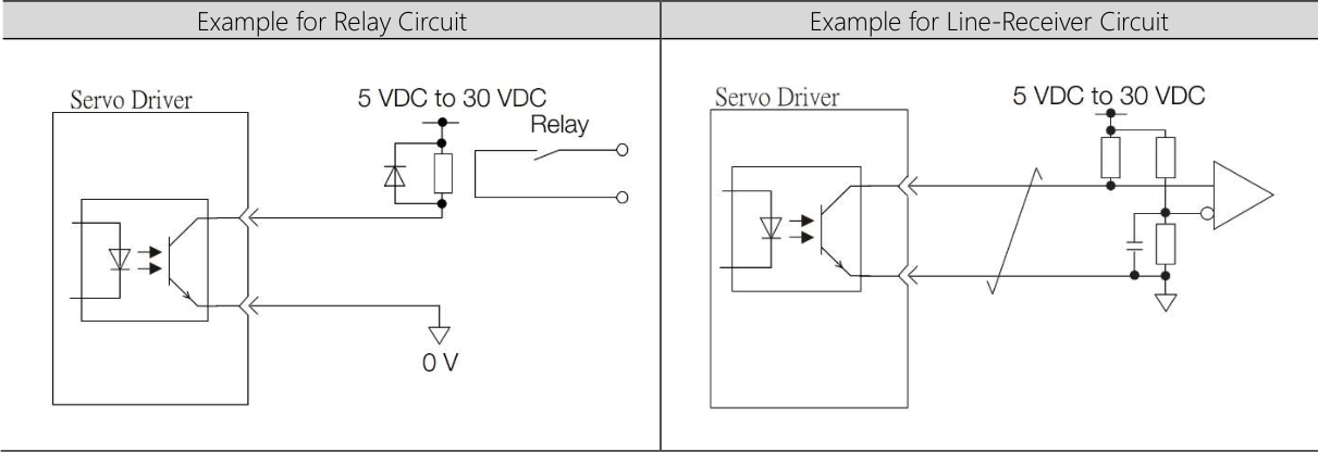
NOTE: The maximum allowable voltage and maximum allowable current for open-collector output circuits are as follows: • Maximum allowable voltage: 30 VDC
• Maximum allowable current: 20 mA DC
◆ Line-Driver Output Circuits
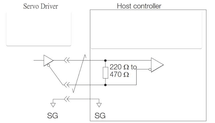
This section describes CN1-19~24 (Phase-A, B, Z Signal)
The serial data from the encoder is converted to two-phase (phases A and B) pulses. The resulting output signals (PAO, /PAO and PBO, /PBO), origin pulse signal (PCO and /PCO), and the absolute encoder position output signals (PSO and /PSO) are output with line-driver output circuits. Connect the line-driver output circuits to line-receiver circuits at the host controller.
Example for Line-Receiver Circuit
4.6 Encoder Connector Names
|
Pin No. |
1 |
2 |
3 |
4 |
5 |
6 |
|
Name |
5V |
GND |
E+ |
E- |
SD+ |
SD- |
NOTE:SD+、SD-are Pin of Data;E+、E-are Pin of Battery。
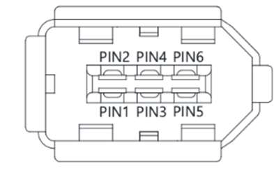
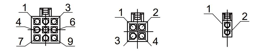
|
Encoder Cable Pins |
|||||||||
|
Num |
1 |
2 |
3 |
4 |
5 |
6 |
7 |
8 |
9 |
|
Def |
SD+ |
SD- |
E+ |
– |
– |
5V |
0V |
E- |
PE |
|
Power Cable Pins |
||||
|
Num |
1 |
2 |
3 |
4 |
|
Def |
U |
V |
W |
PE |
|
Brake Cable Pins |
||
|
Num |
1 |
2 |
|
Def |
24V |
0V |
|
Encoder |
Power |
Brake |
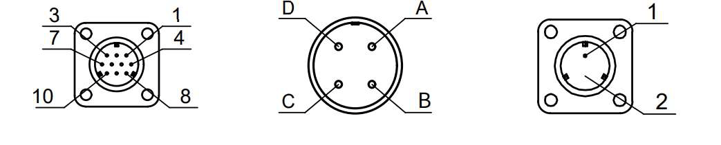
|
Encoder Cable Pins |
|||||||||
|
Num |
1 |
2 |
3 |
4 |
5 |
6 |
7 |
8 |
9 |
|
Def |
5V |
0V |
– |
E+ |
SD+ |
SD- |
– |
E- |
PE |
|
Power Cable Pins |
||||
|
Num |
A |
B |
C |
D |
|
Def |
U |
V |
W |
PE |
|
Brake Cable Pins |
||
|
Num |
1 |
2 |
|
Def |
24V |
0V |
|
Encoder |
Power |
Brake |
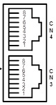
4.7 EtherCAT Connector Names
EtherCAT Type ( SC3 ▯▯▯▯▯ 00 ):
|
Pin Number |
1 |
2 |
3 |
4 |
5 |
6 |
7 |
8 |
|
|
Name |
CN3 |
TX_P_IN |
TX_N_IN |
RX_P_IN |
— |
— |
RX_N_IN |
— |
— |
|
CN4 |
TX_P_OUT |
TX_N_OUT |
RX_P_OUT |
— |
— |
RX_N_OUT |
— |
— |
|
Pulses Type ( SC3 ▯▯▯▯▯ 10 ):
|
Pin Number |
1 |
2 |
3 |
4 |
5 |
6 |
7 |
8 |
|
|
Name |
CN3 |
— |
— |
GND |
GND |
— |
— |
RS485+ |
RS485- |
|
CN4 |
— |
— |
GND |
GND |
Build-in 120Ω |
RS485+ |
RS485- |
||
Tip: press ← → to switch chapters, Ctrl+K to search