This chapter will introduce the various server functions provided by the HMI; users can use these server functions to achieve needs such as remote file access , send email and remote screen control.
4.1 【FTP Server】
FTP Server allows users to access files on the internal storage, SD card and USB storage device of the HMI. There are two ways to deploy the FTP server on the HMI. One is through the system settings of the HMI and the other is through the projects settings. Project settings will override system settings at project startup.
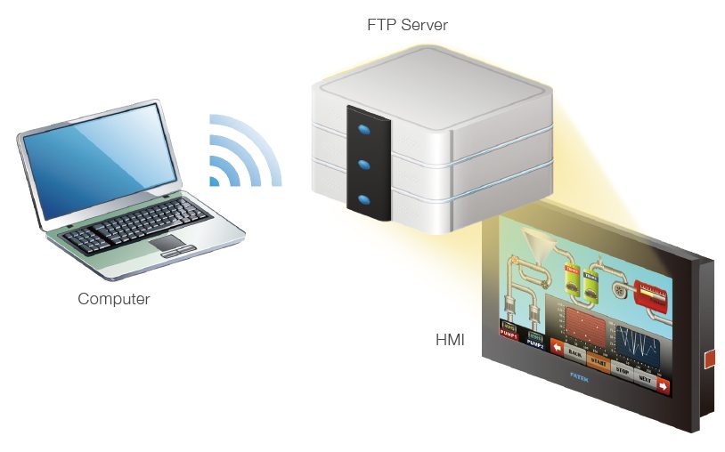
Figure 63 FTP Application Diagram
4.1.1 Deploying FTP Server using System Settings of HMI
The following screen will appear when the【Server Settings】page in the system settings of the HMI is opened:
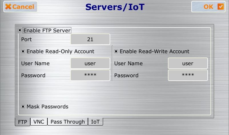
Figure 64 FTP Servers Setting–HMI
The following are the descriptions of each field in the figure above:
Table 31 FTP Server Settings
|
Field |
Description |
|
【Enable FTP Server】 |
Set to enable the FTP server; other fields can only be accessed when FTP Server is enabled. |
|
【Port】 |
Specify the port to listen for FTP Server; the default port is 21. |
|
【Enable Read-Only Account】 【User Name】 【Password】 |
Set to enable read-only accounts. A user name and password pair can be created once this option is enabled. Users who log in to FTP Server with this account can only read files and cannot perform operations including creating, modifying or deleting files. |
|
【Enable Read-Write Account】 【User Name】 【Password】 |
Set to enable read-write accounts. A user name and password pair can be created once this option is enabled. Users who log in to FTP Server with this account can access files as well as perform operations including creating, modifying or deleting files. |
|
【Mask Passwords】 |
Set if the password is to be encrypted. |
4.1.2 Deploying FTP Server using Project Settings
Click on【Server】in the【System】window of the【Project Explorer】to the left of FvDesigner to enter the【Server】settings screen where the【FTP】tab page can be used to setup FTP Server, as shown in the figure below:
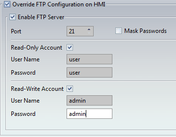
Figure 65 FTP Server Setting–Project
The FTP settings of the project can be used to override HMI【System Setting】FTP Server settings on the HMI when the project is loaded if【Overwrite FTP Configuration on HMI】is checked. The other settings are identical to the setting screen on the HMI; please refer to the explanations in Chapter 24.2.4-【Servers/IoT】.
Note: if HMI has enable FTP sever, but the project setting doesn’t enable FTP server, then the FTP sever will be disable when download the project.
4.1.3 FTP Server Example
We will use the following steps to illustrate how to use FTP Server:
- Enter the system settings of the HMI during boot up and then open【Server Settings】; setup FTP Server as shown in Figure 481.
- Use Windows Explorer to open the address:ftp://user:password@HMI IP Address to see the files on the HMI, as shown in the figure below:
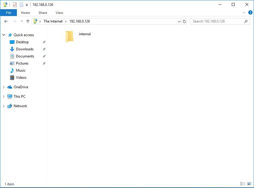
Figure 66 Using FTP to view files stored in internal memory, SD, or USB
4.2 【VNC Server】
VNC Server allows users to remotely view and operate the HMI functions through an Internet connection so that users can check the data on the HMI or operate the HMI remotely. There are two ways to deploy the VNC server on the HMI. One is through the system settings of the HMI and the other is through the project settings. Project settings will have a higher priority if both settings are set.
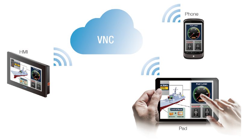
Figure 67 VNC application illustration
4.2.1 Deploying VNC Server using System Settings of HMI
The following screen will appear when the【Server Settings】page in the system settings interface of the HMI is opened:
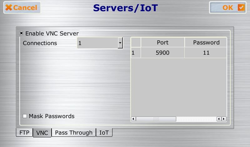
Figure 68 VNC Server Setting-HMI
The following are the descriptions of each field in the figure above:
Table 32 VNC Server Settings
|
Field |
Description |
|
【Enable VNC Server】 |
Set to enable the VNC server; other fields can only be set when the VNC server is enabled. |
|
【Connections】 |
Set how many VNC clients can be connected to this VNC server, the maximum number of support will vary depending on the model. |
|
【Mask Passwords】 |
Set if the password is to be encrypted. |
|
【Port】 |
Set the VNC port, can only set the first client port, the second will automatically increase, for example, the first set 5900, the second will be 5901. |
|
【Password】 |
The password used to login to the VNC server. |
4.2.2 Deploying VNC Server using Project Settings
Click on【Server】in the【System】window of the【Project Explorer】to the left of FvDesigner to enter the【Server】settings, in which the【VNC】tab page can be used to set the VNC server, as shown in the figure below:
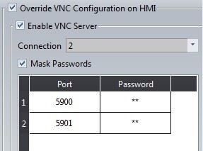
Figure 69 VNC Server Setting-Project
The VNC settings of the project can be used to override the VNC server settings when the project is loaded if【Overwrite VNC Configuration on HMI】is checked. The other settings are identical to the setting screen on the HMI; please refer to the explanations in Chapter 24.2.4 -【Servers/IoT】.
4.2.3 VNC Server Example
We will use the following steps to illustrate how to use the VNC server:
- Install a VNC client software; VNC Viewer 6.1.7(https://www.realvnc.com/download/viewer/) by RealVNC is used in this example.
- The following screen can be seen once VNC Viewer is opened and add link:
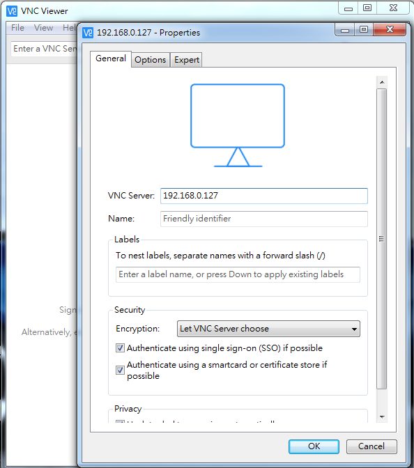
Figure 70 VNC Viewer Connection Screen
Press Connect after entering the IP of the HMI, and a prompt will appear asking the user to enter the password:
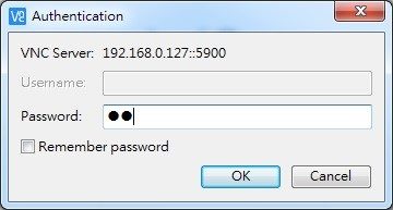
Figure 71 VNC Viewer Password Confirmation Screen
- Press OK after entering the password and real-time screens on the HMI can be seen.
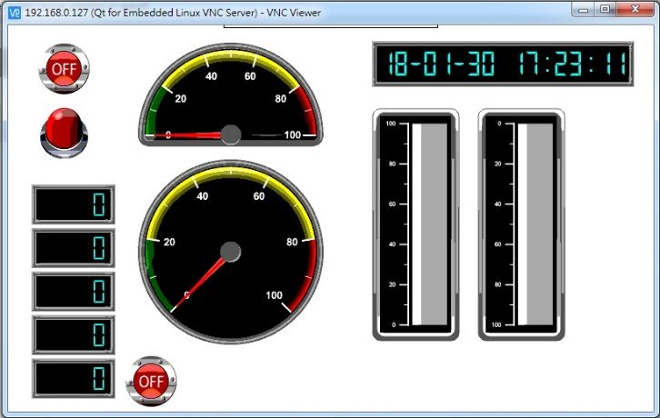
Figure 72 VNC Viewer remote monitor screen
Note: Please adjust the settings of the VNC Viewer if the HMI screens did not appear after entering the correct password; just set the value of FullColor in Options->Advanced->Expert to True.
4.3 【SMTP】
SMTP(Simple Mail Transfer Protocol), is a widely used protocol for sending mail over the Internet, this chapter will describe how to set to let user can send the email through HMI. For example, when an alarm occurs, an alarm message can be immediately sent to an operator or a designated e-mail recipient, so that the operator can handle and maintain the major issues that occur in the device.
4.3.1 【SMTP】setting
The function is on the left side of FvDesigner, is in【Project Explorer】【System】【Servers】setting page, figure as shown below.
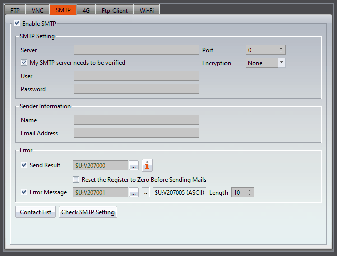
Figure 73【Sever】【SMTP】setting paging
Table 33【Sever】【SMTP】setting property
|
Field |
Description |
|||||||||||||||||||||||||||||||||||||||
|
【Enable SMTP】 |
Decide whether to enable SMTP function, check to set the following fields. |
|||||||||||||||||||||||||||||||||||||||
|
【SMTP Setting】 |
Set the server, port, user, encryption and password of【SMTP】 【Server】 The sending email server, the following table shows common mail servers for reference , please refer to the various mail server announcements .
Note: If using gmail server, users should set the 2-step verification and generate the app password. (Setting instruction: https://support.google.com/mail/answer/185833) 【Port】 Each e-mail mail server has different connection ports. Please refer to the above table or check the mail server announcements. 【Encryption】 Each email mail server has different encryption ways. Please refer to the above table or check the mail server announcements. 【My SMTP server needs to be verified】 If this function is checked, the user name and password should be entered, the actual usage depends on the connected server. 【User】 Email address of sender. 【Password】 Email password of sender. |
|||||||||||||||||||||||||||||||||||||||
|
【Sender Information】 |
【Name】 Set the name of the sender. 【Email Address】 Set the sender’s email address to send the email. |
|||||||||||||||||||||||||||||||||||||||
|
【Error】 |
Set whether to display the result of sending email on the HMI or PLC register, error code show as below.
【Reset the Register to Zero Before Sending Mails】 Check whether to reset the register to 0 before sending mails. 【Error Message】 Set the register to display error message from SMTP server with and the data type is【ASCII】. |
|||||||||||||||||||||||||||||||||||||||
|
【Contact List】 |
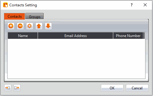
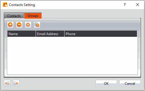
Set the recipients’s email address and groups, there are two pagings, includes【Contacts】and【Groups】. 【Contacts】paging shown as below, each meaning of the options are as follow:
The【Groups】tab page as shown below, the meaning of each setting option is as follows:
Note : the SMTP function of sending email will only send to the specified group. For example, group 1 has A recipient, group 2 has B and C recipients, when sending email to group 2, B and C will receive the same mail. |
|||||||||||||||||||||||||||||||||||||||
|
【Check SMTP Setting】 |
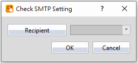
Check whether SMTP is setting correct or not, press【Check SMTP Setting】button, will show up the window and select the group.
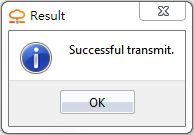
If success will show up the window below
And the group will receive a SMTP testing email from FvDesigner. |




4.3.2 【SMTP】setting example
We will use the following steps to explain how to set the【SMTP】function and test whether SMTP is correct, here we use gmail to explain.
Step1 : Fill in all all the blanks.
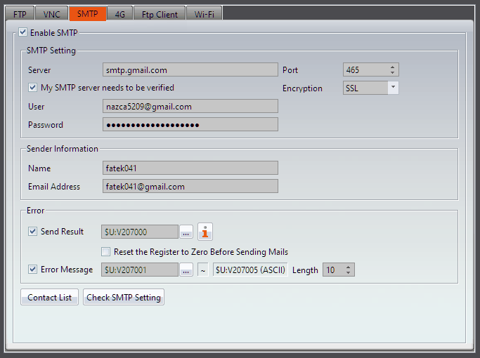
Figure 74 SMTP setting window
Step 2 : Click 【Contact List and enter】 【Contacts】 and 【Groups】.
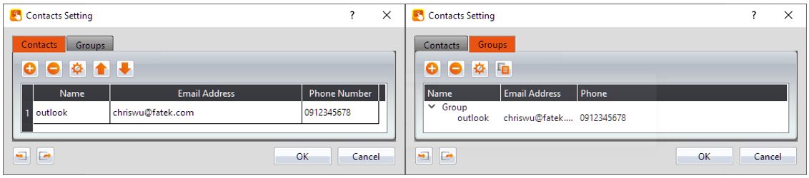
Figure 75 SMTP sender information setting window
Step 3 : Click 【Check SMTP setting】, select the group you want to test, and if the test is successful, a message will show Send Successful.
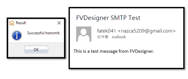
Figure 76 SMTP test successfully window
4.4 【4G】
Can plug 4G Dongle on HMI for wireless Internet access
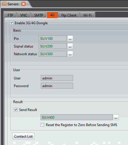
Figure 77【4G】setting page
Table 34【4G】properties setting
|
Property |
Description |
|
【Basic】 |
【Pin】 The pin code needs to be set up in the mobile phone or computer first, and the data type is【ASCII】, which occupies 6 words 【Signal status】 Display signal strength. The data type is【INT】, the range is 0~5 【Network status】 Show whether the network is connected or not, the data type is【INT】, the range is 0~1 |
|
【User】 |
This function is only useful when using Huawei’s dongle, and using other cards will not affect it. |
|
【Result】 |
【Send Result】 Display the SMS transmission result (can be set in the alarm), the data type is【INT】, -1 failure/1 success 【Reset the Register to Zero Before SMS】 Check whether to reset this address before sending SMS |
HMI can use 4G sim card for wireless Internet access, please notice that the HMI firmware version: 1.5.32 / OS version: OS 2.0.4 and above are only supported
No special settings are required to use the 4G network card to access the Internet. Just plug in the 4G Dongle before powering on the HMI.
HMI can use 4G sim card for wireless Internet access, please notice that the HMI firmware version: 1.6.69 and above are only supported
4.5 【FTP Client】
4.5.1 【FTP Client】setting
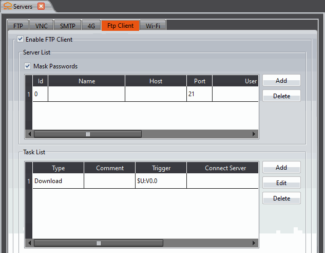
Figure 78【FTP Client】setting page
Table 35【FTP Client】properties setting
|
Property |
Description |
|
【Server List】 |
【Mask Passwords】 Set whether to show the password or not 【ID】 Set the server ID 【Name】 Set the server’s name 【Host】 Set the sever’s IP 【Port】 Set the server’s port. 【User】 Set the login name of the connection server 【Password】 Set the login password of the connection server |
|
【Task List】 |
【Type】 Display the task type 【Comment】 Display the comment of the task 【Trigger】 Display the triggered address 【Connect Server】 Display the connecting server of the task 【Number of Files】 Display the number of the transfer files. |
4.5.2 【FTP Client】Task setting
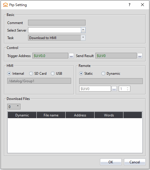
Figure 79【FTP Client】task list setting page
Table 36【FTP Client】task list properties setting
|
Property |
Description |
|
【Basic】 |
【Comment】 Comment for this task 【Select Server】 Select the server to connect 【Task】 Select the task, provides【Download to HMI】and【Upload to Server】 |
|
【Control】 |
【Trigger Address】 Set the trigger address to execute the task 【Send Result】 Display the result of the excuting task, the data type is【INT】, success: 1 / failed: -1 |
|
【HMI】 |
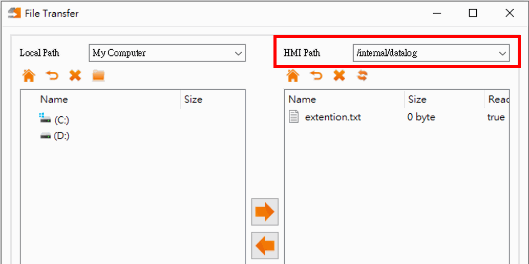
Select the location for uploading or downloading from the HMI. The following example: To use the data log folder as FTP
If you don’t know the internal location of the HMI, you can use【File Transfer】to connect and copy.
|
|
【Remote】 |
Set the data access location of the connection server. If it is not filled in, the root directory of the server will be used by default. 【Static】 Read the settings of the server itself, you can fill in the path in the field below 【Dynamic】 The data type is【ASCII】, you can fill in the path in the set register, for example: /HMI_Datalog |
|
【Download Files】 |
Set the number of access files for this task, the upper limit is 99 【Static】 Enter the full name of the file (including the extension filename) 【Dynamic】 The data type is【ASCII】, you can fill in the path in the set register, for example: DataLog.csv |
4.5.3 Example – Upload the data log to PC
The following is an example of using the FTP client function to upload DataLog to the PC.
(This is an example. To use the upload data log, refer to【Upload to remote】in chapter 0-
【Export Data】which will be easier)
- Set the connected server, please note that all parameters except the name must be the same as the server to be connected
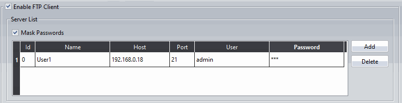
Figure 80 Set the server
- When setting up data log, please note that we are uploading files, so we must enable the export data function.
The location of storage is internal storage, and the name of the exported file is fixed as DataLog.
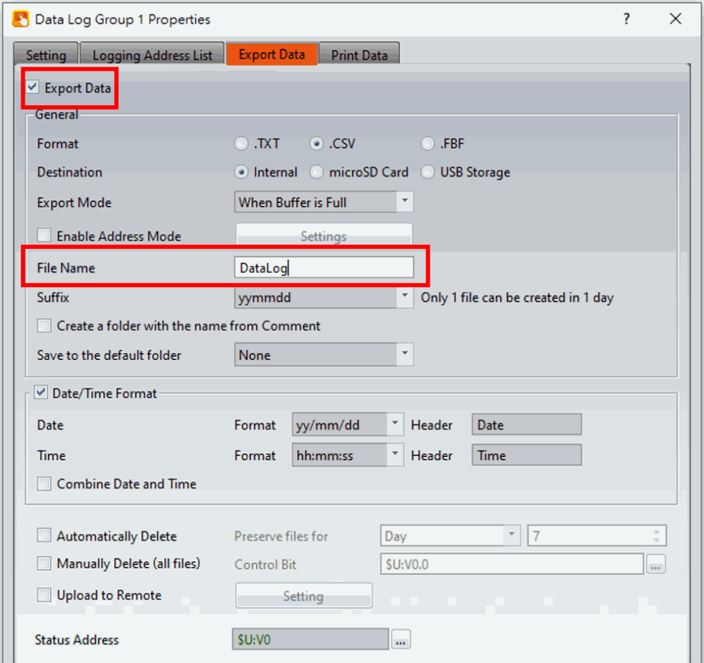
Figure 81 Data Log setting
- Set the task item, the example is uploading to the PC, the task should select upload to server, the location of data log and storage is set to internal storage, so check internal and fill in the path of the data log group in the field.
The file name must be the same as the exported file name
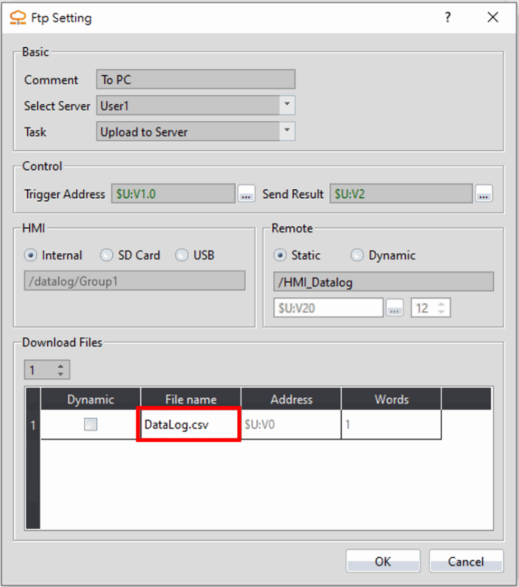
Figure 82 Ftp Setting
- Download the project to the HMI, trigger the task after exporting the file.
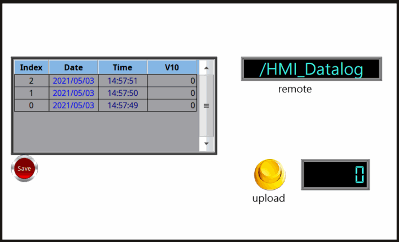
Figure 83 HMI execution screen
- After uploading, you can see the file on the PC. Please note that the FTP Server must be enabled on the computer, otherwise the above operations will not take effect.
For the FTP Server tool, there are many tools on the Internet, please check by yourself.
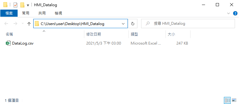
Figure 84 PC get the file
4.6 【Wi-Fi】
Wi-Fi Dongle can be plugged into the HMI for wireless Internet access.
Note: This is to enable the address control Wi-Fi function. Even if enable is not checked, the HMI can still plug in the Wi-Fi Dongle for wireless Internet access.
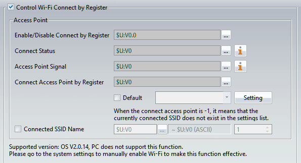
Figure 85【Wi-Fi】setting page
Table 37【Wi-Fi】properties setting page
|
Property |
Description |
||||||||||||||
|
【Enable/Disable Wi-Fi by Register】 |
Set a bit to control to enable or disable the Wi-Fi function |
||||||||||||||
|
【Connect Status】 |
Each status as the table, data type is【INT】
|
||||||||||||||
|
【Access Point Signal】 |
Each status as the table, data type is【INT】
|
||||||||||||||
|
【Connect Access Point by Register】 |
Select the access point number through the register, the data type is【INT】. 【Setting】: Access point can be set in advance.
|
||||||||||||||
|
【Connected SSID Name】 |
Set an address to display the name of the connected wireless network. |
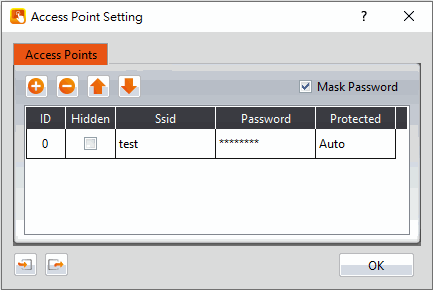
Please refer to ch 24.2.3.4-【Wi-Fi】for more details.
Tip: press ← → to switch chapters, Ctrl+K to search