9.1The Principle and the Structure of Interrupt Function
There are many jobs that FBs-PLC needs to carry out. For example, there are 20K words user’s program need to be solved, 512 points of I/O status need to be captured or updated, 5 communication ports need to be serviced, and etc. However, jobs can only be executed one at a time as there is merely one CPU available. Therefore, PLC service one job after another in sequence until all the jobs are executed once. Then, it will return to the first job to repeat the same cycle. The time interval of each execution is called the “scan time” of PLC. The CPU execution speed is extremely fast in comparison with human response. As far as human feeling is concerned, PLC almost completes all jobs at the same time when PLC can normally complete the foregoing huge workload within tens of milliseconds (ms). Hence, it can meet the requirements of the most practical control cases.
In most application cases, the control method described above is very much sufficient. But for some applications that require a high-speed response (such as positioning control), a delay in scan time will certainly mean an increase in error. Under the circumstances, only applying the “Interrupt” function can achieve the precision requirement.
The so-called “Interrupt” means the interrupt request to the CPU during normal scan cycle when an immediate response is required. After receiving such request, the CPU will promptly stop all scanning work to prioritize to perform and complete the corresponding service work before return (the so-called “Return from Interrupt” or RTI) to where interrupt occurred and resume the interrupted scanning work.
The service work needed to carry out while interrupt occurred is called Interrupt Service Routine, which is a subroutine consisted by a series of ladder codes. It is placed in the subroutine area and begin with the LBL instruction with reserved label name (please refer to Section 9.3). Since it is placed in the subroutine area, it will not be executed in a normal PLC scanning cycle (PLC only constantly scans the main program area but not the subroutine area).
In normal case, the CPU can promptly execute the corresponding interrupt routine within hundreds of micro-seconds when an interrupt occurred. When there are more than one interrupt occurred at the same time (e.g. FBs-PLC has 49 interrupts source), only the interrupt with highest priority can be executed. All the other interrupt routines need to wait until it became the highest priority among the pending interrupts. Consequently, a response delay of hundreds of microseconds, or even few milliseconds, may be caused. Hence, in a multiple interrupt inputs structure, an interrupt priority is given to each interrupt in accordance with its importance. In case another interrupt request is made when the PLC is carrying out the interrupt service routine for an interrupt request that has a higher priority than the new interrupt request, the CPU will wait until the execution of the subroutine is completed before accepting the new interrupt request. However, if the priority of the new interrupt request is higher than the one being executed, the CPU will stop the running of the current interrupt service routine immediately to execute the interrupt service routine with a higher priority. After completing the execution, the CPU will return to the previously interrupted service routine with a lower priority to continue the incomplete work. This kind of interrupt in an interrupt execution is called the “Nested Interrupt”. FBs-PLC can have up to 5 levels of nested interrupts. The diagram below shows the examples of single interrupts and nested interrupt:
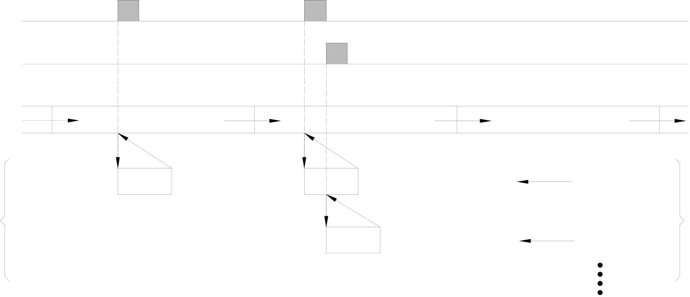
X8+interrupt
(Priorty:34)
HSC0 interrupt
(Priority:10)
|
Main |
Mian Program |
Mian Program |
Mian Program |
Nested Subroutine |
|
|
Program |
|||||
|
X8+I |
X8+I Subroutine |
First level |
|||
|
Subroutine |
|||||
|
can have up to 5 |
|||||
|
Subroutine |
HSC0I Subroutine |
Second level |
|||
|
level |
|||||
9.2Structure and Application of Interrupt Service Routine
Although both “Interrupt” and “Call” are having subroutines, but the calling methods (to jump to subroutine for execution) are different. When the CALL command [FUN67] is executed by “Call” in the main program, the CPU will execute the subroutine with the label name designated by the CALL command. The CPU will return to the main program after the RTS (Return from Subroutine) command is executed.
The calling of “Interrupt” is triggered by, instead of using software commands, the hardware interrupt signal to the CPU. The CPU will identify the source of the interrupt and jump automatically to the “Interrupt Service Routine” with the label name of the interrupt in the subroutine for execution. It will return to the main program after the RTI (Return from Interrupt) command is executed. Therefore, there is no ladder code relevant to interrupt in the main program area.
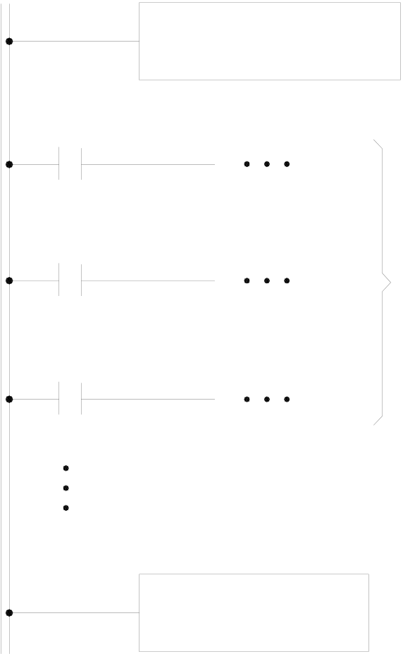
Interrupt label (Head)
As mentioned before, interrupt service routine
must be placed in the sub program area. The
structure is shown as the diagram on the right where
a “head”, a “tail” and the main body of the service
routine are included. The “head” is the “interrupt label name” of the interrupt (to be discussed in the next section). The “tail” is the RTI command [FUN69], to tell the CPU that the interrupt subroutine is ended and it should jump to the place where were interrupted, please refers to FUN69 (RTI) instruction. In between the “head” and the “tail” is the main body of the interrupt service routine used to tell the CPU what control actions should be executed when interrupt occurs.
 The power line for subroutine is indicated by
double lines to differentiate from the power line for
9.3Interrupt Source, Label and Priority for FBs-PLC
As described in the last section, every “Interrupt Service Routine” should have a unique “Interrupt Label”. There are 49 corresponding “Interrupt Labels” for interrupts, namely “Interrupt Reserve Words”, cab be used in the sub program area of FBs-PLC. These labels are dedicated to the interrupt routines hence cannot use for normal subroutine or jump target.
The “Interrupt Label” (Interrupt Reserve Words) are all suffix with an “I” letter. For examples, the interrupt label for high-speed counter HSC0 should be “HSC0I” and the interrupt label for X0+ should be “X0+I”. The “Interrupt Labels” and their priorities for the 49 FBs-PLC interrupt sources of FBs-PLC are shown as below.
The following table is the interrupt sources and their label names. To compatible with previous versions of programming tool, besides HSC/HST, the label names in old versions are also enlisted (label name with parenthesis).
The new label names are prefer than old while in usage (HSTAI, 1MSI~100MSI, X0+I~X15-I are prior in using).
(The priority of interrupt is inversely proportional to the value of priority)
|
Interrupt Source |
Priority |
Interrupt Label |
Condition for Interrupt |
Note |
|
High Speed Timer |
1 |
HSTAI (ATMRI) |
Timing from HSTA to(CV=PV) |
No interrupt when act as a cyclic timer |
|
Internal |
2 |
1MSI (1MS) |
One interrupt every 1mS |
One kind of time base interrupt is allowed at a time (please refer to Therefore, the actual |
|
3 |
2MSI (2MS) |
One interrupt every 2mS |
||
|
4 |
3MSI (3MS) |
One interrupt every 3mS |
||
|
5 |
4MSI (4MS) |
One interrupt every 4mS |
||
|
6 |
5MSI (5MS) |
One interrupt every 5mS |
||
|
7 |
10MSI (10MS) |
One interrupt every 10mS |
||
|
8 |
50MSI (50MS) |
One interrupt every 50mS |
||
|
9 |
100MSI (100MS) |
One interrupt every 100mS |
||
|
HSC |
10 |
HSC0I/HST0I |
Counting/Timing from HSC0/HST0 to (CV=PV) |
HSC0~HSC3 are labeled as HSC0I~HSC3I when configured as high speed counter; and are labeled as HST0I~HST3I for |
|
11 |
HSC1I/HST1I |
Counting/Timing from HSC1/HST1 to (CV=PV) |
||
|
12 |
HSC2I/HST2I |
Counting/Timing from HSC2/HST2 to (CV=PV) |
||
|
13 |
HSC3I/HST3I |
Counting/Timing from HSC3/HST3 to (CV=PV) |
||
|
PSO |
14 |
PSO0I |
Pulse output of PSO0 completed |
|
|
15 |
PSO1I |
Pulse output of PSO1 completed |
||
|
16 |
PSO2I |
Pulse output of PSO2 completed |
||
|
17 |
PSO3I |
Pulse output of PSO3 completed |
|
Interrupt Source |
Priority |
Interrupt Label |
Condition for Interrupt |
Note |
|
|
Interrupt from |
18 |
X0+I (INT0) |
↑ HSC4I ∫ HSC7I │ |
Interrupt when 0→1(•)of X0 |
The counter input and control input of the |
|
19 |
X0−I (INT0−) |
Interrupt when 1→0(•)of X0 |
|||
|
20 |
X1+I (INT1) |
Interrupt when 0→1(•)of X1 |
|||
|
21 |
X1−I (INT1−) |
Interrupt when 1→0(•)of X1 |
|||
|
22 |
X2+I (INT2) |
Interrupt when 0→1(•)of X2 |
|||
|
23 |
X2−I (INT2−) |
Interrupt when 1→0(•)of X2 |
|||
|
24 |
X3+I (INT3) |
Interrupt when 0→1(•)of X3 |
|||
|
25 |
X3−I (INT3−) |
Interrupt when 1→0(•)of X3 |
|||
|
26 |
X4+I (INT4) |
Interrupt when 0→1(•)of X4 |
|||
|
27 |
X4−I (INT4−) |
Interrupt when 1→0(•)of X4 |
|||
|
28 |
X5+I (INT5) |
Interrupt when 0→1(•)of X5 |
|||
|
29 |
X5−I (INT5−) |
Interrupt when 1→0(•)of X5 |
|||
|
30 |
X6+I (INT6) |
Interrupt when 0→1(•)of X6 |
|||
|
31 |
X6−I (INT6−) |
Interrupt when 1→0(•)of X6 |
|||
|
32 |
X7+I (INT7) |
Interrupt when 0→1(•)of X7 |
|||
|
33 |
X7−I (INT7−) |
Interrupt when 1→0(•)of X7 |
|||
|
34 |
X8+I (INT8) |
Interrupt when 0→1(•)of X8 |
|||
|
35 |
X8−I (INT8−) |
Interrupt when 1→0(•)of X8 |
|||
|
36 |
X9+I (INT9) |
Interrupt when 0→1(•)of X9 |
|||
|
37 |
X9−I (INT9−) |
Interrupt when 1→0(•)of X9 |
|||
|
38 |
X10+I (INT10) |
Interrupt when 0→1(•)of X10 |
|||
|
39 |
X10−I (INT10−) |
Interrupt when 1→0(•)of X10 |
|||
|
40 |
X11+I (INT11) |
Interrupt when 0→1(•)of X11 |
|||
|
41 |
X11−I (INT11−) |
Interrupt when 1→0(•)of X11 |
|||
|
42 |
X12+I (INT12) |
Interrupt when 0→1(•)of X12 |
|||
|
43 |
X12−I (INT12−) |
Interrupt when 1→0(•)of X12 |
|||
|
44 |
X13+I (INT13) |
Interrupt when 0→1(•)of X13 |
|||
|
45 |
X13−I (INT13−) |
Interrupt when 1→0(•)of X13 |
|||
|
46 |
X14+I (INT14) |
Interrupt when 0→1(•)of X14 |
|||
|
47 |
X14−I (INT14−) |
Interrupt when 1→0(•)of X14 |
|||
|
48 |
X15+I (INT15) |
Interrupt when 0→1(•)of X15 |
|||
|
49 |
X15−I (INT15−) |
Interrupt when 1→0(•)of X15 |
|||

9.4How to Use Interrupt of FBs-PLC
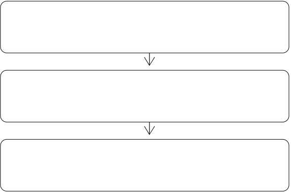
The applications of interrupt in internal timing, external input, HSC/HST or PSO are similar. Since the applications
of HSC/HST and PSO have been described in other chapters/sections, only examples of internal timing and external input
will be described in this section.
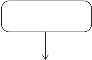
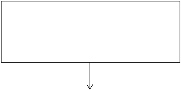
Begin
Setup interrupt configuration
Writing interrupt service routine in
sub program area
End
9.5Interrupt Configuration
————— Refer to section 9.5
————— Refer to section 9.6
In fact, interrupt configuration is simply to determine whether the application of a certain interrupt is to be used or not.
Interrupt configuration can be divided into configuration relevant to I/O or irrelevant to I/O two categories. HSTA, HSC/HST, PSO and external interrupt are all relevant to I/O and should be performed by the configuration function of programming tool, WinProladder or FP-08. The programming tool will automatically enable the interrupt of the device once it is configured.
The configuration of internal time base interrupt (1MSI~100MSI), which is irrelevant to I/O, need not to be configured. As long as the time base interrupt reserved words, which is placed in front of the interrupt service subroutine, appears in the sub program area, it imply the interrupt has been planned. If more than one such interrupts appear, can use low byte, B0~B7, of the special register R4162 to control the interrupt of 1MSI~100MSI to be executed or not.
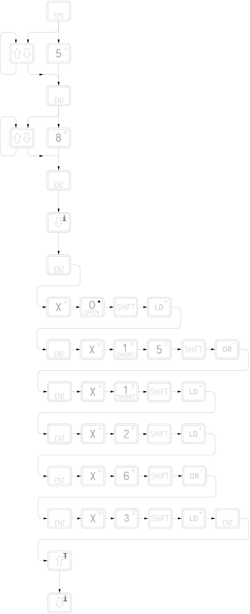
9.5.1Interrupt Configuration Through the Operation of FP-08
【Keypad Operation】【LCD Display】
•••••••••••••••
•
•••••••••••••••
•
••••••••••••••
••••••••••
•••••••••••••
•••••••••••
••••••••••••••
••••••••••••••
•••••••••••••••
••••••
•
••••••••
•
••••••••••••
••
••••••••••••
•••••
••••••••••••
••••••••
••••••••••••
•••••••••••
•••••••••
••
•••••••••••
•••••••••••
••••••••••
••
z External interrupt shares the 16 high-speed input points, X0~X15, with HSC and SPD instructions. Therefore, the number of the input points used by HSC or SPD cannot configure for external interrupt.
Note: SPD instruction can only uses X0~X7 8 input points for average speed detection.
z Once the interrupt configuration is determined, it cannot be changed in PLC RUN. But the EN command [FUN145] and DIS command [FUN146] provided by FBs-PLC can dynamically enable/disable the operation of interrupt of external, HSC and HSTA in PLC RUN. Please refer to the description of the two instructions.
|
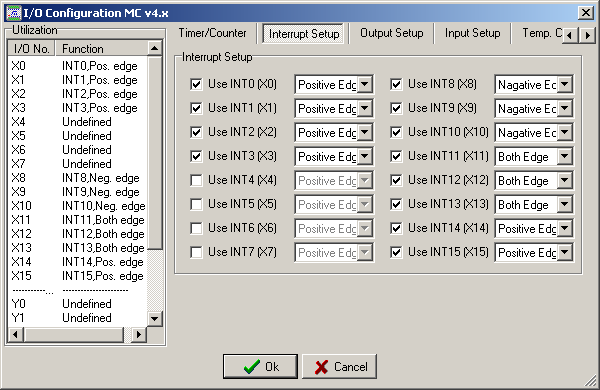
9.5.2 Interrupt Configuration Through the Operation of WinProladder |
Click the item “I/O Configuration” which in Project Windows :
|
Project name |
||||||
|
S |
stem Co |
nfigurat |
on |
|||
I/O Configuration Æ Select “Interrupt Setup”
When “Interrupt Setup” windows appear, then you can choose the Interrupt which you want.
9.5.3Internal Time Base Interrupt Configuration by R4162
When the internal time base interrupt reserved words (8 kinds, 1MSI~100MSI) appears in the sub program area, it imply that the designated interrupt has been planned and can be masked by using the 8 bits of the low byte in the register R4162 as shown in below:
|
R4162: |
B7 B6 B5 B4 B3 B2 B1 B0 ~
~ |
• When bit status =0: Enable the time base interrupt (not masked) • When bit status =1: Disable the time base interrupt (masked)
z Among B0~B7, if more than one of the bits is 0, FBs-PLC will enable the one with the smallest time base and disable the others. If the content of R4162 is 00H, then all time base interrupts will not be masked. However, if 1 MS and 2MS~100MS time base interrupt subroutine are all appeared in subprogram area, only the 1MS time base interrupt will be executed, and the others will not be executed.
z It is with great flexibility since the user can dynamically change the time base or pause or enable the interrupt by using the ladder program to change the value of R4162 at any time in PLC RUN.
z The default of R4162 is 0; it represents that 1MS~100MS time base interrupt are not been masked. As long as any one of time base interrupt processing subroutine exists in the sub program area, it will be executed periodically.
z Since a considerable CPU time is required for execution of every interrupt, the smaller the interrupt time base, the more interrupts required and the longer CPU time occupied. Therefore, application should be made only when necessary to avoid degradation of CPU performance.
9.6Examples of Interrupt Routine
|
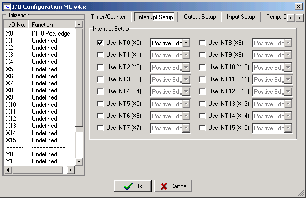
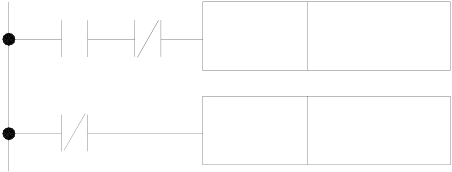
Example 1 Precision position control by positioning switch .(Configure X0 as the positive edge interrupt input) |
X0 : Position Sensor
X1 : Emergency Stop
Y0:Power motor



【Main program】
|
M0 |
X0 |
SET |
Y0 |
• M0 (start) changes from 0→1, the motor is ON. |
X1
RST Y0
【Subroutine】
|
65 |
X0+I |
• When the sensor, X0, detects the arriving of positioning |
|
LBL |
location, i.e. X0 change from 0 →1, the hardware will |
automatically execute the interrupt subroutine
|
69 |
EN |
RST |
Y0 |
• As motor Y0 changes to 0, it stops the motor immediately. |
|
EN |
74.IMDI0 |
• Output Y0 immediately to reduce delay caused by scan time |
||
|
D : |
Y0 |
|||
|
• It must employ immediate input/output instruction in the |
||||
|
N : |
1 |
interrupt subroutine to meet the real time high speed |
||
|
precision control requirement. |
||||
RTI
|
Example 2 1MS Internal Time base Interrupt |
【Main program】
|
M0 |
EN |
08.MOV |
• When M0=1, 1MS timing interrupt is disabled |
|
|
S : |
1 |
|||
|
(1MS timing interrupt being masked) |
||||
|
D : |
R4162 |
|||
|
M0 |
EN |
08.MOV |
• When M0=0, 1MS timing interrupt is enabled |
|
|
S : |
0 |
|||
|
D : |
R4162 |
|||
【Subroutine】
|
65 |
1MSI |
15 |
R0 |
OVF |
• After 1MS time base interrupt is started, the system will |
|
LBL |
|||||
|
EN |
automatically execute the interrupt subroutine every 1MS |
||||
|
(+1) |
• R0 is used as the up counting cyclic timer for every 1MS
|
69 |
EN |
16 |
R1 |
UDF |
time base |
|
(-1) |
|||||
|
• R1 is used as the down counting cyclic timer for every |
|||||
|
RTI |
1MS time base
|
9.7Capture Input and Digital Filter |
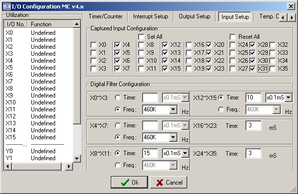
In many high-speed application, you can set interrupt input to prevent signal lose. Besides, you can set Captured
Input to capture the transient input signal less than one PLC scan time. The method to set Capture Input is very easy.
Click the item “I/O Configuration” which in Project Windows :
|
Project name |
||||||
|
S |
stem Co |
nfigurat |
on |
|||
I/O Configuration Æ Select “Input Setup”
When “Input Setup” windows appear, then you can choose the Capture Input point which you want.
|
Example_1 |
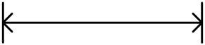
When the input is configured as the captured input and used for counting application, it is necessary that the input
signal period must be greater than 2 scan time for correct counting. For example the input frequency is 50Hz, then the
scan time of PLC must be less than 10mS for counting without loss.
Input signal < PLC scan time

PLC scan time PLC scan time









|
Example_2 |
The captured input can get the input signal which duration is less than 1 scan time of PLC.






The FBs series PLC main unit supports the captured input function as mentioned above, except this, it also supplies the digital filtering function for digital inputs X0~X35. There are 6 groups of digital inputs { (X0~X3)、(X4~X7)、(X8~X11)、(X12~X15)、(X16~X23)、(X24~X35) } for filtering setting.
There are 2 methods for digital filtering, one is the frequency domain, the other is the time domain. The filtering setting for upper four groups of digital inputs (X0~X15) can be either frequency domain or time domain; while in frequency domain, it supports the range of 14KHz~1.8MHz in total 8 selections; while in time domain, it supports the range of 1~15×1mS or 1~15×0.1mS selections. The last two groups of digital inputs (X16~X35) only supports the time domain, and the selections are 1~15×1mS.
Example 1
When the filtering time is 2mS, if the ON or OFF duration is less than 2mS, it will lose the ON or OFF signal.
|
|
|
|
|








|
Example 2 |
|
|
|
|
|
|
|
|









When the filtering frequency is 28KHz, if the input frequency is greater than 28KHz, it will lose the input signal.
|
|
|
|
|
|
|








Tip: press ← → to switch chapters, Ctrl+K to search