10.1FBs-PLC High-Speed Counter
The counting frequency of an ordinary PLC’s software counter can only reach tens of Hz (depending on the scan time). If the frequency of input signal is higher than that, it is necessary to utilize high-speed counter (HSC), otherwise loss count or even out of counting may occur. There are usually two types of HSC implemented for PLC. The hardware high-speed counter (HHSC) employed special hardware circuit and the software high-speed counter (SHSC) which when counting signal changes state will interrupt CPU to perform the increment/decrement counting operation. FBs-PLC provides up to 4 HHSCs (in SoC chips) and 4 SHSCs. All of them are all 32-bit high speed counter.
10.1.1Counting Modes of FBs-PLC High-Speed Counter
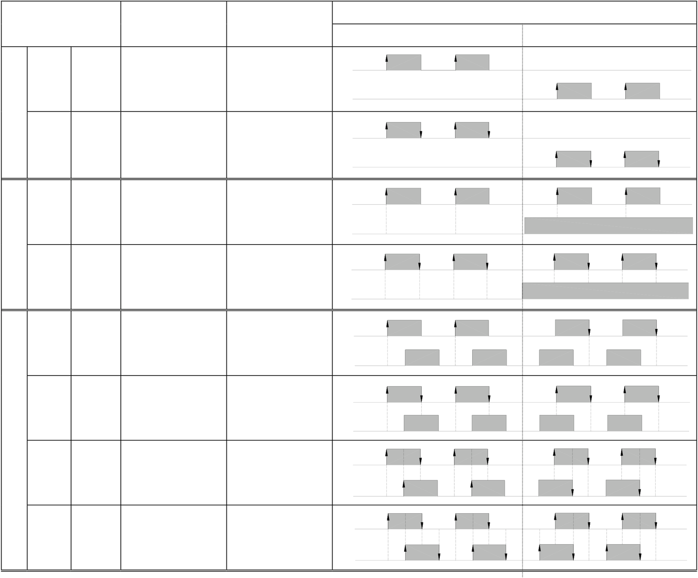
As shown in the table below, each of the four FBs-PLC HHSCs and SHSCs provides 8 and 3, respectively, kind of counting modes to choose from:
|
Counting Mode |
HHSC |
SHSC |
U |
Counting Waveform |
||
|
(HSC0~HSC3) |
(HSC4~HSC7) |
Up Counting(+1) |
Down Counting(−1) |
|||
|
Up-down pulse |
MD 0 U/D MD 1 U/D×2 |
○ |
○ |
|||
|
D |
||||||
|
○ |
U |
|||||
|
Pulse-direction |
MD 2 P/R MD 3 P/R×2 |
○ |
○ |
D |
||
|
P |
||||||
|
R |
||||||
|
○ |
P |
|||||
R
|
MD 4 A/B |
○ |
○ |
A |
B
|
AB phase |
MD 5 A/B×2 |
○ |
A |
|
MD 6 A/B×3 |
○ |
B |
|
|
A |
B
|
MD 7 A/B×4 |
○ |
A |
|
B |
• The up/down arrow (↑,↓) on the positive/negative edge in the waveform represents where counting (+1 or –1) occurs.
10.2 System Architecture of FBs-PLC High-Speed Counter
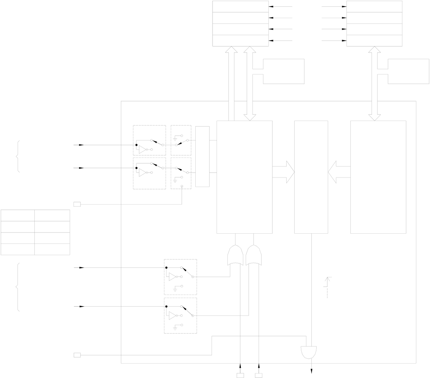
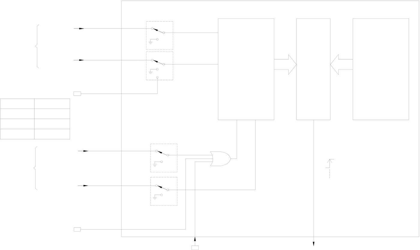
The diagrams below are the system architecture for FBs-PLC HHSC and SHSC where each one of them has multi-purpose input and counting functions. Some of the functions are built-in (such as CV register number, PV register number, interrupt label and relay number for software MASK, CLEAR and direction selection) that user need not to assign for configuration. However, some functions, with a “*” marked in the diagrams below, must use the programming tool to configure the HSC (such as HSC application selection, counting mode, application of each function input, inverse polarity and appointment of corresponding input point number Xn) etc. For detailed structure and operation of the 8 kind of counting modes that assigned in configuration, please refer to section 10.2.1~10.2.3 for explanation.
Note: CV (Current Value); PV (Preset Value).
|
z Use FUN92 to read out current counting value |
CV Register |
(HSC0) |
PV Register |
z Use FUN93 to write |
|
(CPU Intermal Memory) |
(CPU Internal Memory) |
|||
|
DR4096 |
DR4098 |
|||
|
from SoC chip hardware counter to put it into |
||||
|
DR4100 |
(HSC1) |
DR4102 |
PV register of |
|
|
CPU internal CV register. |
||||
|
DR4104 |
DR4106 |
hardware counter of |
||
|
(HSC2) |
||||
|
DR4108 |
DR4110 |
SoC chip. |
||
|
(HSC3) |
z Use FUN93 to write CV register content to SoC
|
chip. Resets and updates the CV of hardware |
FUN92 |
FUN93 |
FUN93 |
|
counter in SoC chip. |
|||
|
(HSCTR) |
(HSCTW) |
(HSCTW) |
(SoC Chip)
|
Counting |
(X0,X4,X8,X12)* |
U,P,A |
* |
* |
x1 |
CV |
PV |
|
x2 |
|||||||
|
(X1,X5,X9,X13)* |
D,R,B |
* |
* |
x3 |
|||
|
input |
|||||||
|
x4 |
Register |
Register |
Software direction selection
|
(HSC0) |
M1942 |
0:UP |
* |
M |
C |
|
|
1:DN |
||||||
|
(HSC1) |
M1948 |
|||||
|
(MD2,3 ONLY) |
||||||
|
(HSC2) |
M1978 |
|||||
|
(HSC3) |
M1981 |
|||||
|
Controlling |
(X2,X6,X10,X14)* |
M |
||||
|
Mask control |
||||||
input
|
(X3,X7,X11,X15)* |
C |
* |
PV=CV |
Clear control
EN(FUN145)/
DIS(FUN146)
|
(HSC0) |
Software |
Software |
TO CPU |
Interrupt Mask |
|
|
Mask |
Clear |
Interruput |
|||
|
M1940 |
M1941 |
(HSC0) |
HSC0I |
||
|
(HSC1) |
M1946 |
M1947 |
(HSC1) |
HSC1I |
|
|
(HSC2) |
M1976 |
M1977 |
(HSC2) |
HSC2I |
|
|
(HSC3) |
M1979 |
M1980 |
|||
|
(HSC3) |
HSC3I |
||||
System Architecture of HHSC(HSC0~HSC3)
(CPUInternal Memory)
|
Counting |
(X0~X15)* |
(U,P,A)* |
* |
CV Register |
PV Register |
(HSC4) |
|
DR4112(HSC4) |
DR4114(HSC4) |
|||||
|
or |
or |
|||||
|
input |
(X0~X15)* |
(D,R,B)* |
* |
DR4116(HSC5) |
DR4118(HSC5) |
|
|
or |
or |
|
||||
|
DR4120(HSC6) |
DR4122(HSC6) |
|||||
|
or |
or |
(HSC7) |
||||
|
DR4124(HSC7) |
DR4126(HSC7) |

Software direction selection
|
(HSC4) |
M1983 |
0:UP |
* |
M |
C |
PV=CV |
|
1:DN |
||||||
|
(HSC5) |
M1985 |
|||||
|
(MD2 ONLY) |
||||||
|
(HSC6) |
M1987 |
|||||
|
(HSC7) |
M1989 |
|||||
|
M |
||||||
|
(X0~X15)* |
||||||
|
Controlling |
(X0~X15)* |
Mask control |
* |
|||
|
input |
||||||
|
C |
Clear control
EN(FUN145)/
DIS(FUN146)
|
Software Mask |
Interrupt |
Interrupt Mask |
||||
|
(HSC4) |
M1982 |
|
||||
|
(HSC5) |
M1984 |
|||||
|
(HSC6) |
M1986 |
|||||
|
(HSC7) |
M1988 |
|||||
System Architecture of SHSC(HSC4~HSC7)
z All control signals of HHSC and SHSC are default as Active High (i.e. Status =1 for active and 0 for non-active). In order to cooperate with the sensor’s polarity, the HHSC counting inputs (U, D, P, R, A and B) and control inputs (M and C) can be selected for polarity inverse.
z By default when the MASK control signal, M is 1, the HSC counting pulse will be masked without any counting being performed and all HSC internal status (such as CV and PV) will remain unchanged. The HSC will function normally only when M returns to “0”. Some sensors have Enable outputs which function is on the contrary to MASK. Counters will not count when Enable = 0 and can only start functioning when Enable = 1. Then, function of inverse polarity input of MASK can be selected to cooperate with the sensors having Enable output.
z When the CLEAR control signal, C is 1, the HSC internal CV register will be cleared to 0 and no counting will be performed. The HSC will start counting from 0 when C returns to 0. Ladder program can also directly clear the CV register (DR4112, DR4116, DR4120, and DR4124), so as to clear the current counting value to 0.
z The four sets of FBs-PLC HHSC are located in the SoC chips where the CV or the PV registers the user can’t access directly. What the user can access are the CV registers (DR4096~DR4110) located in the CPU internal memory. Ideally, the contents of CV and PV registers in the chips should be updated simultaneously with the CV and PV registers in the CPU internal memory. However, to keep the correspondence between the two must be loaded or read by the CPU when they, in fact, belong to two different hardware circuits. It is necessary to use FUN93 to load the CV and the PV registers inside the CPU to the respective CV and PV registers (to allow HHSC to start counting from this initial value. Then, FUN92 can be used to read back the counting value of the HHSC CV register in the chips to the CV register in the CPU (i.e. the CV register in the CPU has the bi-direction function). Since read can only be carried out when FUN92 is executed (so-called “sampling” reading), it might result in difference between the HHSC CV value in the chips and the CV value in the CPU, the deviation will getting greater especially when the counting frequency is high.
z When the counting frequency is not high or the demand for positioning precision is not so much, using FUN92 in the main program to read the current counting value and then incorporate comparator instruction is adequate for a simple counting positioning control.
z When the demand for positioning precision is higher, or in the multi-zone count setting control, it may use the FUN92 to read the current counting value while in the time base interrupt routine and incorporate compare instruction to perform more precise counting positioning control.
z As the demand for positioning precision is extremely high, it must use the preset interrupt function of hardware counter. The preset value can load by FUN93 into the PV register of HHSC in the chipset. When CV value of HHSC reaches this preset value, the hardware comparator in the HHSC will send interrupt to CPU at the very moment CV=PV, and jump to interrupt subroutine to do real time control or procession.
z SHSC, on the other hand, uses the interrupt method to request an interrupt signal to the CPU when the counting input is on the rising edge. Then, the CPU will determine whether it should decrease or increase the internal CV register (since the CV register itself in the CPU is a SHSC CV register, no FUN92 or FUN93 is required). Each time when CV is updated, if the CPU find that it is equal to the PV register value, the CPU will jump immediately to the corresponding SHSC interrupt service routine for processing. Whenever there has a change in SHSC counting or control input can cause the CPU to be interrupted. The higher the counting frequency, the more of CPU time will be occupied. The CPU responding time will be considerably increased or even Watchdog time-out will be caused to force the PLC to stop operating. Therefore, it is preferred to use HHSC first; if it needs to use SHSC, the sum of all FBs-PLC SHSC input frequencies should not exceed 5KHz.
z None of the special relay controls, such as software MASK, CLEAR and direction control, is real time. This means that although MASK, CLEAR or direction change has been set during routine scanning, the signal will only be transmitted to HSC when I/O updating is under way after the completion of routine scanning. Hence, it is not suitable for the real time control in HSC operation (which should be mainly used for initial setting before HSC operation). Should real time control be required, please use hardware to control input or apply the FUN145(EN), FUN146(DIS), FUN92(HSCTR), and FUN93(HSCTW) etc. instructions for control.
z Every HSC is equipped with the functions, ENable(FUN145) and DISable(FUN146), when SHSC is disabled, it will stop counting and without the interrupt function ; when HHSC is disabled, the counting still works but the interrupt function being disabled.
10.2.1 The Up/Down Pulse Input Mode of High-Speed Counter (MD0,MD1)
The up/down pulse input of high-speed counter has up counting pulse input (U) and down counting pulse input (D)
that are independent to each other without any phase relationship. Each of them will +1 (U) or –1 (D) on the CV value
when the rising edge of the pulse input occurs (both positive and negative edge for MD1). This also applies when the
rising (or falling) edge of the U and D pulse occur simultaneously (it will offset with each other). Both of the two modes
have the built-in software MASK and CLEAR (CLEAR is not available for SHSC) control functions, when the control
function are not in use should keep the status (such as M1940 and M1941) as “0”. Apart from the built-in software
MASK and CLEAR, the controls of hardware MASK and CLEAR can also be configured. The MASK control is first
performed by the OR operation of the hardware and software control, then the result is send to the HSC MASK control M,
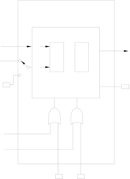
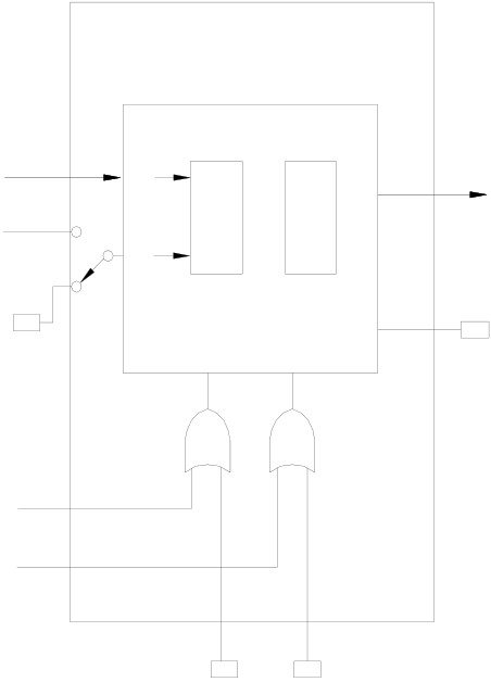
and so does CLEAR. Taking HSC0 as an example, the function schematic diagrams for MD0 and MD1 configured
separately are shown as below.
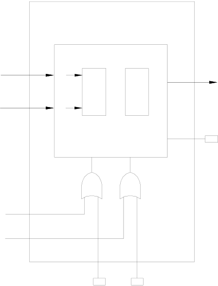
|
HSC0 |
HSC0I |
HSC0 |
||||||||
|
Up pulse X0 |
U |
CV |
PV |
Up pulse X0 |
U |
CV |
PV |
HSC0I |
||
|
Down pulse X1 |
D |
x1 |
Interrupt |
Down pulse X1 |
D |
x2 |
Interrupt |
|||
|
EN(FUN145)/ |
M |
EN/DIS |
EN(FUN145)/ |
|||||||
|
EN/DIS |
||||||||||
|
M |
C |
DIS(FUN146) |
C |
DIS(FUN146) |
||||||
|
Hardware mask X2 |
Software clear |
Hardware mask X2 |
||||||||
|
Hardware clear X3 |
Hardware clear X3 |
|||||||||
|
Software mask |
M1940M1941 |
Software mask |
M1940M1941 |
Software clear |
||||||
|
MD0(U/D) |
MD1(U/D×2)(HHSC Only) |
|||||||||
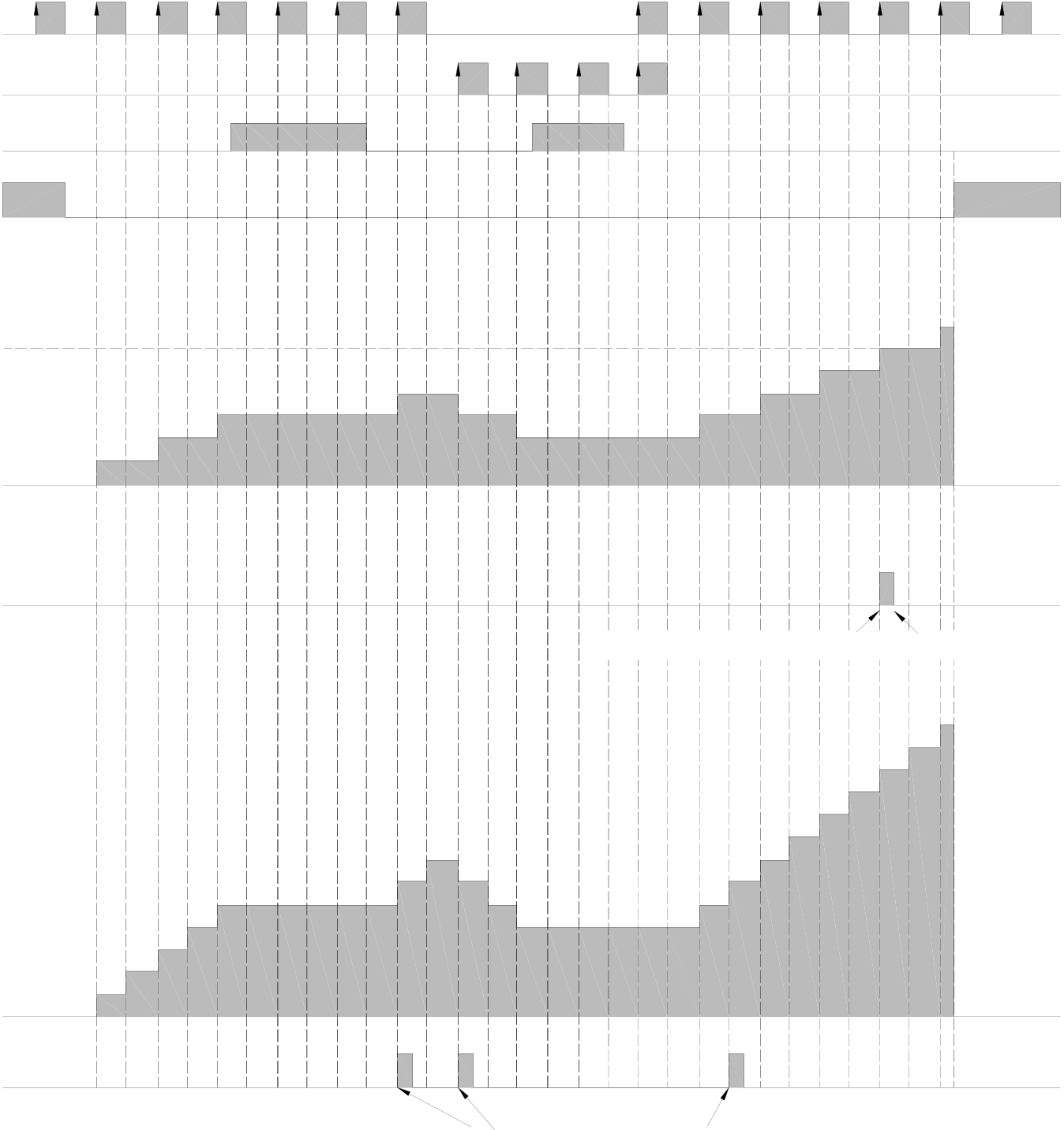
The Waveforms of the HSC, which is configured as up/down pulse input mode, and PV value is preset to 6:
X0(U)
X1(D)
M1940 or X2 (M)
M1941 or X3 (C)
|
MD0 |
|
PV=6 |
0 |
1 |
2 |
3 |
4 |
3 |
2 |
3 |
4 |
5 |
6 |
0 |
|
CV (x1) |
||||||||||||||
|
HSC0I |

HSC0 sends interrupt to CPUCPU receives and handles this interrupt
|
1 |
2 |
3 |
4 |
5 |
6 |
7 |
6 |
5 |
4 |
5 |
6 |
7 |
8 |
9 |
10 |
11 |
12 |
CV (x2)
MD1
HSC0I
HSC0 sends interrupt to CPU
10.2.2 Pulse/Direction Input Mode of High-Speed Counter (MD2, MD3)
The pulse-direction input mode high-speed counter only has one counting pulse input P (pulse). It requires another direction input R (Direction) to decide whether the CV value should +1 (R=0) or –1 (R=1) when the rising edge (both rising and falling edges for MD3) of counting pulse arrives. The same applies to counting of MD2 and MD3 except that MD2 only counts on the rising edge (+1 or –1) and MD3 counts on both rising and falling edges of PS pulse (twice the counts of MD2). These two modes have built-in software MASK, software CLEAR (SHSC does not have clear). When control function is not in use, it must keep the status (such as M1946 and M1947 in this example) to be 0. Apart from the built-in software MASK and CLEAR, the controls of hardware MASK and CLEAR can also be configured. The MASK control is first performed by the OR operation of the hardware and software control, then the result is send to the HSC MASK control M, and so does CLEAR. The function schematic diagrams of HSC1 configured individually for MD2 and MD3 are shown as below.
HSC1 HSC1
|
Pulse input X4 |
P |
CV |
PV |
HSC1I |
Pulse input X4 |
P |
CV |
PV |
HSC1I |
|||
|
Direction selecrion X5 |
R |
x1 |
Interrupt |
Direction selection X5 |
R |
x2 |
Interrupt |
|||||
|
Software direction |
M |
EN/DIS |
EN(FUN145)/ |
Software direction |
M1948 |
M |
EN/DIS |
EN(FUN145)/ |
||||
|
DIS(FUN146) |
selection |
C |
DIS(FUN146) |
|||||||||
|
C |
||||||||||||
|
Hardware mask X6 |
Hardware mask X6 |
|||||||||||
|
Software mask |
M1946M1947 |
Software clear |
Software mask |
M1946M1947 |
Software clear |
|||||||
|
MD2(P/R) |
MD3(P/R×2)(HHSC Only) |
|||||||||||
Direction selection of MD2 and MD3 HHSC, for HSC or SHSC, can be come from the external inputs (such as X5 in
this example) or the special relay in CPU (such as M1948 in this example) to reduce the usage of external input points.
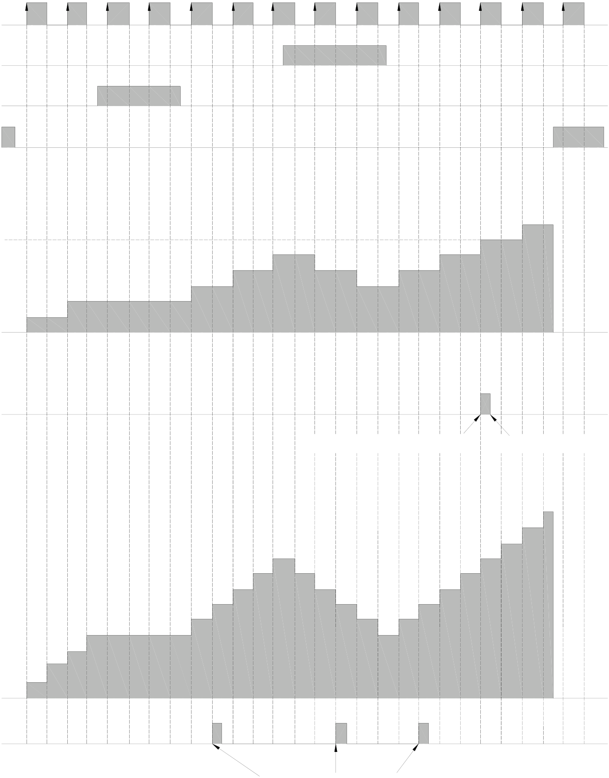
The diagram below is the waveform diagram for the relationship between counting and control of the two HSC. In this example the PV value is to 6.
X4(P)
X5(R)
X6(M)
X7(C)
|
MD2 |
|
PV=6 |
0 |
1 |
2 |
3 |
2 |
4 |
3 |
6 |
4 |
8 |
5 |
4 |
3 |
4 |
5 |
6 |
7 |
||||||
|
CV (x1) |
1 |
5 |
7 |
9 |
HSC1 sends interrupt to CPU |
CPU receives and handles this interrupt |
|||||||||||||||||||
|
HSC1I |
|||||||||||||||||||||||||
|
10 |
11 |
12 |
|||||||||||||||||||||||
|
8 |
7 |
6 |
5 |
4 |
5 |
6 |
7 |
8 |
|||||||||||||||||
|
9 |
|||||||||||||||||||||||||

CV (x2)
MD3
HSC1I
HSC1 sends interrupt to CPU
10.2.3AB Phase Input Mode of High-Speed Counter (MD4,MD5,MD6,MD7)
The AB phase high-speed counter is equipped with phase A and phase B pulse input with counting value +1 or –1, depending on the phase relationship between the two, i.e. the related counting of the two phases. If phase A is ahead of phase B, the CV value should be +1, else, the CV value should be –1. The counting of the four modes, MD4 (A/B), MD5 (A/B×2), MD6 (A/B×3) and MD7 (A/B×4), of AB phase HSC are similar. Their differences are:
cMD4 (A/B) : The rising edge of A is +1 when A is ahead of B and the falling edge of A is –1 when A is behind B.
dMD5 (A/B×2) : The rising and falling edges of A are +1 when A is ahead of B, and –1 when A is behind B (twice the counts of MD4).
eMD6 (A/B×3) : The rising and falling edges of A and rising edge of B are +1 when A is ahead of B. The rising and falling edges of A and the falling edge of B are –1 when A is behind B (three times the counts of MD4).
f MD7 (A/B×4) : The rising and falling edges of A and B are +1 when A is ahead of B and the rising and falling edges of A and B are –1 when A is behind B (four times the counts of MD4).
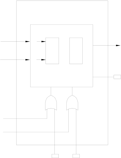
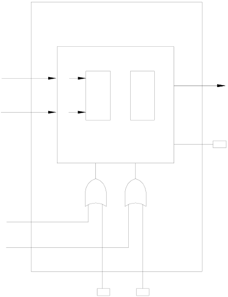
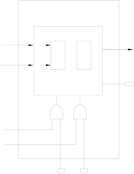
Other MD4~MD7 HSC modes also have built-in software MASK, software CLEAR (SHSC does not have clear). When control function is not in use, it must keep the status (such as M1946 and M1947 in this example) to be 0. Apart from the built-in software MASK and CLEAR, the controls of hardware MASK and CLEAR can also be configured. The MASK control is first performed by the OR operation of the hardware and software control, then the result is send to the HSC MASK control M, and so does CLEAR. The function schematic diagrams of HSC2 for the four MD4~MD7 HSC modes are shown as below.
HSC2 HSC2
|
A phase pulse X8 |
A |
CV |
PV |
HSC2I |
A phase pulse X8 |
A |
CV |
PV |
HSC2I |
||
|
B phase pulse X9 |
B |
x1 |
Interrupt |
B phase pulse X9 |
B |
x2 |
Interrupt |
||||
|
M |
EN/DIS |
EN(FUN145)/ |
M |
EN/DIS |
EN(FUN145)/ |
||||||
|
C |
DIS(FUN146) |
C |
DIS(FUN146) |
||||||||
|
Hardware mask X0 |
Hardware mask X0 |
||||||||||
|
Software mask |
M1976M1977 |
Hardware clear |
Software mask |
M1976M1977 |
Hardware clear |
||||||
|
MD4(A/B) HSC2 |
MD5(A/B×2)(HHSC Only) HSC2 |
||||||||||
|
A phase pulse X8 |
A |
CV |
PV |
HSC2I |
A phase pulse X8 |
A |
CV |
PV |
||||
|
x4 |
HSC2I |
|||||||||||
|
x3 |
B phase pulse X9 |
B |
||||||||||
|
Interrupt |
||||||||||||
|
B phase pulse X9 |
B |
|||||||||||
|
Hardware mask X10 |
M |
EN/DIS |
EN(FUN145)/ |
M |
EN/DIS |
EN(FUN145)/ |
||||||
|
C |
DIS(FUN146) |
C |
DIS(FUN146) |
|||||||||
|
Hardware mask X10 |
||||||||||||
|
Hardeare clear X11 |
Hardeare clear X11 |
M1976M1977 |
Hardware clear |
|||||||||
|
Software mask |
M1976M1977 |
Hardware clear |
Software mask |
|||||||||
MD6(A/B×3)(HHSC Only)
MD7(A/B×4)(HHSC Only)
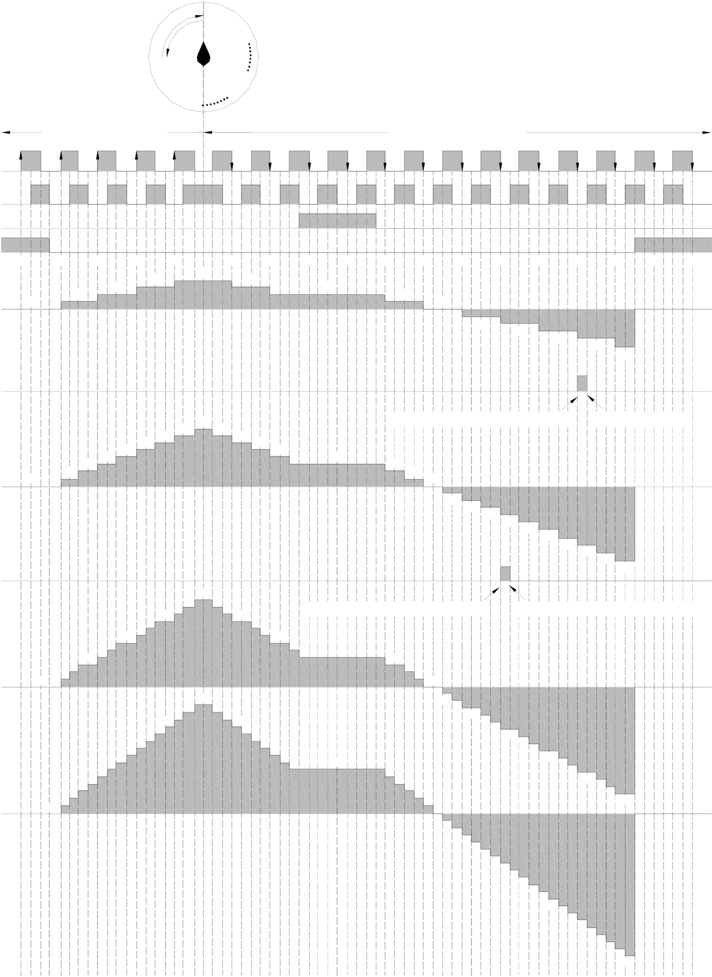
The diagram below is the waveform diagram for the relationship between counting and control of the four HSC modes in
this example when the PV value is set as at -4.
Retraced point
s t
Rotary encoder
Up counting Down counting (A phase ahead B phase) (B phase ahead A phase)
X8(A)
X9(B)
X10(M)
|
X11(C) |
o |
0 |
0 |
0 |
p |
q |
2 |
4 |
r |
3 |
s |
7 |
4 |
7 |
s |
3 |
5 |
r |
4 |
5 |
q |
p |
o |
n |
m |
l |
k |
j |
i |
h |
g |
||||||||||||||
|
MD4 |
|
CV(x1) |
|||||||||||||||||||||||||||||||||||||||||||
|
1 |
2 |
1 |
0 |
0 |
|||||||||||||||||||||||||||||||||||||||||
|
PV=-4 |
0 |
1 |
2 |
3 |
5 |
6 |
8 |
6 |
-1 |
-2 |
-3 |
-4 |
-5 |
||||||||||||||||||||||||||||||||
|
HSC2I |
|||||||||||||||||||||||||||||||||||||||||||||
|
HSC2 sends interrupt to CPU |
CPU receives and handles this interrupt |
||||||||||||||||||||||||||||||||||||||||||||
|
3 |
2 |
1 |
0 |
||||||||||||||||||||||||||||||||||||||||||
|
CV(x2) |
|||||||||||||||||||||||||||||||||||||||||||||
|
PV=-4 |
123 |
6 |
6 |
9 |
9 |
12 |
9 |
9 |
6 |
-1 |
-2-3-4-5 |
-6-7-8-9-10 |
|||||||||||||||||||||||||||||||||
|
MD5 |
|||||||||||||||||||||||||||||||||||||||||||||
|
HSC2I |
|||||||||||||||||||||||||||||||||||||||||||||
|
HSC2 sends interrupt to CPU |
CPU receives and handles this interrupt |
||||||||||||||||||||||||||||||||||||||||||||
|
MD6:CV(x3) |
4 |
3 |
2 |
1 |
0 |
||||||||||||||||||||||||||||||||||||||||
|
15 |
|||||||||||||||||||||||||||||||||||||||||||||
|
12 |
12 |
||||||||||||||||||||||||||||||||||||||||||||
|
-1-2-3 |
|||||||||||||||||||||||||||||||||||||||||||||
|
-6 |
|||||||||||||||||||||||||||||||||||||||||||||
|
6 |
5 |
3 |
-9 |
-12 |
|||||||||||||||||||||||||||||||||||||||||
|
MD7:CV(x4) |
1 |
2 |
3 |
||||||||||||||||||||||||||||||||||||||||||
|
1 |
0 |
-15 |
|||||||||||||||||||||||||||||||||||||||||||

-1
-3
-6
-9
-12
-20
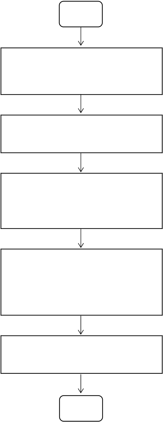
10.3Procedure for FBs-PLC High-Speed Counter Application
Start
|
z Configure HSC counting mode and respective input z Complete hardware wiring z Set HSC initial CV value and interrupt PV value in the main program z Write necessary handling z Start the operation |
1. Please refer to Section 10.2 for respective HSC counting modes and |
|
|
————- |
principles. |
|
|
2. Please refer to Section 10.4 for setting examples. ————-1. Please refer to “Digital Input Circuit” in Chapter 6 “Hardware Manual” for hardware wiring. 1. If the HSC is HHSC, it is necessary to apply FUN93 to load it into the |
||
|
————- |
HHSC CV and PV in the SoC chip. |
|
|
2. Please refer to Section 10.5 for program examples. 1. Please refer to Section 9.1 for subroutine structure. |
||
|
————- |
2. Please refer to Section 10.5 “Actual Examples” for program |
|
|
examples. ————-. Please refer to Section 10.5 for program examples and description. |
||
End
10.4HSC/HST Configuration
|
10.4.1 HSC/HST Configuration (Using FP-08) |
The screen of FP-08 will be taken as an example to describe HSC Configuration in this section. The HSC Configuration, in sequence, includes the following 5 items:
c Select assignment for HSC/HST (only HHSC provides this item selection function). Proceed to next item if selection is HSC. No other items are required if configured as HST.
dAssign respective HSC counting modes (MD0~MD7). After keying in the mode number, FP-08 will automatically display the HSC counting and control input names of the mode and reserve space for users to key in the external input point number Xn. The blank mode field indicates the HSC is not in use.
eDetermine whether the respective counting inputs (U, D, P, R, A and B) and control inputs (M and C) are to be applied or not (reserve the space if not in use and fill in the Xn value if it is to be applied. As respective Xn input values of HHSC are fixed, it requires only to key in alphabet “X” and FP-08 will automatically make up the preset number n).
fSelect whether the polarity of each HHSC counting input (U, D, P, R, A and B) is inverse or not, so as to match the polarity of the encoder (0: Not inverse, 1: Inverse. Preset as 0).
gSelect whether the polarity of each HHSC control input (M and C) is inverse or not, so as to match the polarity of the encoder (0: Not inverse, 1: Inverse. Preset as 0).

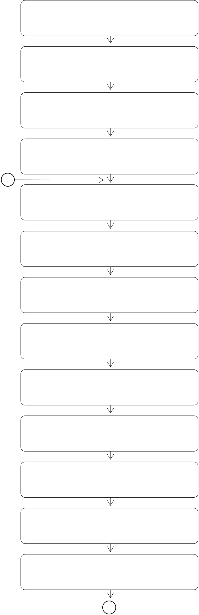
Examples applying FP-08 to perform the above mentioned c~g configurations
|
【Key Operation】 |
【LCD Display】 |
•••••••••••••••
•
•••••••••••••••
•
••••••••••••••
••••••••
•••••••••••••
••••••••••
••••••••••••••
••••••••••••••
C
•••••••••••••••
••••••••••••••
•••••••••••••••
••••••••••••••
•••••••••••••••
••••••••••••••
•••••••••••••••
••••••••••••••
•••••••••••••••
•
y HSC0 is preset as HSC
y HSC1 is preset as HSC
y HSC1 is used as a high-speed counter
HST1
y HSC2 is preset as HSC
y HSC3 is preset as HSC
••••••••• y MD field is blank indicating that HSC0 is not in use
••••••••• y There is no need to configured HSC1 as it has been set to HST (No Display).
y MD field of HSC2 is blank indicating MD is ••••••••••••• not in use
•••••••• *y After 7 is keyed in, the respective MD7 input names will be displayed and the
|
a |
••••••••••••• |
preset values for A and B (X8 and X9) will |
|
••••••••••• |
be filled automatically |
|
|
b |
y If MASK is required, just key in X and it will |
|
|
automatically fills number 10 |

【Key Operation】 【LCD Display】
b
•••••••••
••••••••••••••
••••••
••••••••••••••
•••••••••
y Key in 2 and the preset number of P will be filled automatically
y Move the cursor to R and key in “X”, it will immediately change to X13 and change it to be hardware direction
|
••••••••• |
control |
y HSC4 is not in use
|
••••••••• |
y HSC5 is not in use |
•••••••••
•••••••••••
••••••
••••••••••••••
y HSC6 is set as MD0 and respective input names of MD0 SHSC will be displayed automatically
y Assign X10 as the up counting pulse
••••••“U” for HSC6
••••••••••••••y Assign X2 as the down counting pulse
••••••••• “D” for HSC6
••••••••y HSC7 is not in use
*
|
••••••••••••••••••••••••••••• •••••••••••••••••••••••••••• •••••••••••••••••••••••••••• ••••••••••••••••••••••••••••• •••••••••••••••••••••••••••••• |
y All counting inputs of every non-inverse y All MASK controls of HHSC are preset as non-inverse y Change all MASK inputs of HHSC to inverse (i.e. the MASK function y All CLEAR controls of HHSC are preset as non-inverse y Complete configuration and return to the initial screen display (HSC0/HST0 Item Selection) |
C
|
z Input value modification can be made by directly key in the new value to overwrite. Use |
|
key to delete any input |

value, if required.
z A blank field (without any value input) indicates the application of the HSC or the input is not required. z “pulse” in the previous example represents the “Counting Input”, i.e. U and D, P and R or A and B, of HHSC. z “POLAR” represents “POLARITY”, i.e. selection of inverse or non-inverse.
z The input point for respective HHSC counting and control inputs are fixed. Therefore, in the “Configuration Examples” of the previous example, it needs only to key in “X” for each HHSC input to indicate that the input is to be applied and FP-08 or WinProladder will automatically make up the preset number for X, to which no change will be allowed. The user may assign respective SHSC counting or control inputs between X0~X15 freely. Hence, it is necessary to key in both the “X” and the number n for SHSC input point number to make it complete.
|
10.4.2 HSC/HST Configuration (Using WinProladder) |
Click the item “I/O Configuration” which in Project Windows :
|
Project name |
||||||
|
S |
stem Co |
nfigurat |
on |
|||
I/O Configuration Æ Select “Timer/Counter”
When “Timer/Counter” window appear then you can choose the Timer or Counter which you want.
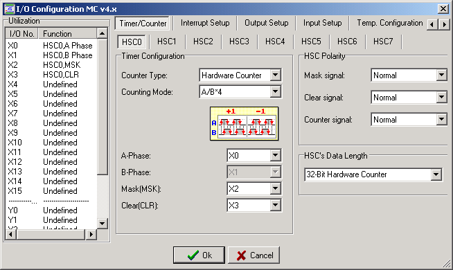
—《Timer/Counter Configuration》—
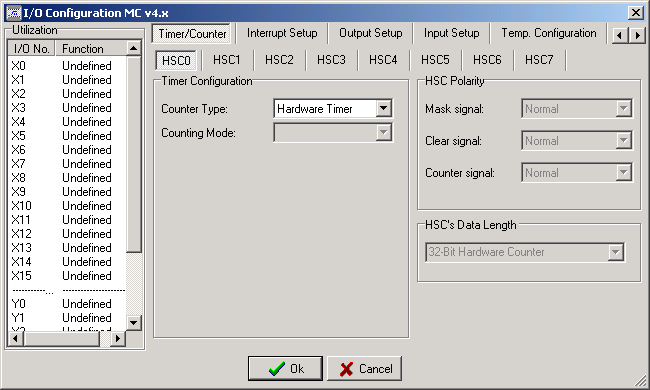
【Counter Type 】: It can select Hardware Counter or Hardware Timer.
【Counting Mode 】: It can select the Counting Mode( Example: U/D、P/R、A/B……)
【A-Phase 】: Select the up pulse input signal. If the Mode is P/R Counting Mode ,and this item will be “PLS”; If the Mode is U/D Counting Mode ,and this item will be “UP”.
【B-Phase 】: Select the down pulse input signal. If the Mode is P/R Counting Mode ,and this item will be “DIR”; If the Mode is U/D Counting Mode ,and this item will be “DN”.
【Mask[MSK] 】: It can select Mask input.
【Clear[CLR] 】: It can select Clear input.
—《HSC Polarity》area —
【Mask signal 】: Determining Mask signal is positive or negative.
【Clear signal 】: Determining Clear signal is positive or negative.
【Counter signal 】: Determining Counter signal is positive or negative.
—《HSC’s Data Length》area —
It can choose 32-bit Hardware Counter mode or 16-bit Timer + 16-bit Counter mode. 32-bit Hardware Counter mode means using two register to record the Counting value. The 16-bit Timer + 16-bit Counter mode means using one register to record Counting value and the other register will be cyclic Timer.
All preset or selectable input point numbers, software MASK, software CLEAR, direction selection and other related numbers of HHSC and SHSC are summarized in the table below:
|
Type |
HHSC |
MA/MC/MN |
SHSC |
Signal
|
Allowed |
HSC0 |
HSC1 |
HSC2 |
HSC3 |
HSC4 |
HSC5 |
HSC6 |
HSC7 |
||||
|
DR4096 DR4100 |
DR4104 |
DR4108 |
DR4112 |
DR4116 |
DR4120 |
DR4124 |
||||||
|
CV Register |
||||||||||||
|
PV Register |
DR4098 DR4102 |
DR4106 |
DR4110 |
DR4114 |
DR4118 |
DR4122 |
DR4126 |
|||||
|
Counting |
U,P or A |
X0 |
X1/X4 |
X4/X5/X8 |
X5/X12 |
X0~X15 |
X0~X15 |
X0~X15 X0~X15 |
||||
|
Input |
D,R or B |
X1 |
X5 |
X9 |
X13 |
X0~X15*X0~X15*X0~X15* X0~X15* |
||||||
|
X0~X15 |
X0~X15 |
X0~X15 X0~X15 |
||||||||||
|
Control |
Mask |
X2 |
X6 |
X10 |
X14 |
|||||||
|
Input |
Clear |
X3 |
X7 |
X11 |
X15 |
X0~X15 |
X0~X15 |
X0~X15 X0~X15 |
||||
|
M1982 |
M1984 |
M1986 |
M1988 |
|||||||||
|
Software MASK |
||||||||||||
|
M1940 |
M1946 |
M1976 |
M1979 |
|||||||||
|
Relay |
||||||||||||
|
Software CLEAR |
M1941 |
M1947 |
M1977 |
M1980 |
Clear the Current Value Register directly |
|||||||
|
Relay |
||||||||||||
Software Direction
|
Selection(MD2,3 |
M1942 |
M1948 |
M1978 |
M1981 |
M1983 |
M1985 |
M1987 |
M1989 |
Only)
|
Interrupt Subroutine |
HSC0I |
HSC1I |
HSC2I |
HSC3I |
HSC4I |
HSC5I |
HSC6I |
HSC7I |
|
Label |
* When SHSC works in MD2(P/R), direction chose by special relay M1983、M1985、M1987 and M1989.
z When working in A-B Mode(HHSC as MD4~MD7、SHSC as MD4), whose A/B input must be used in pair, as X8 and X9.(even number is A-Phase and odd number is B-Phase)
z The input point of X0~X15 in the table above can only be assigned once (i.e. used as one function), which can’t repeat to be used.
z FBs-MN’s frequency can reach up to 460 KHz.( single phase and AB phase)
z FBs-MC’s frequency can reach up to 100 KHz. ( single phase and AB phase)
z FBs-MA’s frequency can reach up to 20KHz (single phase), and 10KHz (double phase).
z The total input frequencies of SHSC can’t be exceed 8 KHz; the higher the frequency, the more it occupy the system
(CPU) time, and the scanning duration will be extended abruptly.
z MA only support SHSC.



















10.5Examples for Application of High-Speed Counter
|
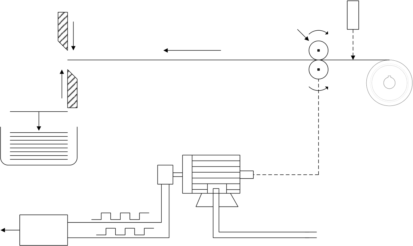
Example 1 This example uses high-speed counter for equal-length cutting control. |
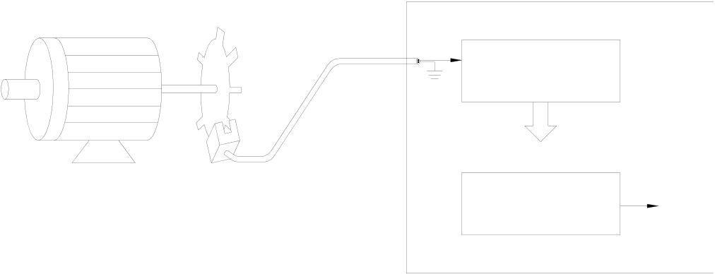
Mechanism

|
HSC configuration (Just set HSC0 to MD7 and complete the configuration) |
|

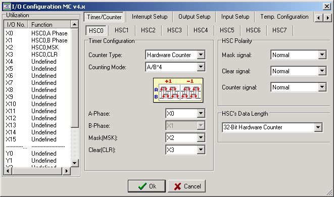
|
Control program |
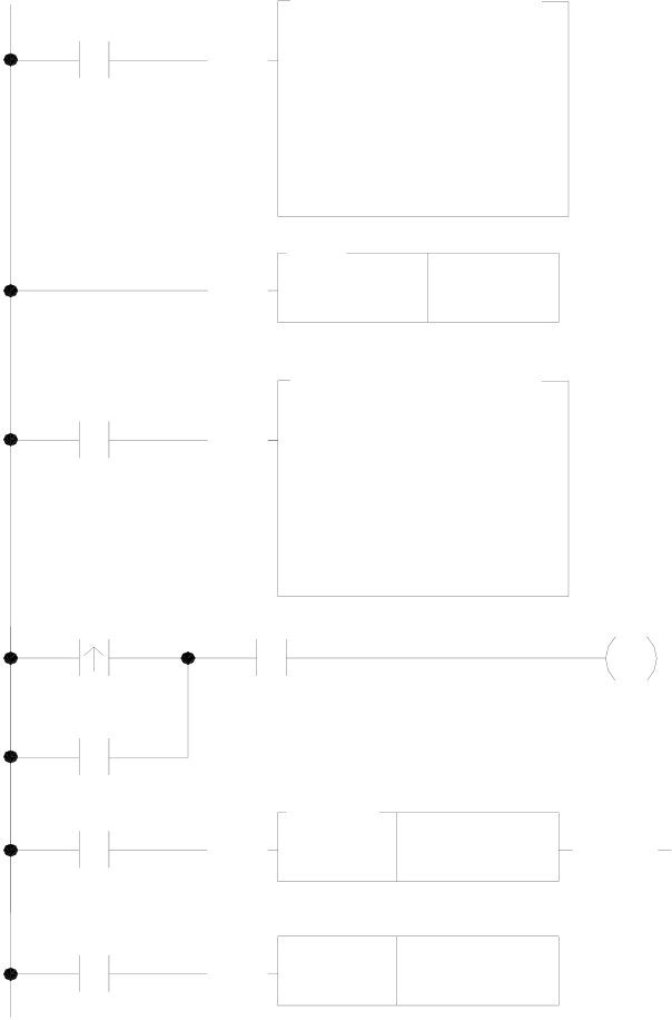
【Main Program】
|
X4 |
93DP.HSCTW |
Y0 |
• Use FUN 93 to write the contents of the current value |
|||
|
EN |
S : |
0 |
register into the CV register of HSC0 in the SoC chip |
|||
|
X4 |
CN: |
HSC0 |
CN =0 indicates HSC0 |
|||
|
D : |
CV |
D |
=0 indicates CV |
|||
|
92 |
• Use FUN 92 to read the counting value of the HSC0 CV |
|||||
|
EN |
HSCTR |
HSC0 |
||||
|
register in the SoC chip (store into DR4096) |
||||||
|
93DP.HSCTW |
||||||
|
• Store the counting of cutting length DR0 into DR4098 and |
||||||
|
EN |
S : |
R0 |
use FUN93 to store the value into the PV register of HSC0 |
|||
|
CN: |
HSC0 |
in the SoC chip |
||||
|
X4 |
D : |
PV |
CN =0 indicates HSC0 |
|||
|
X2 |
D |
=1 indicates PV |
||||
|
Y0 |
.01S |
TUP |
• Start the motor |
|||
|
Y1 |
||||||
|
T0 |
EN |
T0 |
10 |
• Turn the cutter Y1 ON for 0.1 second |
||
|
EN |
RST |
Y1 |
||||
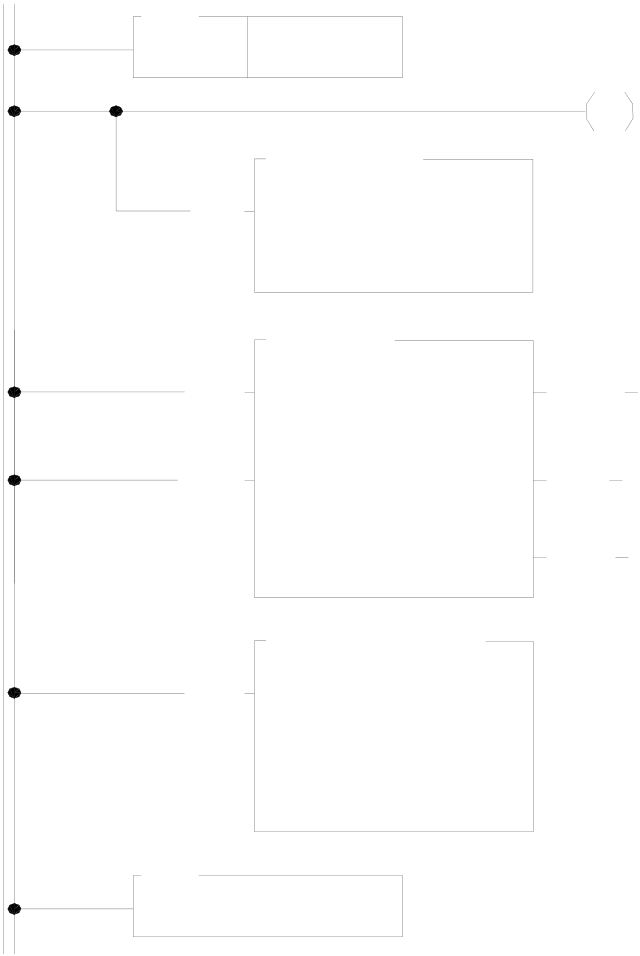
【Subroutine】
|
65 |
H SC 0I |
Y1 |
• When HSC0 CV=PV in the SoC chip, the hardware will |
||
|
LBL |
|||||
|
automatically execute the interrupt subroutine labeled HSC0I |
|||||
|
EN |
74.IM D I0 |
D =0 |
• When counting is up, turn Y1 ON (to cut materials) |
||
|
D : |
Y1 |
||||
|
N : |
1 |
||||
|
• Output Y1 immediately to reduce the error caused by scan |
|||||
|
EN |
11D .(+) |
||||
|
time |
|||||
|
Sa : |
R 4098 |
||||
|
U /S |
Sb : |
: R 0 |
C Y |
• Calculate new cutting position and load HSC0 PV |
|
|
D : |
R 4098 |
||||
BR
93D .H SC TW
|
EN |
S : |
R 4098 |
|
C N : |
H SC 0 |
|
|
D : |
PV |
69
R TI
【Description】
1. The main program will initialize the HSC0 CV (CV=0) in advance and move the cropping length (DR0) to the HSC0 PV
before starts Y0 to turn on the motor for material conveying.
2. When CV reaches PV, the length of R0 is added to the PV before being reloaded into HSC0 PV.
3. When all materials are rolled out, the material shortage detector X2 will be ON and stop the motor.
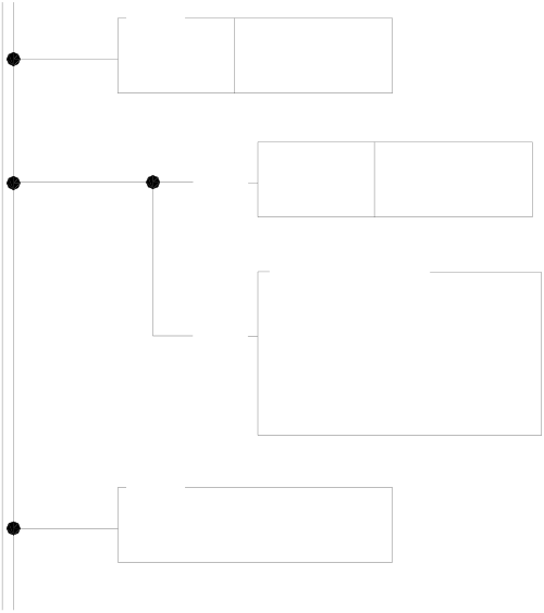
|
Example 2 Example of high speed counting up action processed by Interrupt |
【Main Program】
|
M100 |
EN |
93DP.HSCTW |
•Employ FUN93 to write the content of current value register into the |
||
|
S : |
0 |
CV of HSC0 in SoC chip (reset) |
|||
|
CN =0, represents HSC0 |
|||||
|
CN: |
HSC0 |
||||
|
D |
=0, represents CV |
||||
|
D : |
CV |
||||
|
M100 |
EN |
92 |
•Employ FUN92 to read out the current counting value of HSC0 |
||
|
HSCTR |
HSC0 |
||||
|
in SoC chip, and store it into the CV register (DR4096) |
|||||
|
M101 |
EN |
P |
CN=0, represents HSC0 |
||
|
SET |
Y0 |
•As M101 change from 0→1, start Y0 ON (begin to operate) |
|||
|
EN |
93DP.HSCTW |
•Employ FUN93 to write the content of preset register into HSC0 PV |
|||
|
S : |
R0 |
||||
|
in SoC chip, which serves as setting value of counting up interrupt |
|||||
|
CN: |
HSC0 |
||||
|
CN=0, represents HSC0 |
|||||
|
D : |
PV |
||||
|
D =1, represents PV |
|||||
【Subroutine】
|
65 |
HSC0I |
Y0 |
• Hardware high speed counter #0 interrupt label |
|
LBL |
|||
|
EN |
RST |
• When time up, it sets Y0 OFF (stop) |
|
|
• Let Y0 out immediately, so as to stop promptly |
|||
|
74.IMDI0 |
|||
|
EN |
Y0 |
||
|
D : |
|||
|
(otherwise Y0 will have a scan time output delay) |
|||
|
N : |
1 |
69
RTI

|
Example 3 Example of Immediate response of multi-zone high speed counting up by Interrupt Processing |
【Main program】
|
X3 |
EN |
92 |
• Employ FUN92 to read out the current value of HSC1 in SoC |
||
|
chip, and store it into current value register DR4100 |
|||||
|
HSCTR |
HSC1 |
||||
|
CN =1, represents HSC1 |
|||||
|
M101 |
EN |
P |
• As M101 change from 0→1, clears the pointer register to 0 |
||
|
RST |
R100 |
||||
|
EN |
P |
• Clears the flag of the last zone to be OFF |
|||
|
RST |
M110 |
||||
|
EN |
93DP.HSCTW |
• Employ FUN93 to write preset register content into HSC1 |
|||
|
S : |
R200 |
||||
|
PV in SoC chip, which serve as counting up setting value. |
|||||
|
CN: |
HSC1 |
||||
|
CN =1, represents HSC1 |
|||||
|
D : |
PV |
D |
=1, represents PV |
||
114P.Z-WR
|
EN |
D : |
Y8 |
ERR |
• Clear Y8~Y15 to be OFF |
|
1/0 |
N : |
8 |
P
|
EN |
SET |
Y8 |
• Set Y8 ON, it represents that it is at the zone 0 currently |
|
|
EN |
74P.IMDI0 |
• Set Y8~Y15 output t immediately |
||
|
D : |
Y8 |
|||
|
N : |
8 |
|||
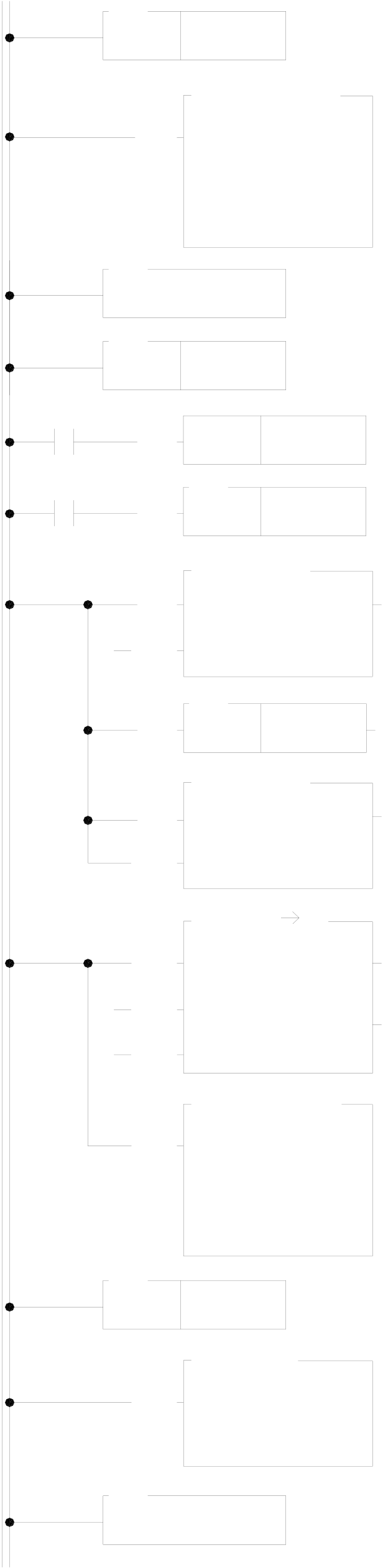
【Subroutine】
|
65 |
X3+I |
• Label name for the X3 rising edge interrupt service |
|
|
LBL |
|||
|
subroutine of X3+1 |
|||
|
93D.HSCTW |
|||
|
(it must assign X3 to be the rising edge interrupt input) |
|||
|
EN |
|||
|
• When X3 changes from 0→1,employ FUN93 to write the |
|||
|
S : |
0 |
||
|
CN: |
HSC1 |
current register content to the HSC1 CV in SoC chip (reset). |
|
|
CN = 1, represents HSC1 |
|||
|
D : |
CV |
||
|
D = 1, represents CV |
|||
69
RTI
|
M110 |
65 |
HSC1I |
Y15 |
• Labeled as HSC1I hardware high speed counter interrupt |
|
LBL |
||||
|
service subroutine. |
||||
|
M110 |
EN |
RST |
• Turn Y15 OFF when the last zone finished. |
|
|
66 |
||||
|
EN |
JMP |
110 |
41.BITWR
|
EN |
D : |
WY8 |
ERR |
• Make the previous zone output OFF |
|
INB |
N : |
R100 |
OVF |
|
|
15 |
• Set the pointer point to the next zone |
|||
|
EN |
R100 |
|||
|
(+1) |
41.BITWR
|
EN |
D : |
WY8 |
ERR |
M110 |
• Set the output of next zone to be ON |
||
|
INB |
N : |
R100 |
END |
||||
|
101D.T R |
• Move the counting value of next zone (beginning from |
||||||
|
EN |
|||||||
|
Ts : |
R200 |
||||||
|
DR200 pointer pointed register) to the preset register |
|||||||
|
L : |
8 |
ERR |
|||||
|
INC |
|||||||
|
DR4102 |
|||||||
|
Pr : |
R100 |
||||||
|
CLR |
• When it’s the last zone, the M110 is ON |
||||||
|
Rd : |
R4102 |
||||||
|
EN |
93D.HSCTW |
• Employ the FUN93 to write the preset value into the HSC1 |
|||||
|
S : |
R4102 |
PV in the SoC chip, which serves as counting up interrupt |
|||||
|
setting point. |
|||||||
|
CN: |
HSC1 |
||||||
|
CN =1, represents HSC1 |
|||||||
|
D : |
PV |
||||||
|
D |
=1, represents PV |
||||||
65
|
LBL |
110 |
Y8 |
• Y8~Y15 output transmitting immediately |
|
EN |
74.IMDI0 |
||
|
D : |
|||
|
N : |
8 |
69
RTI
10.6FBs-PLC High-Speed Timer
The minimum timing unit (time base) of an ordinary PLC can only reach 1mS, on which the deviation in scan time should also be added. Therefore, it is necessary to apply high-speed timer (HST) if a more precise timing (e.g. using timer to cooperate with HSC for frequency measurement) is required.
FBs-PLC is built in a high-speed timer (HSTA) with a time base of 16-bits/0.1mS and, as described previously, four 32-bit high-speed counters (HSC0~HSC3) of HHSC that can work as the high speed timer (HST0~HST3) with a time base of 32-bit/0.1mS for using. Thus, FBs-PLC can have up to five high-speed timers. As HSC and INT, all HST can be enabled or disabled (default as enable) by the instructions EN (FUN145) and DIS (FUN146). HSTA and HST0~HST3 are respectively described as below.
The finest time base for most of the ordinary PLC is 10mS. Though some PLC may have HST with a time base of 1mS. When deviations in the PLC scan time is taken into consideration (e.g. if the scan time is 10mS when the time base is 1mS, the total deviation still exceeds 10mS), the figure of 1mS becomes meaningless. Therefore, these PLCs can’t be applied in high precision timing. FBs-PLC, having a time base of 0.1mS, has no deviation in scan time for its time up is sent out by interrupt to provide a precision 100 times better than ordinary PLCs’ timer application and can be used for many applications demanding precision timing.
10.6.1HSTA High-Speed Timer
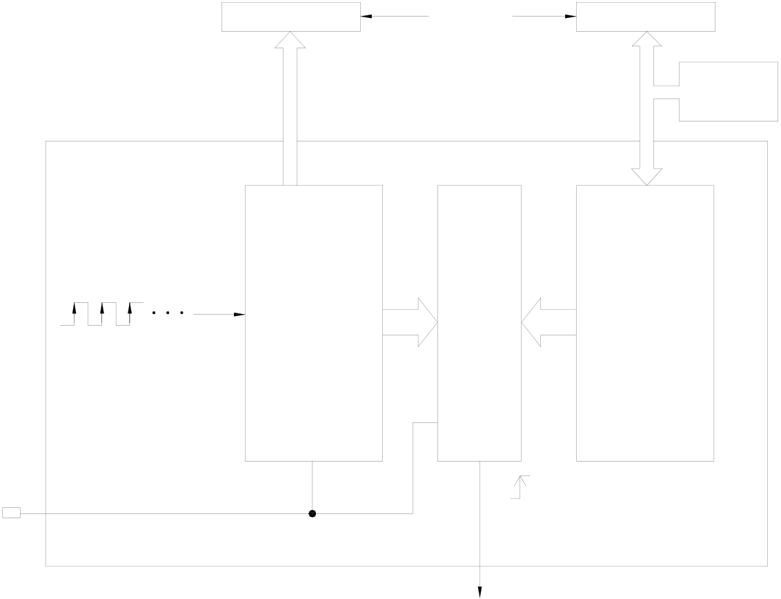
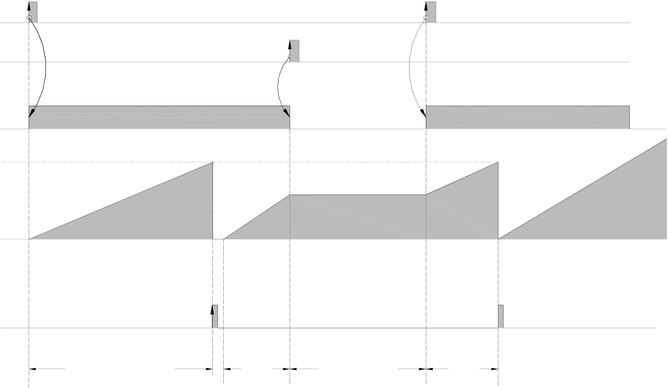
HSTA is a 16-bit hardware timer built in the SoC chip. As HHSC, it must use the instruction FUN93 (HSCTW) to load the PV to the HSTA PV in the chip, and with the instruction FUN92 (HSCTR) to read for CV. HSTA can be used as a timer having two different functions. FBs-PLC will use it as a general 16-bit delay timer when PV ≥2 and as a 32-bit cyclic timer when PV=0.
|
A. HSTA 16-bit high-speed delay timer (Timely interrupt timer) |
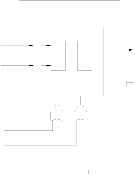
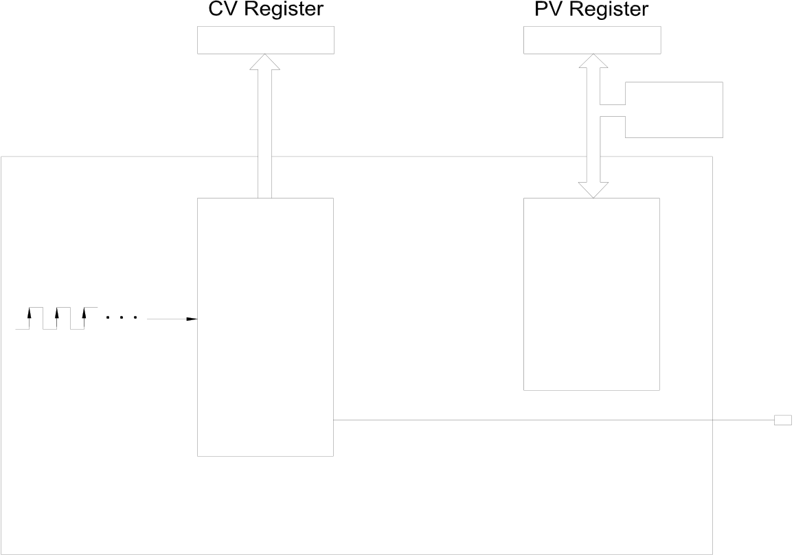
After HSTA starts timing, the delay timer will delay for a time of PVx0.1mS before sending an interrupt out. When PV>0, HSTA served as a delay timer which is 16-bit and its PV value can be set as 0002H~FFFFH. i.e. the delay time can be set as 0.2mS~6.5535 seconds. Except that having a more precise time base and being able to send an interrupt out immediately at time-up to provide a much higher timing precision, the applications of HSTA are the same as an ordinary delay timer. The diagram below is the structure diagram for HSTA being used as a delay timer. Please refer to Section 10.6.3 “Program Examples” for detailed function and application.
|
CV Register |
(HSTA) |
PV Register |
z Apply FUN93 to write the |
|
R4152 |
R4154 |
||
|
(SoC Chip) |
PV into preset register of |
||
|
FUN92 |
|||
|
FUN93 |
HSTA high speed timer in |
||
|
(HSCTR) |
SoC chip, which serves as |
||
|
(HSCTW) |
|||
|
timely interrupt timer (for |
every set point of timer it
|
16 bit |
16 bit |
perform once the timely |
|
interrupt subroutine with |
label name of “HSTAI”).
|
UP |
CV |
PV |
0.1mS time base
EN/DIS
EN/DIS
EN(FUN145)/
|
DIS(FUN146) |
PV=CV |
Interrupt label
HSTAI
EN(FUN145)
DIS(FUN146)
Timing/Non-timing
PV≧2 PV
CV
(R4152)
HSTAI
|
Td=0.1mS x PV |
Td1 |
Non-timing |
Td2 |
Td=Td1 + Td2 |

B. HSTA 32-bit high-speed cyclic timer
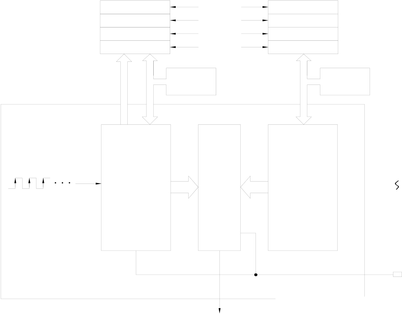
The so-called “Cyclic Timer” is a timer that add 1 to its current value for every fixed interval and will persistently carry out up counting cyclic timing. Its CV value will cycle around as 0, 1, 2, … 2147483647, 2147483648, 2147483649, …… 4294967295, 0, 1, 2, … (as the time base is 0.1mS, CV value x 0.1mS will be its accumulative time). In fact, the cyclic timer is an up counting cyclic timing clock having a time base of 0.1mS that can operate endlessly and be used to read any two events at the time when they occurred and to calculate the time interval between the occurrence of the said two events. The Diagram B as shown below is the structure diagram for HSTA being used as a 32-bit cyclic timer. As shown in diagram, when cyclic timer PV=0, it will not send out the interrupt. To obtain the timing value, it is necessary to use FUN92 to access the CV value from the SoC chip and save it to the 32-bit CV register (DR4152) in the PLC. The typical application of the cyclic timer is for more precision of turning speed (RPM) detection under the circumstances when the change in turning speed (RPM) is huge or when it is extremely low. Please refer to Example of Section 10.6.3 for description.
|
z Employ FUN92 to read out the CV |
DR4152 |
(HSTA) |
R4154 |
FUN93 |
z Employ FUN93 to write the PV=0 to |
|
|
of HSTA high speed counter in SoC |
||||||
|
HSTA high speed timer set point |
||||||
|
chip and store it into CV register |
||||||
|
register to make it serve as 32-bit |
||||||
|
(DR4152) so as to let the user know |
FUN92 |
(SoC Chip) |
16 bit |
|||
|
cyclic timer. |
||||||
|
the value for time lapsed. |
||||||
|
(HSCTR) |
||||||
|
(HSCTW) |
||||||
|
16 bit |
||||||
|
UP |
CV |
PV |
||||
0.1mS Time base
|
4294967295 |
0 |
1 |
EN/DIS |
2147483647 |
2147483648 |
2147483649 |
EN(FUN145)/ |
0 |
|
DIS(FUN146) |
||||||||
|
2 |
4294967295 |
0.1mS
10.6.2HST0~HST3 High-Speed Delay Timer
|
A. HST0~HST3 high-speed delay timer (Timely interrupt timer) |
HHSC (HSC0~HSC3) can be configured as four 32-bit high-speed delay timers, HST0~HST3. They have the same functions and time base as a 16-bit HSTA delay timer except that HST0~HST3 are 32-bit to plan HHSC as HST only needs to select “1” in the HSC/HST Item Selection under Item 8 “HSC/HST/INT” of FP-08 or WinProladder “Configuration”. Please refer to the example (to configure HSC1 as HST1) in Section 10.4 “HSC/HST Configuration”. The diagram below is the function structure diagram for HHSC being planned as a HST. Its applications are the same as that of a 16-bit HSTA. Please refer to Section 10.6.4 “Program Examples”.
|
z Employ FUN92 to read out the current |
CV Register |
z Apply FUN93 to write |
||
|
timing value in SoC chip and store it into |
PV Register |
the PV into the SoC chip which is served as set point for timing up |
||
|
the CV register of CPU. So as to let |
||||
|
user know the current timing value. |
(CPU Internal Memory) |
|||
|
z It may also employ FUN93 to write the |
DR4096 |
(HST0) |
DR4098 |
interrupt. |
|
CV into the SoC chip so as to reset the |
DR4100 |
(HST1) |
DR4102 |
|
|
timing value. |
DR4104 |
(HST2) |
DR4106 |
|
|
DR4108 |
(HST3) |
DR4110 |
||
|
FUN92 |
FUN93 |
FUN93 |
||
|
(HSCTR) |
(HSCTW) |
(HSCTW) |
||
(SoC Chip)
|
0.1mS time base |
UP |
CV |
PV |
(HST0) |
|
(HST3) |
EN/DIS
EN/DIS
EN(FUN145)/
DIS(FUN146)
|
TO CPU |
Interrupt label Interrupt label |
|
|
(HST0) |
HST0I |
|
|
(HST1) |
HST1I |
|
|
(HST2) |
HST2I |
|
|
(HST3) |
HST3I |
|
B. HST0~HST3 32-bit cyclic timer
According to demand, configured the HHSC(HSC0~HSC3) to be the 32-bit timers of HST0~HST3. For interval of every 0.1mS, the current timing value register in SoC chip will be increased by 1. User may use FUN92 instruction to read out the current timing value and store it into the CV registers (DR4096, DR4100, DR4104, and DR4108) of CPU. Therefore the content of CV register of CPU become 0, 1, 2, ……, 7FFFFFFFH, 80000000H, ……., FFFFFFFFH, 0, 1, …… etc. variation of values for 32-bit. With the timing calculation technique to count the interval between two events, it can obtain infinite number of 0.1mS 32-bit timers.
10.6.3Examples for Application of High-Speed Timer HSTA
|
Example 1 HSTA serve as 32-bit cyclic timer |
|
M1 |
EN |
93DP.HSCTW |
• Employ FUN93 to write the preset value into the HSTA PV in the SoC |
|||
|
S : |
0 |
chip |
||||
|
CN =4, represents HSTA |
||||||
|
CN: |
HSTA |
D =1, represents PV |
||||
|
D : |
PV |
|||||
• Employ FUN 92 to read out the current timing value of HSTA in SoC
|
M1 |
EN |
92 |
chip and store it to DR4152 |
|
HSCTRHSTA |
(DR4152 value change from 0,1,2, ……,FFFFFFFF,0,1,2,……cyclic |
||
|
variation, the unit is 0.1mS) |
• CN =4, represents HSTA
Example 2 Application example for cyclic timer
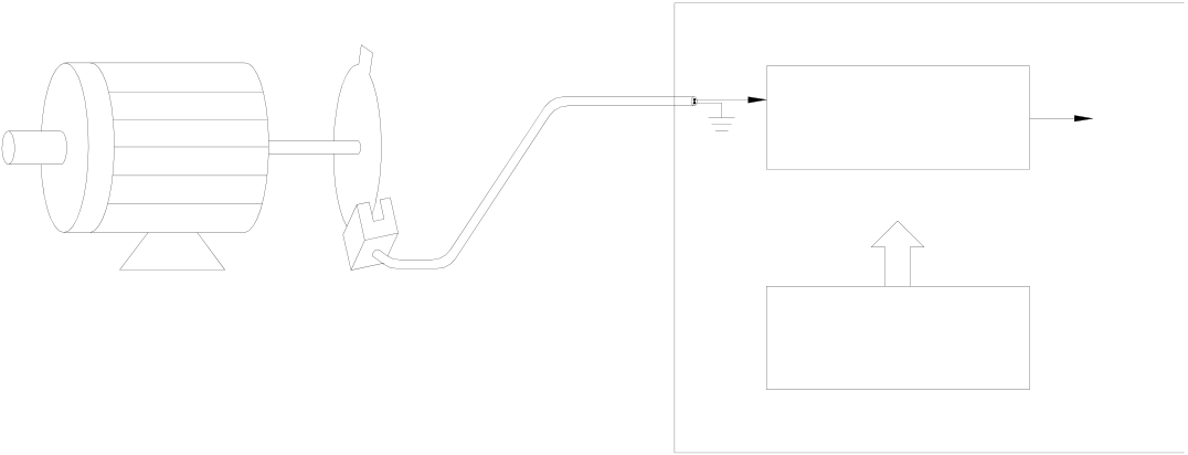
This example uses HSTA as a cyclic timer, cooperating with HSC0, to read the time interval for accumulation of 10 pulses and sending an interrupt out each time as 10 pulses are accumulated and, reciprocally, find out the required RPM (the number of pulses is fixed when the time varies).
|
Mechanism |
|
Motor |
X0 |
U |
PLC |
INT |
|
HSC0 |
FUN92
|
(Y0 motor driving) |
Light chopper |
HSTA |
|
(X1 starting switch) |
(1 pulse/revolution) |
|
HSC and HST configuration |
c As HSTA is built in, no configuration is required. Simply make PV =0 to make it as a 32-bit cyclic timer.
d To cooperate with the photo interrupter, set the HSC0 as an up counting counter having single input
(MD0, but use only U input).
※ All other settings (polarity of counting and control inputs) are preset (non-inverse) and should not be changed.
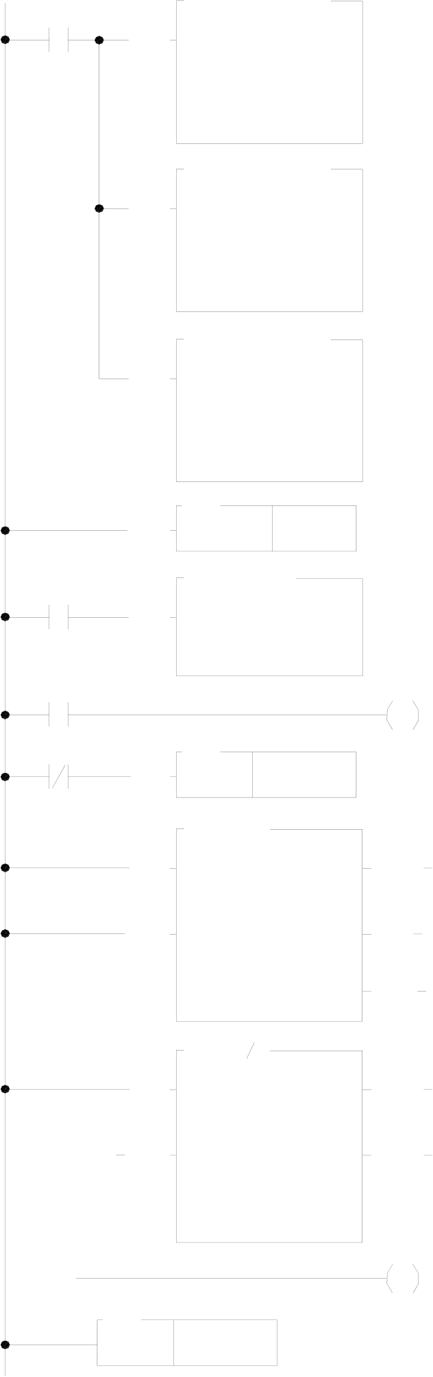
【Main Program】
|
M1924 |
EN |
93D.HSCTW |
Y0 |
•Employ FUN93 to write current value 0 into the CV of HSC0 in |
|||||||||||||||||||||
|
SoC chip (reset) |
|||||||||||||||||||||||||
|
S : |
0 |
||||||||||||||||||||||||
|
M1924 |
CN =0, represents HSC0 |
||||||||||||||||||||||||
|
CN: |
HSC0 |
||||||||||||||||||||||||
|
D |
=0, represents CV |
||||||||||||||||||||||||
|
D : |
CV |
||||||||||||||||||||||||
|
EN |
|||||||||||||||||||||||||
|
93D.HSCTW |
• Write 10 into the preset register in SoC chip, which acts as |
||||||||||||||||||||||||
|
S : |
10 |
||||||||||||||||||||||||
|
interrupt value for counting up; |
|||||||||||||||||||||||||
|
CN: |
HSC0 |
||||||||||||||||||||||||
|
FUN93 CN=0 indicates HSC0 and D=1 indicates PV |
|||||||||||||||||||||||||
|
D : |
PV |
||||||||||||||||||||||||
|
EN |
|||||||||||||||||||||||||
|
93D.HSCTW |
• Write 0 into the preset register, and HSTA is configured as a |
||||||||||||||||||||||||
|
S : |
0 |
||||||||||||||||||||||||
|
32-bit high-speed cyclic timer |
|||||||||||||||||||||||||
|
CN: |
HSTA |
||||||||||||||||||||||||
|
FUN93 CN=4 indicates HSTA and D=1 indicates PV |
|||||||||||||||||||||||||
|
D : |
PV |
||||||||||||||||||||||||
|
EN |
|||||||||||||||||||||||||
|
92 |
• Read the current timing value |
||||||||||||||||||||||||
|
HSCTR |
HSTA |
||||||||||||||||||||||||
|
08D.MOV |
|||||||||||||||||||||||||
|
EN |
S : |
R4152 |
• The initial value of HSTA CV register is stored to DR2 |
||||||||||||||||||||||
|
X1 |
|||||||||||||||||||||||||
|
D : |
R2 |
||||||||||||||||||||||||
|
M1 |
EN |
66 |
D=0 |
• Find interval for each HSC0 interrupt |
|||||||||||||||||||||
|
JMP |
1 |
||||||||||||||||||||||||
|
12D.(-) |
|||||||||||||||||||||||||
|
EN |
|||||||||||||||||||||||||
|
Sa : |
R2 |
||||||||||||||||||||||||
|
• |
Rotating |
speed |
= |
N |
× |
60 |
RPM |
||||||||||||||||||
|
Sb : |
R4 |
||||||||||||||||||||||||
|
U/S |
CY |
∆ |
T |
||||||||||||||||||||||
|
D : |
R6 |
||||||||||||||||||||||||
|
N=10, |
∆T |
= |
∆CV |
× |
0 |
. 1 m |
S |
(currentCV-previousCV) = 10000 S |
|||||||||||||||||
|
14D.( ) |
BR |
||||||||||||||||||||||||
|
Therefore |
rotating |
speed |
= |
6000000 |
RPM |
||||||||||||||||||||
|
EN |
D=0 |
∆ |
CV |
||||||||||||||||||||||
|
Sa : |
6000000 |
• R100=RPM |
|||||||||||||||||||||||
|
Sb : |
R6 |
ERR |
• Clear the calculation flag of RPM |
||||||||||||||||||||||
|
U/S |
|||||||||||||||||||||||||
|
D : |
R100 |
||||||||||||||||||||||||
|
M1 |
|||||||||||||||||||||||||
|
65 |
1 |
||||||||||||||||||||||||
|
LBL |
|||||||||||||||||||||||||
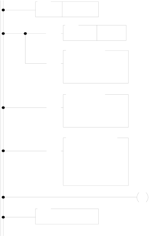

【Subroutine】
|
65 |
HSC0I |
HSTA |
• Each time when HSC0 accumulates 10 pulses, the |
|
LBL |
|||
|
hardware will automatically run this interrupt subroutine |
|||
|
EN |
92 |
• Read the HSTA CV |
|
|
HSCTR |
08D.MOV
|
EN |
S : |
R2 |
|
D : |
R4 |
08D.MOV
|
EN |
S : |
R4152 |
|
D : |
R2 |
93D.HSCTW
|
EN |
S : |
0 |
M1 |
• Reset the current value to 0 |
|
CN: |
HSC0 |
• M1=ON, RPM calculating flag |
||
|
D : |
CV |
69
RTI
X0
|
HSC0 |
8 |
9 |
10 |
1 |
10 |
1 |
9 |
10 |
1 |
|
|
|
CV value |
|||||||||||
|
HSC0I |
|
||||||||||
|
PV value |
10 |
10 |
10 |
10 |
10 |
10 |
|||||
|
CV value of HSTA V value of HSTA |
10000 |
15000 |
200000 |
800000 |
|||||||
|
(0.1mS time base) 1ms time basc) |
(1s) |
(1.5s) |
(20s) |
(80s) |
|||||||
|
∆T = |
DT = 0.5s |
RPM= |
∆T =10RPM |
RPM= |
|||||||
|
N |
|||||||||||
|
=1200RPM |
|||||||||||


 RPM= x60
|
Example 3 HSTA serve as timely interrupt timer program |
【Main Program】
• Set up the period of timely interrupt time. S=5 represents
|
M0 |
EN |
93DP.HSCTW |
that it performs the interrupt service subroutine with the |
||
|
S : |
5 |
label name of HSTAI every 0.5mS. |
|||
|
CN: |
HSTA |
•Employ FUN93 to write the preset value into HSTA PV in |
|||
|
D : |
PV |
||||
SoC chip, which serve as time up for interrupt preset value.
CN =4, represents HSTA
D =1, represents PV
【Subroutine】
|
65 |
HSTAI |
a=b |
• Interrupt service subroutine with the label name of HSTA. |
||
|
LBL |
|||||
|
EN |
92 |
• Read the current value of hardware high speed counter HSC0 |
|||
|
HSCTR |
HSC0 |
||||
|
once every 0.5mS. |
|||||
|
EN |
17D.CMP |
• To tell whether the current counting value is greater than or |
|||
|
Sa : |
R4096 |
||||
|
equal to R0. if yes, then Y0 will be ON. |
|||||
|
Sb : |
R0 |
a>b |
|||
|
U/S |
|||||
Y0
a<b
74.IMDI0
|
EN |
D : |
Y0 |
• Update output Y0 immediately, so as to reach the high speed |
|
output reaction |
|||
|
N : |
1 |
||
|
(otherwise there will be introduced a delay in scan time) |
69
RTI
10.6.4Examples for Application of High-Speed Timer HST0~HST3
HSC and HST configuration(Using WinProladder)
Click the item “I/O Configuration” which in Project Windows :
System Configuration |
||||||||||
I/O Configuration Æ Select “Timer/Counter”
●When “Timer/Counter” windows appear, then you can choose the “Hardware Timer” in Counter Type item, then HHSC (Hardware High Speed Counter) can configure to be HHT.(Hardware High speed Timer)
●User don’t have to configure the HSTA, because the HSTA is default. Only you want HHSC(Hardware High Speed Counter) to be HHT.(Hardware High speed Timer) and you have to configure it.
|
HSC and HST configuration(Using FP-08) |
•••••••••••••••••••••••••••••
••••••••••••••••••••••••••••
••••••••••••• ••••••
• HSC0 is set as HST0
• HSC1 is preset as HSC
• HSC1 is set as MD0, an up counting counter with single
input. Other inputs will not be used.
•All other settings (polarity of counting and control inputs) are default (Non-inverse) and should not be changed.
|
Example1 Application example for delay timer |
This example configures HSC0 as a HST0 delay timer. At the same time, by connecting the high-speed counter HSC1 with a rotary motor of an automatic wood drilling machine and sending out an interrupt at a fixed period. Each time interrupt occur will read the counting value of the counter. Then, by comparing the change in speed between the number of the motor’s rotation when no loading is applied (operating without drilling) and that when the drill head is pressing down (drilling), the change of the motor’s RPM can be calculated. It is understood that resistance will be less and motor’s RPM will be faster when the drill head is normal (sharp) than when the drill head is blunt. When the drill head is broken, it works like operating without drilling that no resistance exists and RPM is the fastest. Usually the difference in rotating speed among the three conditions is not significant and which cannot be sampled and detected by an ordinary timer having a more than tens of ms of deviation. However, applied with an HST having a time base of 0.1mS that incorporating interrupt, the drill head’s status (normal, blunt or broken) can be detected and, thus, warning can be given or operation can be stopped in due time for drill head replacement.【The time is fixed and the number of pulses varies】
Mechanism
|
Motor |
X4 |
U |
PLC |
|
HSC1 |
FUN92
|
(Y0 motor driving) |
Light chopper |
HST0 |
INT |
|
(X1 starting switch) |
(8 pulses/revolution) |
【Main Program】
|
M 1 9 2 4 |
E N |
9 3 D .H S C T W |
• Employ FUN93 to reset current value register in SoC chip. |
|
|
S : |
0 |
|||
|
FUN93 CN=1 indicates HSC1 and D=0 indicates CV |
||||
|
C N : |
: H S C 1 |
|||
|
D : |
C V |
|||
9 3 D .H S C T W
|
E N |
S : |
5 0 |
• HST0 PV value is set as 50, i.e. one interrupt every 5mS |
|
C N : |
H S T 0 |
(50×0.1mS) |
|
|
D : |
P V |
9 3 D .H S C T W
|
X 1 |
E N |
S : |
0 |
Y 0 |
• The initial value of HST0 CV register is 0 |
|
|
C N : |
: H S T 0 |
|||||
|
D : |
C V |
|||||
|
• Use FUN112 to compare the drill head’s RPM speed after |
||||||
|
T 0 |
E N |
.0 1 S |
T U P |
starting the motor for 5 seconds |
||
|
T 0 |
5 0 0 |
|||||
|
R0: The number of HSC1 pulses obtained in every 5mS |
||||||
|
1 1 2 .B K C M P |
||||||
|
E N |
R s : |
R 0 |
E R R |
|||
|
T s : |
R 1 0 0 |
|||||
|
L : |
3 |
|||||
|
D : |
Y 8 |
|||||

【Subroutine】
|
6 5 |
H S T 0 I |
H S C 1 |
D = 0 |
• The hardware will execute this subroutine once every 5mS |
|
L B L |
||||
|
E N |
9 2 |
• Read the current counting value of HSC1 and put it into |
||
|
H S C T R |
||||
|
DR4100 |
||||
|
1 2 D .(-) |
||||
|
E N |
R 4 1 0 0 |
|||
|
S a : |
||||
|
• Find out the increment of HSC1 CV value in this 5mS |
||||
|
S b : |
R 2 |
C Y |
||
|
U /S |
interval and store the value into DR0 |
|||
|
D : |
R 0 |
B R
0 8 D .M O V
|
E N |
S : |
R 4 1 0 0 |
|
D : |
R 2 |
1 1 D .(+ )
|
E N |
S a : |
R 4 0 9 8 |
D = 0 |
• Calculate the new HSC0 PV |
|
U /S |
S b : |
5 0 |
C Y |
|
|
D : |
R 4 0 9 8 |
B R
9 3 D .H S C T W
|
E N |
S : |
R 4 0 9 8 |
|
C N : |
H S T 0 |
|
|
D : |
P V |
6 9
R T I
【Description】
Supposed that the drill head’s normal RPM is 18000rpm and the photo interrupter will generate 8 pulses in one revolution, then the frequency of the pin U of HSC1 is 18000/60×8=2400Hz, i.e. 12 pulses will be generated for
every 5mS. Therefore, HST0 can be used to send an interrupt and read the HSC1 CV value every 5mS to get
the RPM value.



X4
HSC1
CV value 11 12 13 23 24 25 35 36 37 46 47 48
HSC0
CV value 50 100 150 200
HST0
PV value 50 100 150 200
HST0I
∆T DT = 5mS DT = 5mS DT = 5mS
(0.1mS time base) (50 x 0.1mS) (50 x 0.1mS) (50 x 0.1mS)
HSC1 ∆CV=12 ∆CV=12 ∆CV=12
 increased value (24 – 12) (36 – 24) (47 – 36)
Upper Limit Lower Limit
|
←─────→ |
R0 |
───→Y8 |
※ Setting different upper and lower |
||||||
|
←─────→ |
───→Y9 |
limits to category the RPM condition |
||||||||
|
←─────→ |
───→Y10 |
|
Example2 Hardware high speed timer HST3 serve as 32-bit cyclic timer |
|
M300 |
EN |
93DP.HSCTW |
•As M300 change from 0→1, |
|
|
clear the current value register to 0 |
||||
|
S : |
0 |
|||
|
•Employ FUN 93 to write current value 0 into the HST3 CV |
||||
|
CN: |
HST3 |
|||
|
D : |
CV |
(reset) in SoC chip |
||
CN =3, represents HST3
|
M300 |
EN |
92 |
HST3 |
D |
=0, represents CV |
|
HSCTR |
|||||
|
•Employ FUN92 to read out the current timing value of HST3 |
|||||
in SoC chip and store it into the current value register
DR4108
(DR4108 value cyclically changes from 0, 1, 2, ……,
FFFFFFFF, 0, 1, 2, …… the unit is 0.1mS)
CN =3, represents HST3
|
Example3 Hardware high speed timer HST3 serve as periodic interrupt timer |
【Main Program】
• Turn on or M301 is ON, it prohibits the HST3 from sending
|
M1924 |
EN |
146P |
HST3I |
periodic interrupt |
|
DIS |
M301
|
M300 |
EN |
93DP.HSCTW |
• As M300 change from 0→1, clear the current register to 0 |
||
|
S : |
0 |
• Employ FUN93 to write current value 0 into the HST3 CV (reset) |
|||
|
CN: |
HST3 |
in SoC chip. |
|||
|
CN =3, represents HST3; D=0, represents CV |
|||||
|
D : |
CV |
||||
|
EN |
• Set up periodic interrupt interval; PV=5 represent every 0.5mS |
||||
|
93DP.HSCTW |
|||||
|
perform once the interrupt service subroutine with label name of |
|||||
|
S : |
5 |
||||
|
HST3I. |
|||||
|
CN: |
HST3 |
||||
|
• Employ FUN93 to write the preset value into the HST3 PV in SoC |
|||||
|
D : |
PV |
||||
|
chip, which serve as time up interrupt preset value. |
|||||
|
EN |
145P |
CN=3 represents HST3; D=1 represents PV |
|||
|
• Enable the HST3 interrupt |
|||||
|
EN |
HST3I |
||||
【Subroutine】
|
65 |
HST3I |
ERR |
• Hardware high speed Interrupt service subroutine with the label |
|
|
LBL |
||||
|
name of HST3I. |
||||
|
EN |
92 |
• Read the current value of hardware high speed counter HSC0 |
||
|
HSCTR |
HSC0 |
|||
|
EN |
112.BKCM P |
once every 0.5mS. |
||
|
• To tell which zone of the electronic drum does the current |
||||
|
Rs : |
R4096 |
|||
|
EN |
Ts : |
R1000 |
counting value fall, and set the corresponding output point to |
|
|
L : |
8 |
be ON. |
||
|
D : |
Y8 |
|||
|
• Update output Y8~Y15 immediately |
||||
|
74.IM DI0 |
||||
|
D : |
Y8 |
|||
|
N : |
8 |
|||
93D.HSCTW
|
EN |
S : |
0 |
• Employ FUN93 to reset current value register into the HST3 |
|
HST3 |
CV in SoC chip (reset). |
||
|
CN: |
|||
|
CN=3 represents HST3; D =0, represents CV |
|||
|
D : |
CV |
69
RTI
Tip: press ← → to switch chapters, Ctrl+K to search