|
•Danger |
|
1. Turn off all power during installation of FBS-PLC or related equipments to prevent electric shock or damage to equipment. 2. Upon completion of all installation wiring, put the protective cover back on the terminal block before turning on the power to avoid electrical shock. 3. During installation, never remove the dust cover sheet that were surrounded the PLC before wiring is completed to avoid complications such as fire hazards, breakdown, or malfunction caused by drill dust or wire shreds falling inside PLC. 4. Upon completion of installation and wiring, remember to remove the dust cover sheet to avoid fire, breakdown or malfunction, caused by overheating. |
|
4.1 Installation Environment |
|
•Caution |
|
1. Environmental specifications of FBS-PLC cannot exceed those listed in this manual. In addition, do not operate this equipment in environments with oil smoke, conductive dust, high temperatures, high humidity, corrosion gases, inflammable gases, rain or condensation, and high vibrations and shock. 2. This product has to be housed appropriately whether it’s used in a system or standalone. The choice and installation of housing must comply with local national standards. |
4.2 PLC Installation Precautions
To avoid interference, the PLC should be installed to keep from noise sources such as high- voltage or high-current lines and high power switches. Other precautions are:
|
4.2.1 Placement of PLC |
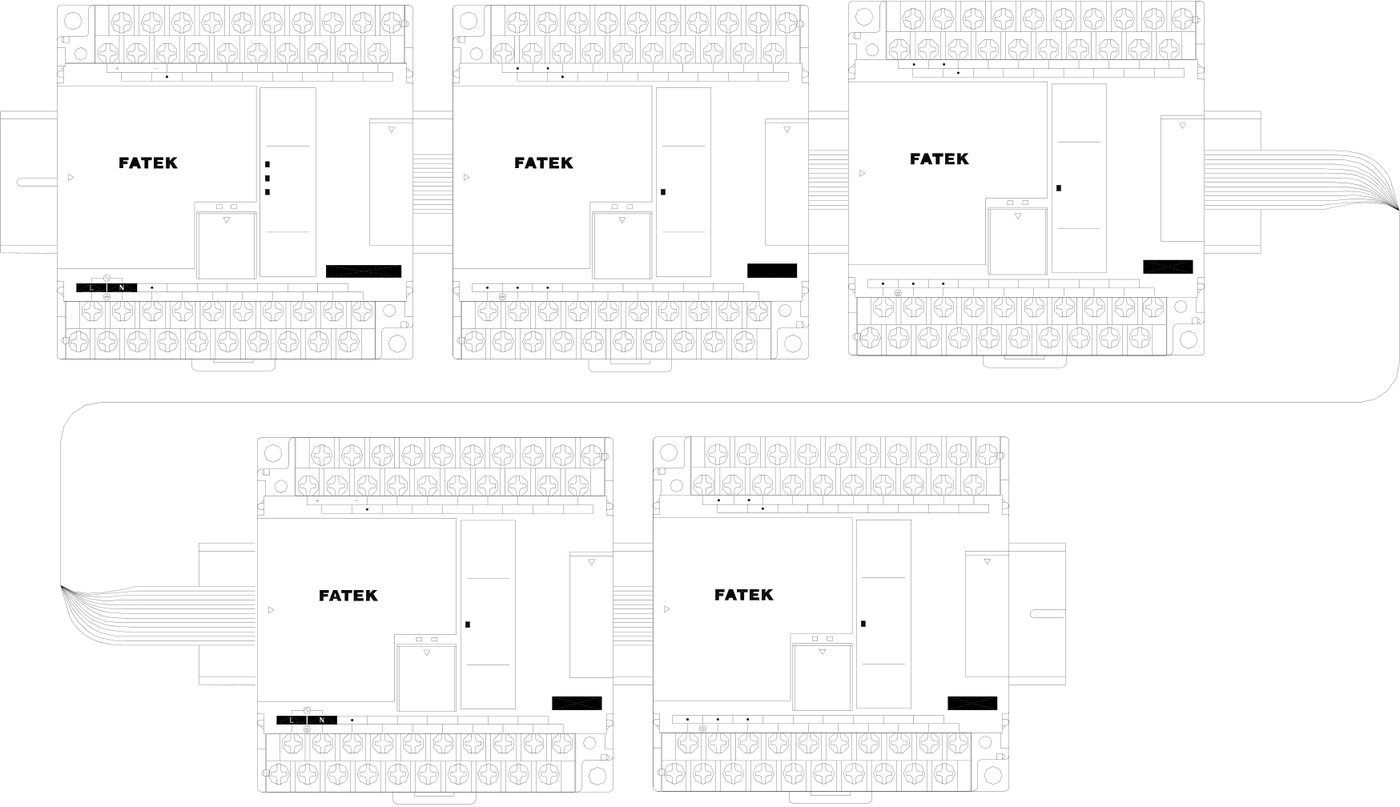
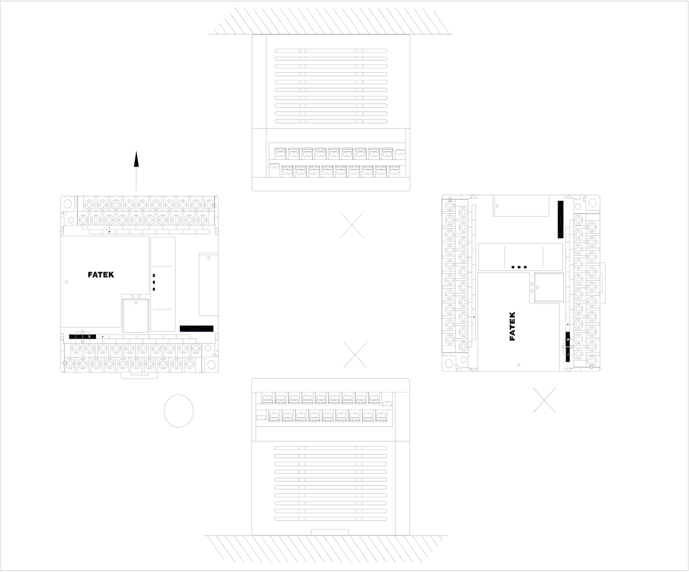
Fixation of FBS-PLC, which can be fixed by DIN RAIL or screws, should place vertically and start from the main unit on the left to the expansion unit on the right. A typical figure of placement is shown below:
|
Suggested arrangement |
max. |
24V OUT |
X0 |
X1 |
X2 |
X4 |
X5 |
X6 |
X8 |
X10 |
X12 |
X3 |
X4 |
X5 |
X6 |
X7 |
X8 |
X9 |
S/S |
X1 |
X2 |
X3 |
X4 |
X5 |
X6 |
X7 |
X9 |
X10 |
X11 |
X13 |
X3 |
X4 |
X5 |
X6 |
X7 |
X8 |
X9 |
S/S |
X1 |
X2 |
X3 |
X4 |
X5 |
X6 |
X7 |
X X8 |
9 |
X11 |
X13 |
||||||||||
|
S/S |
Y1 |
X3 |
RX |
X7 |
X9 |
Y2 |
Y3 |
Y5 |
X8 |
PROGRAMMABLE CONTROLLER |
Y2 |
C3 |
Y3 |
Y4 |
Y5 |
C5 |
0 |
I |
2 |
3 () X () Y 7 |
Y9 |
FBs-24XYR |
|||||||||||||||||||||||||||||||||||||
|
0 |
2 |
3 |
0 |
I 2 |
3 |
||||||||||||||||||||||||||||||||||||||||||||||||||||||
|
4 5 |
5 6 |
7 |
4 |
5 |
6 |
7 |
4 |
5 |
6 |
||||||||||||||||||||||||||||||||||||||||||||||||||
|
8 9 |
9 I0 |
I I |
8 |
9 |
I0 |
I I |
8 |
9 |
I0 |
||||||||||||||||||||||||||||||||||||||||||||||||||
|
PROGRAMMABLE |
I2 I |
3 |
PROGRAMMABLE |
I2 I |
3 |
I2 |
I3 |
||||||||||||||||||||||||||||||||||||||||||||||||||||
|
TX |
INX ( ) |
INX () |
IN ( |
||||||||||||||||||||||||||||||||||||||||||||||||||||||||
|
POW |
|||||||||||||||||||||||||||||||||||||||||||||||||||||||||||
|
IN |
CONTROLLER |
C2 |
C4 |
ERR |
FBs-24MCR2-AC |
CONTROLLER |
C3 |
Y4 |
C5 |
POW |
Y8 |
FBs-24XYR |
POW |
||||||||||||||||||||||||||||||||||||||||||||||
|
OUTY () 0
|
OUTY ()
3 |
OUTY ( 0
|
|||||||||||||||||||||||||||||||||||||||||||||||||||||||||
|
AC100~240V |
PORT0 |
Y4 |
4 5 |
5 6 |
7 |
C1 |
Y1 |
4 |
5 |
6 |
7 |
C1 |
Y1 |
4 |
5 |
6 |
|||||||||||||||||||||||||||||||||||||||||||
|
89 |
8 |
9 |
8 |
9 |
|||||||||||||||||||||||||||||||||||||||||||||||||||||||
|
Y2 |
Y5 |
Y6 |
Y8 |
Y6 |
Y7 |
Y9 |
Y6 |
Y |
Y10 |
||||||||||||||||||||||||||||||||||||||||||||||||||
|
C0 |
Y0 |
Y3 |
C6 |
Y7 |
Y9 |
C7 |
Y10 |
C7 |
|||||||||||||||||||||||||||||||||||||||||||||||||||
|
max. |
24V OUT |
X1 |
X11 |
X13 |
X1 |
X1 |
X13 |
||||||||||||||||||||||||||||||||||||||||||||||||||||
|
400mA |
S/ |
S X2 |
0 |
3 |
X10 |
X12 |
X14 |
S/S |
X2 |
0 |
2 3 |
X10 I |
X12 |
X14 |
|||||||||||||||||||||||||||||||||||||||||||||
|
I |
2 |
I |
|||||||||||||||||||||||||||||||||||||||||||||||||||||||||
|
multiple unit expansion |
4 |
56 |
7 |
4 |
5 |
6 7 |
|||||||||||||||||||||||||||||||||||||||||||||||||||||
|
8 |
9 |
I0 |
I I |
8 |
9 I |
0 I I |
|||||||||||||||||||||||||||||||||||||||||||||||||||||
|
I2 |
I3 |
I2 |
I3 |
||||||||||||||||||||||||||||||||||||||||||||||||||||||||
|
IN |
PROGRAMMABLE |
Y2 |
C3 |
Y3 |
Y4 |
Y5 |
C5 |
INX () |
Y8 |
Y9 |
FBs-24XYR |
PROGRAMMABLE |
Y2 |
C3 |
Y3 |
Y4 |
Y5 |
C5 |
INX () |
Y8 |
Y9 |
FBs-24XYR |
|||||||
|
CONTROLLER |
POW |
CONTROLLER |
POW |
||||||||||||||||||||||||||
|
OUTY () |
OUTY () |
||||||||||||||||||||||||||||
|
0 |
I |
2 |
3 |
0 |
2 |
3 |
|||||||||||||||||||||||
|
4 |
56 |
7 |
4 |
6 |
7 |
||||||||||||||||||||||||
|
8 |
9 |
8 |
|||||||||||||||||||||||||||
|
AC100~240V |
Y6 |
Y7 |
C1 |
Y1 |
Y6 |
Y7 |
|||||||||||||||||||||||
|
C1 |
Y1 |
C7 |
Y10 |
C7 |
Y10 |
||||||||||||||||||||||||
|
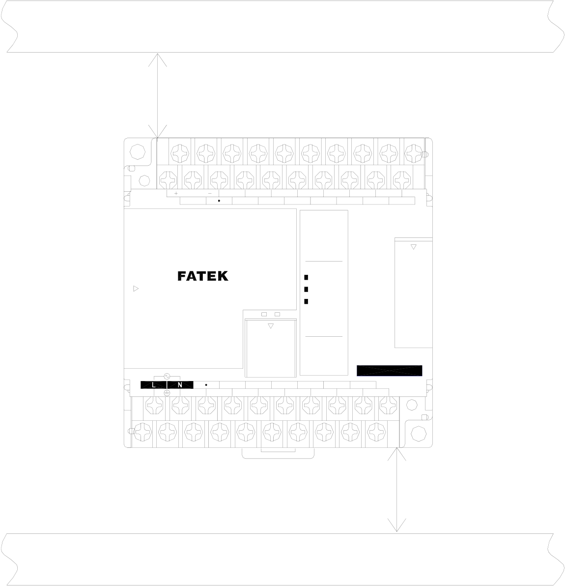
The heat in FBS-PLC is ventilated via air circulation. There should reserve more than 20mm space, both below and
above PLC, and with vertical installation, for ventilation. as shown in the figure below:
Heat ventilation
|
max. |
24V OUT |
X0 |
X2 |
X4 |
X6 |
X |
8 3 |
X10 |
X12 |
Hanged |
X13 |
RX |
() OUTY |
3 |
7 |
FBs-24MCR2-AC |
Y8 |
|||||||||||
|
X12 |
||||||||||||||||||||||||||||
|
X11 |
||||||||||||||||||||||||||||
|
400mA |
S/S |
X1 |
X3 |
X5 I |
X7 |
X11 |
X13 |
X10 |
||||||||||||||||||||
|
0I |
2 |
X9 |
Y7 |
|||||||||||||||||||||||||
|
45 |
6 |
X8 |
3 |
7 |
II |
I3 |
( ) INX |
POW |
RUN |
ERR |
Y6 |
|||||||||||||||||
|
89 I 2I3 |
0 |
6 |
2 I |
56 |
I0 9 |
2 I |
6 5 |
9 |
5 |
|||||||||||||||||||
|
PROGRAMMABLE |
IN ( |
( ) X () Y 3 7 6 Y7 |
FBs-24MCR2-AC |
On floor |
X |
0 |
4 |
8 |
I2 |
0 |
4 |
8 |
Y |
|||||||||||||||
|
POW |
X5 |
C4 |
||||||||||||||||||||||||||
|
X4 |
PORT0 |
Y4 |
||||||||||||||||||||||||||
|
RUN |
||||||||||||||||||||||||||||
|
CONTROLLER |
ERR |
X3 |
TX |
Y |
||||||||||||||||||||||||
|
TX |
RX |
X2 |
Y2 |
|||||||||||||||||||||||||
|
OUT |
X1 |
1 |
||||||||||||||||||||||||||
|
PORT0 |
0 I |
2 |
X0 E |
Y1 |
||||||||||||||||||||||||
|
4 5 |
6 |
24V OUT |
PROGRAMMABLE |
CONTROLLER |
AC100~240V |
Y0 C0 |
||||||||||||||||||||||
|
IN |
AC100~240V |
9 |
||||||||||||||||||||||||||
|
Y1 |
Y2 |
Y4 |
Y5 |
Y8 |
||||||||||||||||||||||||
|
C0 |
Y0 |
C2 |
Y3 |
C4 |
C6 |
Y9 |
||||||||||||||||||||||
|
max. |
||||||||||||||||||||||||||||
|
Vertical with |
4 Horizontal |
IN |
||||||||||||||||||||||||||
|
front facing out |
||||||||||||||||||||||||||||
Wiring slot
Distance ≧50mm
|
max. |
24V OUT |
X0 |
X1 |
X2 |
X3 |
X4 |
X5 |
X |
X8 |
X9 |
X10 |
X11 |
X12 |
X13 |
||
|
400mA |
S/S |
X7 |
||||||||||||||
|
0 |
I |
2 |
3 |
|||||||||||||
|
4 |
5 |
6 |
7 |
|||||||||||||
|
89 |
I0 |
II |
||||||||||||||
|
I2 |
I3 |
|||||||||||||||
INX ( )
POW
|
PROGRAMMABLE |
TX |
RX |
RUN |
|
CONTROLLER |
|||
|
ERR |
OUTY ()
|
IN |
AC100~240V |
Y1 |
C2 |
PORT0 |
Y4 |
C4 |
0 |
I |
2 |
3 |
Y7 |
FBs-24MCR2-AC |
|
|
45 |
6 |
7 |
|||||||||||
|
8 |
9 |
||||||||||||
|
C0 |
Y0 |
Y2 |
Y5 |
Y6 |
Y8 |
||||||||
|
Y3 |
C6 |
Y9 |
|||||||||||
|
Distance ≧ 50mm |
|||||||||||||
Wiring slot


|
4.3 Fix |
ation by DIN RAIL |
|||
|
In an env maintena Mount Dismo |
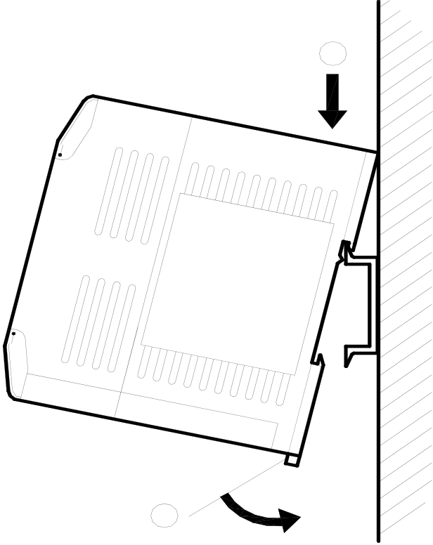
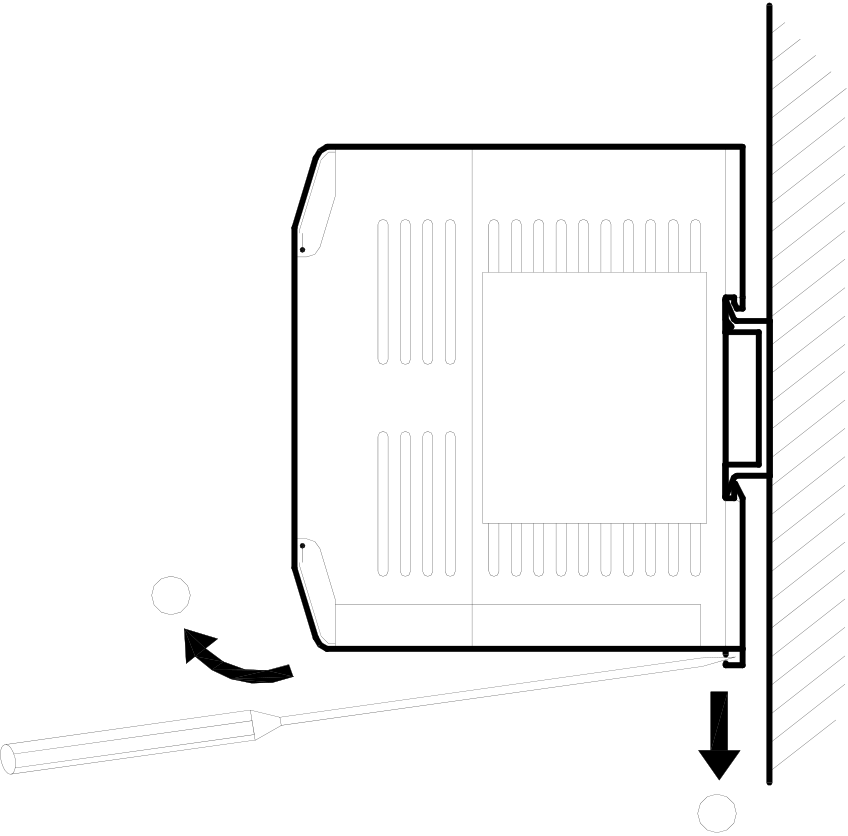
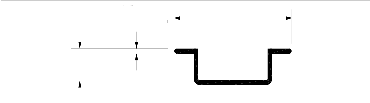
In an env ironment with slight vibration (less than 0.5G), this is the most convenient way of fixation and is easy for maintenance. Please use DIN EN50022 DIN RAIL, as shown in the figure below.
35mm Mount以Hold PLC facing its front, press it down with a 15 degree tilt onto the DIN RAIL. Swing it down until the upper edge of DIN RAIL groove on PLC back touches the upper tab of DIN RAIL. Then use this locked-in point as a pivot to press the PLC forward on the bottom and lock it in position. The procedure is illustrated below: 1 Make sure the tab is pressed in, or
2 Dismount以Use a long screwdriver to reach in the hole on the DIN RAIL tab. Pull out the tab to “pulled out” position to remove PLC, as shown in the figure below. Tab in “pulled out” position
2 1 |
|||








|
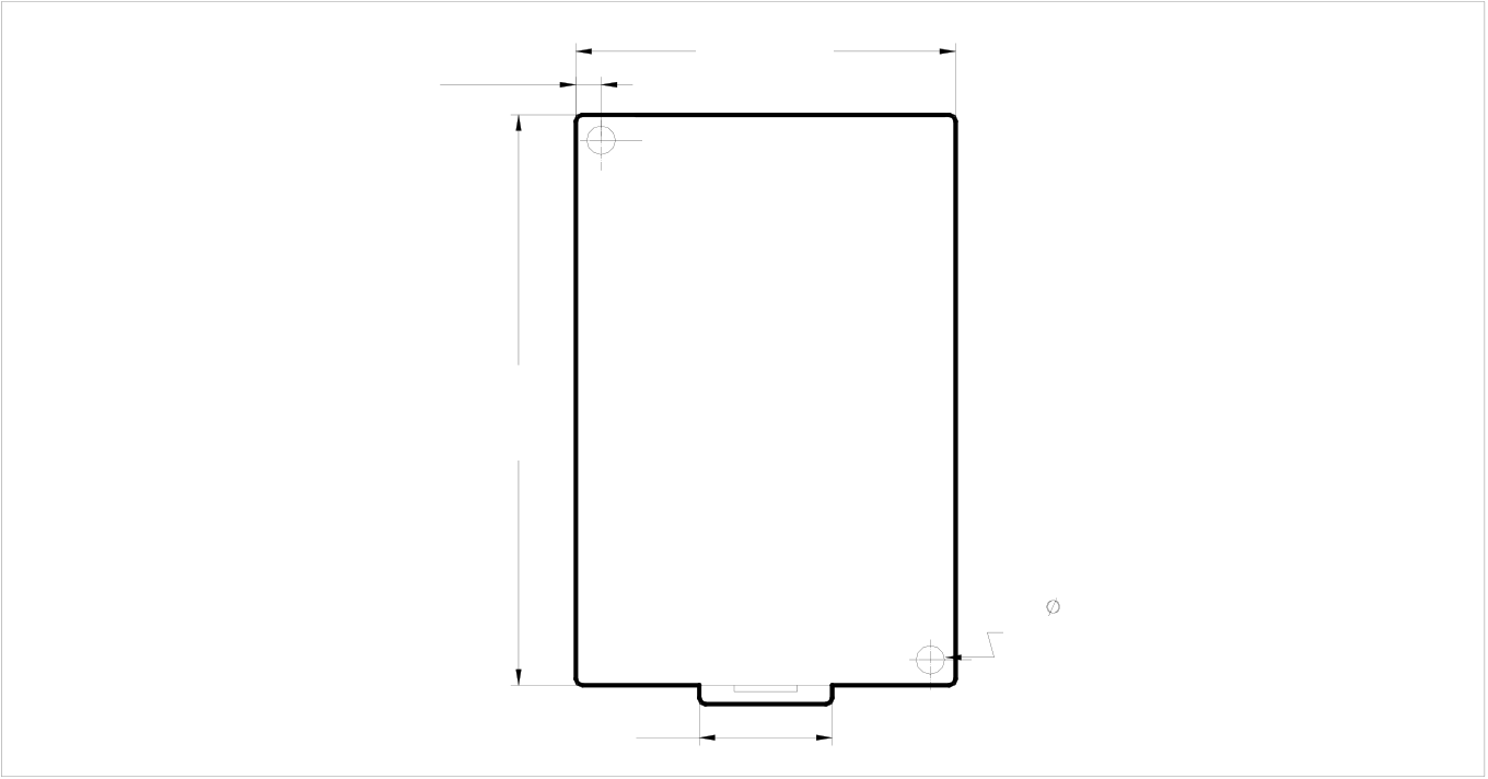
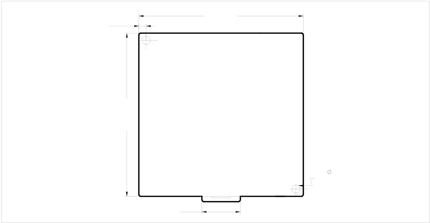
4.4 Fixation by Screws |
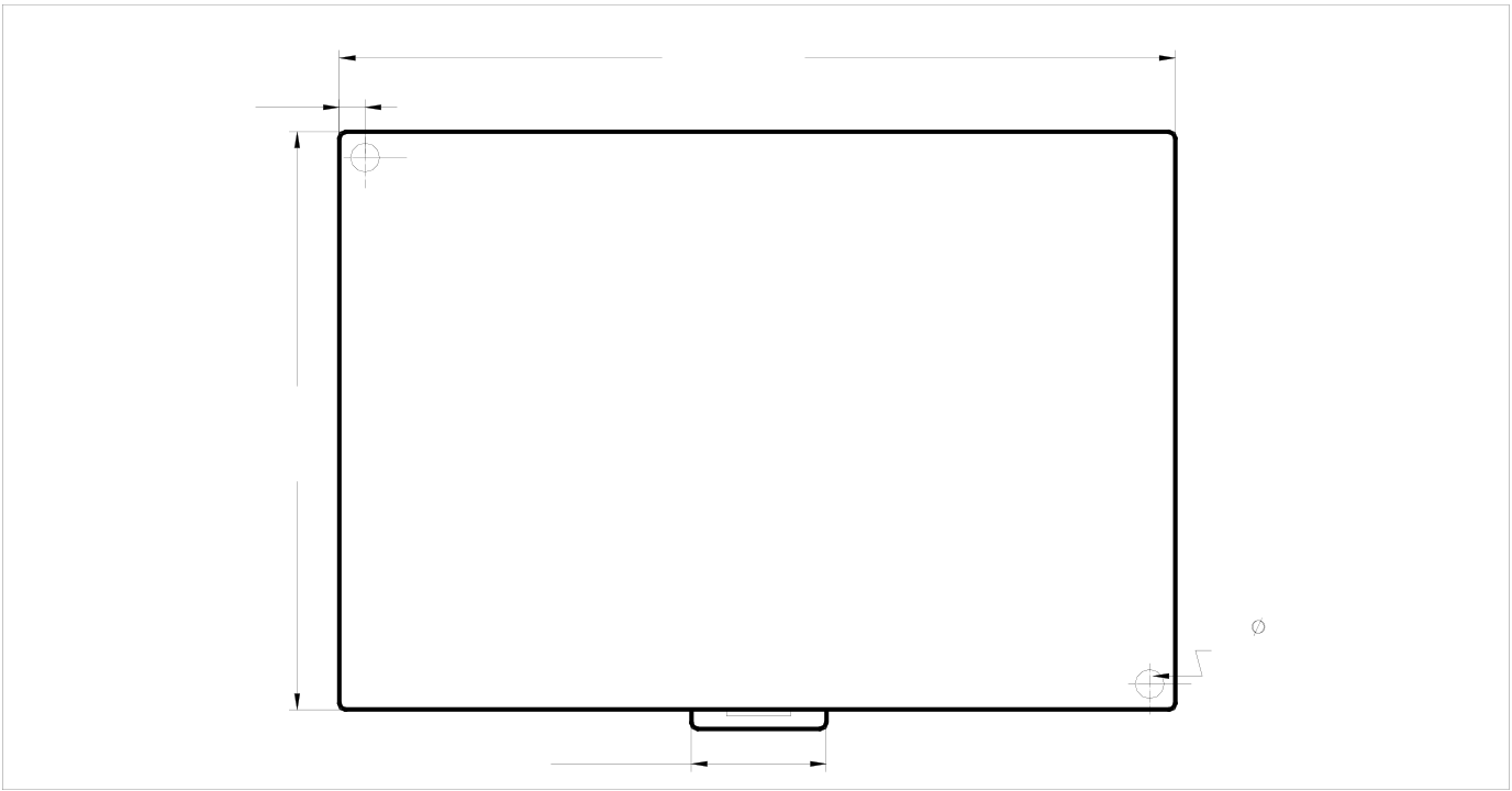
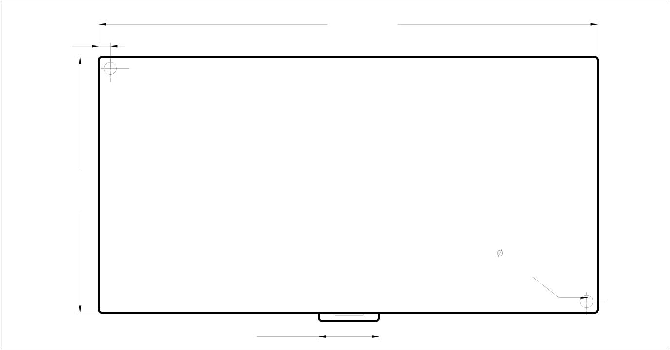
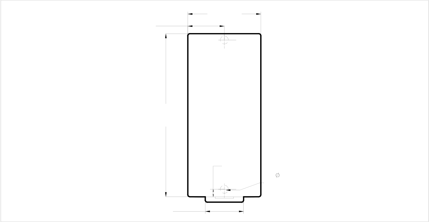
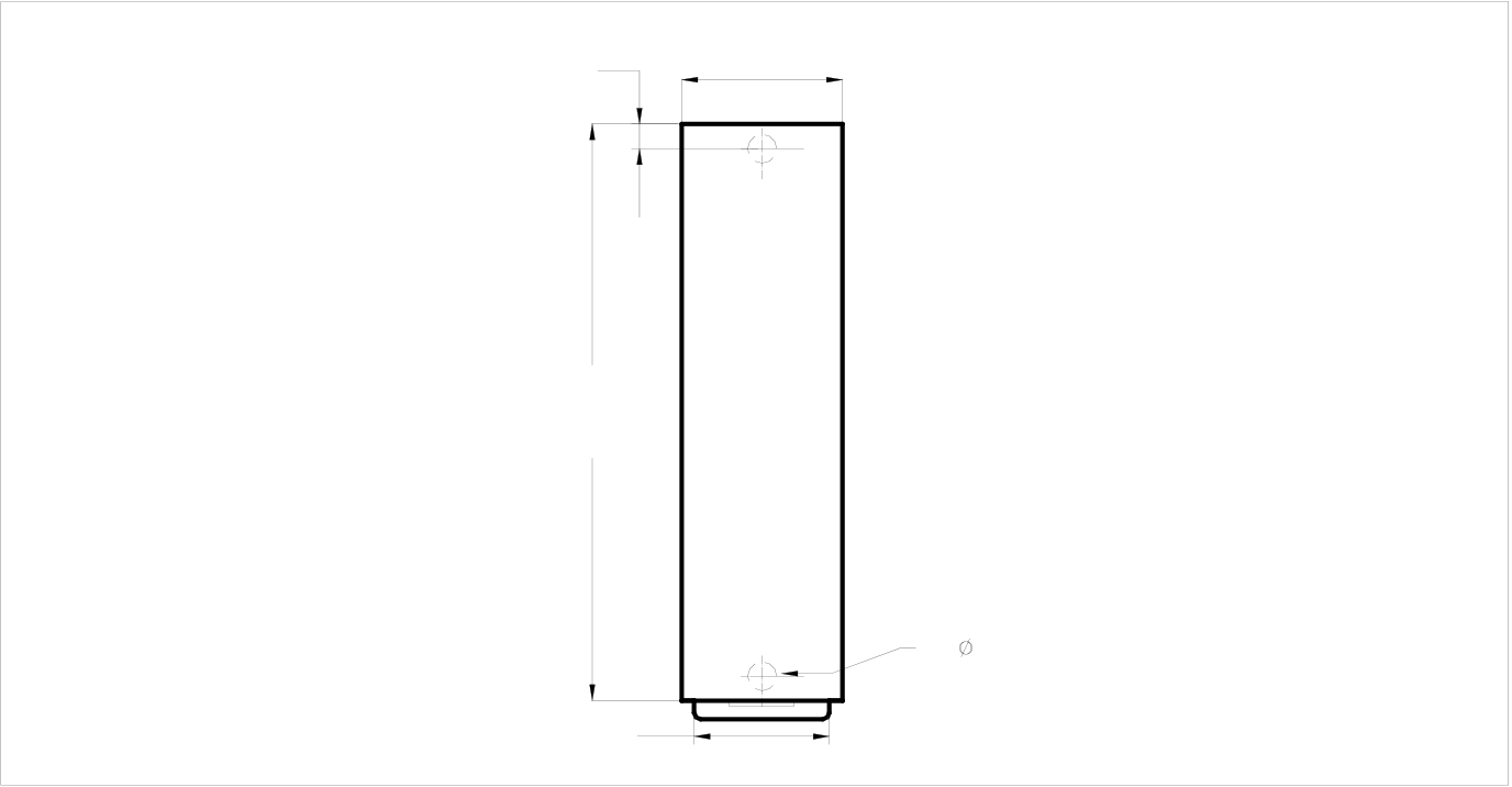
In environments with larger vibration (more than 0.5G), the unit must be secured by M3 or M4 screws. Positions and
sizes of screw holes in various models of FBS-PLC are illustrated in the following:
|
尺寸A : Size A: |
4mm |
60mm |
|
(2.362in) |
||
|
(0.157in) |
90mm
(3.543in)
2 – 4.5mm
(0.177in)
21mm
(0.827in)
|
尺寸B : Size B: |
4mm |
90mm |
|
(0.157in) |
(3.543in) |
90mm
(3.543in)
2 – 4.5mm
(0.177in)
21mm
(0.827in)
|
Size C:尺寸C : |
4mm |
130mm |
|
(5.118in) |
||
|
(0.157in) |
90mm
(3.543in)
2 – 4.5mm
(0.177in)
21mm
(0.827in)
|
Size D:尺寸D : |
4mm |
1750mm |
|
(6.890in) |
(0.157in)
90mm
(3.543in)
2 – 4.5mm
(0.177in)
21mm
(0.827in)
|
尺寸E : Size E: |
20mm |
40mm |
|
(1.575in) |
||
|
(0.787in) |
90mm
(3.543in)
3.8mm
|
(0.150in) |
2 – 4.5mm |
(0.177in)
21mm
(0.827in)
|
尺寸F : Size F: |
3.8mm |
25mm |
|
(0.984in) |
||
|
(0.150in) |
90mm
(3.543in)
2 – 4.5mm
(0.177in)
21mm
(0.827in)

|
4.5 Precautions on Construction and Wiring |
1. During the wiring of FBS–PLC, please follow local national standards or regulations for installation 2. Please choose the wires with proper wire gauge for I/O wiring according to the current loads.
3. Shorter wires are preferred. It is advised that the length of I/O wiring does not exceed 100m (10m for high-speed input).
4. Input wiring should be separated from output or power wiring (at least 30~50mm apart). In case separation is not possible, adopt vertical crossing, no parallel wiring is allow.
5. The pitch of FBS-PLC terminal block is 7.62mm. The torque for screw and suggested terminal is shown below:
|
7.62 mm |
< 6mm |
M3 |
< 6mm |
M3 |
torque: 6~8kg-cm |
|
terminal block |
5.2~6.9 In/lbs |
Tip: press ← → to switch chapters, Ctrl+K to search