If the I/O point of the. Main unit of the applied FBS-PLC is not enough for a specific application, then can expand it with the additional expansion units/modules. Besides I/O point there also have the requirements to expand the communication port in some occasions.
3.1I/O Expansion
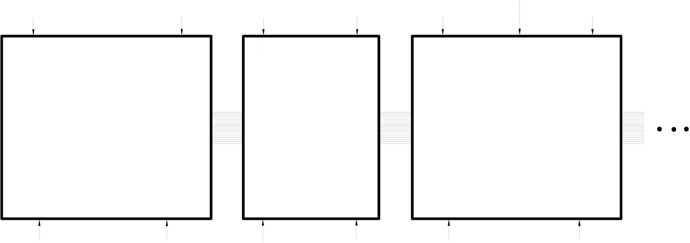
The expansion of FBS-PLC I/O consists of Digital I/O ( DI/O, which status is represented by a single bit) and the Numeric I/O (NI/O , which status is represented by a 16-bit Word). Either the DI/O or the NI/O expansion is realized through expansion units or modules cascaded thru the usage of the “I/O Output Expansion Connector” located at the right side of FBS-PLC or expansion unit/ module.
The I/O points of FBS-PLC system are limited to 512 points of DI/O (256 points for DI and DO, respectively), 128 words of NI/O (64 words for NI and NO, respectively). Besides this there are two limits imposed by hardware: ○1. A maximum number of 32 units or modules can be used in the expansion. ○2. The total length of the expansion cables cannot exceed 5 meters.
|
•Caution |
|
1. If the I/O points of the application system exceed one of the limitations(256 DI,256 DO,64 NI, 64 NO), while startup the main unit of FBS-PLC will treat this as an illegal I/O configuration, which in return will flag as an error situation by turn on the “ERR” LED and put the error code in Y0~Y3 LED(refer the page 8-2, Chapter 8). The corresponding error code will also be indicated in the CPU status register (R4049). 2. The maximum number of expansion units/modules of FBS-PLC is 32. Beyond this numbers will be treated as an invalid I/O configuration and the main unit will stop its operation, which in return will flag as an error situation by turn on the “ERR” LED and put the error code in Y0~Y3 LED(refer the page 8-2, Chapter 8). The corresponding error code will also be indicated in the CPU status register (R4049). |
|
•Warning |
|
1. The maximum length of the I/O expansion cable for FBS-PLC is 5 meters. Cables longer than that will cause incorrect I/O operation because of excess signal delay in hardware or noise pickup, resulting in damage to equipment or posing hazard to operating personnel. Since this kind of situation cannot be detected by the PLC main unit, users are advised to take extra cautions and necessary measures. |
|
3.1.1Digital I/O Expansion and I/O Numbering |
Digital I/O means I/O with the discrete type status, including digital input (with initial X in DI numbering) and digital output (with initial with Y in DO numbering). The DI and DO of FBS-PLC can both be expanded up to 256 points (numbered as X0~X255 and Y0~Y255, each with 256 points).
The status of input contacts (X0~X255) of PLC come from the input signal connected to the digital input terminal block on main unit or expansion unit/module; while the status appears at digital output terminal block of main unit and expansion unit/module reflects the digital output relay (Y0~Y255) status inside PLC.
On FBs-PLC main unit, at the position below the digital input terminal block and the position above the output terminal block, there have labels indicate the corresponding signal name. They label each terminal with numbers representing the corresponding digital input contact Xn and digital output relay Yn. In the example of the main unit in FBS-24MCR, the corresponding digital input contacts on the input terminal block are labeled X0~13, and the corresponding digital output relays on the output terminal block Y0~Y9. Users only need to locate the printed label for each terminal to find out its I/O number. The LED status display region also indicates the ON/OFF status for all DI(X0~X13) and DO(Y0~Y9)
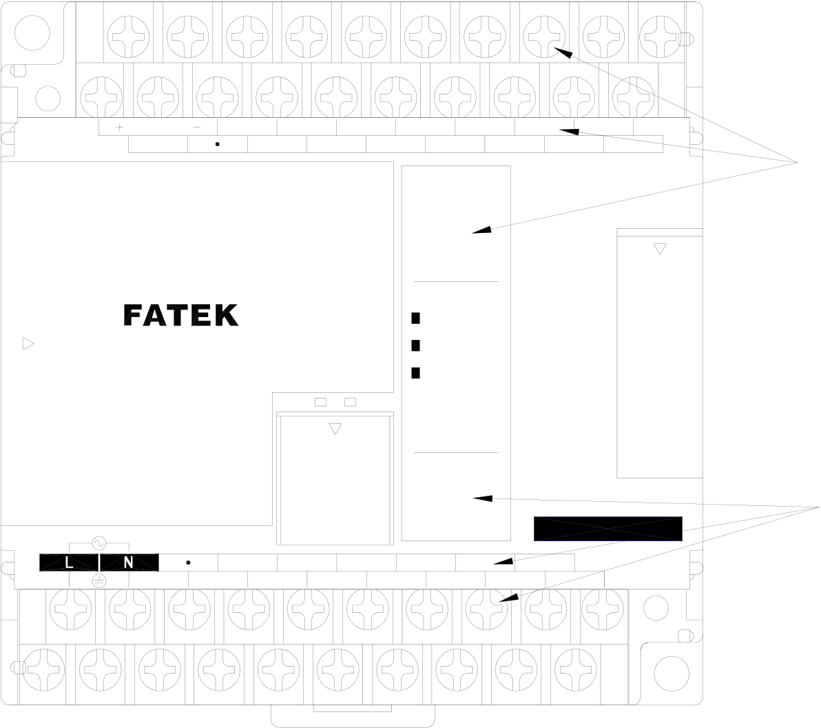
on the main unit. Users can easily find each terminal with its I/O number and LED status indication, as shown in the figure below using X10 and Y6 as an example:
|
max. |
24V OUT |
X0 |
X2 |
X4 |
X6 |
X8 |
X10 |
X12 |
|
400mA |
S/S |
X1 |
X3 |
X5 |
0 |
X7 |
3 |
X9 |
X11 |
X13 |
X10 |
||
|
I |
2 |
||||||||||||
|
4 |
5 |
6 |
7 |
||||||||||
|
8 |
9 |
I0 |
I I |
||||||||||
I2I3
INX ( )
POW
|
PROGRAMMABLE |
TX |
RX |
RUN |
|
CONTROLLER |
ERR |
OUTY ()
|
IN |
AC100~240V |
Y1 |
C2 |
PORT0 |
Y4 |
C4 |
0 |
I |
2 |
3 |
Y7 |
FBs-24MCR2-AC |
Y6 |
||
|
4 |
5 |
6 |
7 |
||||||||||||
|
89 |
|||||||||||||||
|
C0 |
Y0 |
Y2 |
Y5 |
Y6 |
Y8 |
||||||||||
|
Y3 |
C6 |
Y9 |
|||||||||||||
While the various expansion units/modules other than the main units have the same printed labels on the input/output terminals as the main units do, these labels are only relative I/O numbers, different from the absolute I/O numbers on main units. The number of a terminal only represents its order on the expansion unit/module. For example, the first contact is X1 or Y1, the second X2 or Y2, etc. All numbers on the expansion unit/module begin with 1. The actual number of digital input contact or the output replay, however, is determined by summing the numbers on all previous expansion units/modules and the main unit. See the following figure and its calculation.
X49
|
X0 |
X23 |
X24 |
X37 |
X38 |
X61 |
|
X0 X1• • • • • • • • • • • • • • X23 |
X1 X2• • • • • • • • X14 |
X1 X2• • • • • • X12 • • • • • • X24 |
|||
|
FBS-40M△ |
FBS-24XYR |
FBS-40XYR |
|||
|
(主機 ) |
(第1個擴充機/模組 ) 1 st expansion |
(第2個擴充機/模組 ) 2 nd expansion |
|||
|
Y0 Y1• • • • • • • • • • • • Y15 |
unit/module |
unit/module |
|||
|
Y1 Y2• • • • • • • • Y10 |
Y1 Y2• • • • • • • • • • • • Y16 |
||||
|
Y0 |
Y15 |
Y16 |
Y25 |
Y26 |
Y41 |
As shown in the above figure, because the top X numbers of the previous two units are 23 and 14, respectively, the number of input contact X12 on second expansion unit should be:
X(23+14+12) = X49
|
3.1.2Numeric I/O Expansion and I/O Channel Mapping |
The numeric I/O in FBs-PLC treat 16 single-bit data as one 16-bit numeric data (Word) ranging from the 0~65535. Since all numeric data of FBs-PLC are stored in the register inside PLC (16-bit width), therefore numeric I/O is also called register I/O. The Input Register (IR) has 64 Word (R3840 ~ R3903) for inputs from external numeric input (NI) module, and the Output Register (OR) also has 64 Word (R3904 ~ R3967) for outputs to external numeric output (NO) module.
Analog Input Module, Temperature Module, and Thumbwheel switch multiplex input module are of Numeric input (NI) modules which use input register (IR) to convey the status. Analog Output Module, 7 Segments Display Module are of Numeric output (NO) modules which output is directly from the Output register (OR). The Analog Input, Temperature Input, and Analog Output is of analog voltage or current, while the Thumbwheel switch Input or 7 Segments Display Output uses user-friendly BCD number signal. Either the magnitude of voltage or current or the value of BCD number is represented by the 16-bit value of the corresponding register. The corresponding current/voltage signal or BCD value of any IR or OR on the NI/O module is named as a Channel (CH). The channels on the NI module are called numeric input channels (NI channels) and those on NO module numeric output channels (NO channels). The number of IR/OR used by NI and NO channels on each module varies depending on the module type or working mode. The following table lists the numbers of IR and OR used by NI and NO channels on each NI/O module:
|
NI/O |
NI Channel Label |
NO |
Number of IR occupied (Word) |
Number of |
Note |
|
FBs-6AD |
CH0 |
1 |
|||
|
CH1 |
1 |
||||
|
CH2 |
1 |
||||
|
CH3 |
1 |
||||
|
CH4 |
1 |
||||
|
CH5 |
1 |
||||
|
FBs-2DA |
CH0 |
1 |
|||
|
CH1 |
1 |
||||
|
FBs-4DA |
CH0 |
1 |
|||
|
CH1 |
1 |
||||
|
CH2 |
1 |
||||
|
CH3 |
1 |
||||
|
FBs-4A2D |
CH0 |
1 |
|||
|
CH1 |
1 |
||||
|
CH2 |
1 |
||||
|
CH3 |
1 |
||||
|
CH0 |
1 |
||||
|
CH1 |
1 |
||||
|
FBs-B4AD |
VI0(V) |
1 |
The voltage and |
||
|
II0(I) |
|||||
|
VI1(V) |
1 |
||||
|
II1(I) |
|||||
|
VI2(V) |
1 |
||||
|
II2(I) |
|||||
|
VI3(V) |
1 |
||||
|
II3(I) |
|||||
|
FBs-B2DA |
VO0(V) |
1 |
Both voltage and current will be |
||
|
IO0(I) |
|||||
|
VO1(V) |
1 |
||||
|
IO1(I) |
|
FBs-B2A1D |
VI0(V) |
1 |
The voltage and |
|||
|
II0(I) |
||||||
|
VI1(V) |
1 |
|||||
|
II1(I) |
||||||
|
VO0(V) |
1 |
Both voltage and current will be |
||||
|
IO0(I) |
||||||
|
FBs-32DGI |
Unlabeled |
8 |
1 CH only |
|||
|
FBs-7SG1 |
CH0 |
3(D) |
D:decode mode ND:non-decode mode |
|||
|
4(ND) |
||||||
|
FBs-7SG2 |
CH0 |
3(D) |
||||
|
4(ND) |
||||||
|
CH1 |
2(D) |
|||||
|
4(ND) |
||||||
|
FBS-2TC |
CH0 |
1 |
1 CH only |
|||
|
CH1 |
||||||
|
FBs-6TC/6RTD |
CH0~CH5 |
1 |
1 CH only |
|||
|
FBs-16TC/16RTD |
CH0~CH15 |
1 |
1 CH only |
|||
|
FBs-2A4TC |
2A |
CH0 |
1 |
|||
|
CH1 |
1 |
|||||
|
4TC |
CH0 |
2 |
||||
|
CH1 |
||||||
|
CH2 |
||||||
|
CH3 |
||||||
|
FBs-2A4RTD |
2A |
CH0 |
1 |
|||
|
CH1 |
1 |
|||||
|
4TC |
CH0 |
2 |
||||
|
CH1 |
||||||
|
CH2 |
||||||
|
CH3 |
||||||
|
FBs-6NTC |
CH0~CH5 |
1 |
||||
|
FBs-1LC |
CH0 |
1 |
||||
|
FBs-4PT |
CH0 |
1 |
||||
|
CH1 |
1 |
|||||
|
CH2 |
1 |
|||||
|
CH3 |
1 |
|||||
|
1 |
Or unused |
|||||
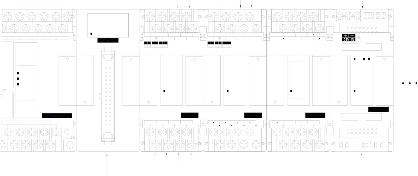
The corresponding IR or OR number calculation of the NI/O module starts from the first expansion unit/module(main unit itself does not have any NI/O). The first NI channel corresponds to the first IR register (R3840). Adding R3840 with the number of IR used by the first NI channel gives the IR number of the second NI channel. Adding the IR number of the second NI channel with the number of IR used by the second NI channel gives the IR number of the third NI channel. All other numbers can be obtained accordingly. Similarly, the first NO channel corresponds to the first OR (R3904). Adding R3904 with the number of OR used by the first NO channel gives the OR number of the second NO channel. (In the cumulative calculation of NI channels, care only for NI channels and disregard DI/O and NI. Similarly, in the case of NO channels, disregard DI/O and NI channels.) The following figure helps users find out the relation between NI/O channels and PLC’s IR and OR.
|
X4 |
X5 |
X6 |
X7 |
X8 |
X9 |
X10 |
X11 |
X12 |
X13 |
POW |
24V IN |
AG |
IR |
24V IN |
AG |
OR |
O1- |
S/S |
X1 |
X2 |
X3 |
X4 |
OR |
|
|
|||||||||||||||||||||||
|
|
O0+ O1+ O0- |
|
|||||||||||||||||||||
|
I0+ I1+ I0-I1- |
|||||||||||||||||||||||
|
FBs-32DGI |



|
0 |
I |
2 |
3 |
V |
I |
U |
B |
5V |
10V |
V |
I |
U |
B |
5V 10V I |
23 |
4 |
CH0 |
V |
|
|
4 |
5 |
6 |
7 |
||||||||||||||||
|
8 |
9 |
I0 |
II |
||||||||||||||||
|
I2 |
I3 |
INX () |
INX () |
EXT |
V |
||||||||||||||
POW
RUN
ERR
|
Y3 |
RX |
C4 |
0 |
OUTY () |
Y7 |
FBs-24MCR2-AC |
POW |
POW |
FBs-2DA |
I |
POW |
POW |
FBs-7SG2 |
||||||
|
OUTY ( ) |
|||||||||||||||||||
|
I |
2 |
3 |
2 |
3 |
4 |
||||||||||||||
|
Y4 |
FBs-6AD |
Y1 |
FBs-8XYR |
CH1 |
|||||||||||||||
|
4 |
5 |
6 |
7 |
||||||||||||||||
|
8 |
9 |
||||||||||||||||||
|
Y5 |
Y6 |
Y8 |
I2+ I3+ I4+ I5+ I2- I3- I4-I5- |
Y2 |
Y3 |
||||||||||||||
|
C6 |
Y9 |
C1 |
C3 |
Y4 |
|||||||||||||||
|
IR |
|||||||||||||||||||
|
IR |
|||||||||||||||||||
OR
During the startup stage, FBs-PLC will automatically detect the types and CH numbers of expansion units/modules. While operation, the FBs-PLC will read the CH input values from the NI module and stores them into corresponding IR(R3804 ~ R3903) and outputs OR values (R3904~R3967) to channels on the NO module. No pre-configuration or setting by users is required.
|
3.2Expansion of Communication Port |
The main unit of FBs-PLC has one built-in communication port (port 0, with optional USB or RS232 interface).
Expansion of communication ports can be achieved by employing Communication Board (CB) or Communication
Module (CM). The available models of CB and CM for FBs are:
|
Model Number |
Specifications |
|
|
FBs-CB2 |
1 RS232 (port2) communication board |
|
|
FBs-CB22 |
2 RS232 (port1 & port2) communication boards |
|
|
FBs-CB5 |
1 RS485 (port2) communication board |
|
|
FBs-CB55 |
2 RS485 (port1 & port2) communication boards |
|
|
FBs-CB25 |
1 RS232 (port1) + 1 RS485 (port2) communication board |
|
|
FBs-CBE |
1 Ethernet communication board |
|
|
FBs-CBCAN |
1 CANopen® communication board |
|
FBs-CM22 |
2 RS232 (port3 & port4) communication modules |
|
|
FBs-CM55 |
2 RS485 (port3 & port4) communication modules |
|
|
FBs-CM25 |
1 RS232 (port3) + 1 RS485 (port4) communication expansion module |
|
|
FBs-CM25E |
1 RS232 (port3) + 1 RS485 (port4) communication module with Ethernet |
|
|
FBs-CM55E |
1 RS485 (port3) + 1 RS485 (port4) communication module with Ethernet |
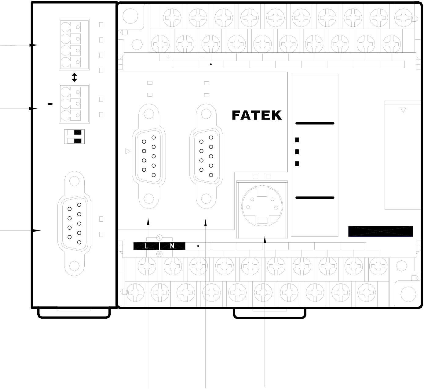
Communication boards, which can be directly installed on FBs main units, are employed for expansion of communication ports port1 and port2. Communication modules are independent modules used for the expansion of communication ports port3 and port4 and need to be mounted against the left side of FBs main unit and connected to the main unit via a 14pin connector. The labels of communication ports are marked on the cover plate of communication boards and modules, from which users can easily identify each port. Except that the built-in communication port (Port0) can only be used for USB or RS 232 interface, all the other ports (Port 1~4) can be used for RS232 or RS 485 interface in CB and CM. The following figure shows an example of expansion of 5 (maximum allowed number) communication ports (CB22+CM25E):
|
The most expansion of communication port diagram |
|
ETHERNET |
3 |
T |
N |
RUN |
max. |
24V OUT |
X0 |
X2 |
X4 |
X5 |
X6 |
X8 |
X9 |
X10 |
X11 |
X12 |
X13 |
||
|
6 |
LNK |
||||||||||||||||||
|
1 |
TX |
||||||||||||||||||
|
(PORT4) |
|||||||||||||||||||
|
2 |
RX |
400mA |
S/S |
X1 |
X3 |
X7 |
|||||||||||||
|
PORT4 |
+ |
TX |
TX |
TX |
PROGRAMMABLE |
0 |
I |
2 |
3 |
||||||||||
|
RX |
RX |
4 |
5 |
6 |
7 |
||||||||||||||
|
RX |
8 |
9 |
I0 |
I I |
|||||||||||||||
|
G |
|||||||||||||||||||
|
I2I3 |
|||||||||||||||||||
|
INX ( ) |
|||||||||||||||||||
|
CONTROLLER |
POW |
||||||||||||||||||
RUN
ERR
TX RX
OUTY ()
|
PORT3 |
TX |
PORT2 |
PORT1 |
Y1 |
C2 |
PORT0 |
C4 |
0 |
I |
2 |
3 |
Y7 |
FBs-24MCR2-AC |
|||
|
4 |
5 |
6 |
7 |
|||||||||||||
|
RX |
8 |
9 |
||||||||||||||
|
IN |
AC100~240V |
Y5 |
C6 |
Y6 |
||||||||||||
|
Y2 |
Y4 |
Y8 |
||||||||||||||
|
C0 |
Y0 |
|||||||||||||||
|
Y3 |
Y9 |
|||||||||||||||
FBs-CM25E
|
PORT2 |
PORT1 |
PORT0 |
Tip: press ← → to switch chapters, Ctrl+K to search