People use ordinary motor to exercise positioning control in early stage; since the speed and precision demand was not so high then, it was enough to fulfill the demand. As the increasing of mechanical operation speed for the efficiency purpose, finished product quality standard, and precision demands are getting higher, the stopping position control of motor is no more what the ordinary motor is capable to do. The best solution for this problem is to adopt NC positioning controller which incorporate with stepping or servo motor to do the position control. In the past, the extremely high cost limited the prevailing of its usage; however, the technology advance and cost decreasing, which made the pricing affordable, had helped to increase the prevailing of usage gradually. To cope with this trend, the FBs-PLC integrated into its internal SoC chip the special NC positioning controller that is available on the market, therefore makes it free from the bothersome data transaction and linking procedure between PLC and special NC positioning controller. Furthermore, it greatly lowered the entire gadget cost hence provides the user the solution for a good bargain, high quality, simple, and convenient integrated NC positioning control with PLC.
11.1 The Methods of NC Positioning
The methods for controlling interface of PLC and stepping or servo driver are as follows:
z Giving command by way of digital I/O: Easy to use but less dexterity in application.
z Giving command by way of analogue output: Better dexterity in controlling reaction but it is with a higher cost and easy to be interfered by noise.
z Giving command by way of communication: There is no standard for communication protocol and it is confined in communication reaction thus constitutes a bottleneck for application.
z Giving command by way of high speed pulse: The cost is low and is easy to precisely controlled.
Of these methods, controlling stepping or servo driver with high speed pulse is more frequently used method. The main unit of PLC contains multi-axis high speed pulse output and hardware high speed counter, and it can provide easy using, designing for positioning program editing. Therefore it makes the related application even more convenient and comfortable.
Following two kinds are frequently used NC server system that constituted by PLC associates with servo drivers:
|
z |
Semi closed loop control |
The PLC is responsible for sending high speed pulse command to servo driver. The motion detector installed on servo motor will forward directly to server driver, closed loop reaches only to server driver and servo motor. The superior point is that the control is simple and the precision is satisfactory (which is suitable for most of the applications). The defect is that it can’t fully reflect the actual shift amount after the transmission element; furthermore, the element being consumed, become aging, or has defect will not be able to be compensated nor checked to verify.
|
z |
Closed loop control |
The PLC is responsible for sending high speed pulse command to servo driver. In addition to that the shift detection signal installed on servo motor which will be forwarded directly to servo driver, the attached shifting detector installed after the transmission element can fully reflect the actual shift amount and forward it to the high speed counter that PLC contains. So as to make the control becomes more delicate, and help to avoid the defect of above mentioned semi closed loop.
11.2 Absolute Coordinate and Relative Coordinate
The designation of moving distance can be assigned by absolute location (absolute coordinate positioning), or assigned by relative distance (relative coordinate positioning). And the DRV instruction is used to drive motor.
While marking the moving distance with absolute coordinate,
if it is located at 100mm at the present, for moving to 300 mm, the positioning instruction is : DRV ABS, ,300 , Ut if it is located at 300mm at the present, for moving to 0mm, the positioning instruction is : DRV ABS, , 0 , Ut.
While marking the moving distance with relative coordinate,
if it is located at 100mm at the present, for moving to 300 mm, the positioning instruction is : DRV ADR, +, 200, Ut. if it is located at 300mm at the present, for moving to 0mm, the positioning instruction is : DRV ADR, −, 300, Ut.


z Absolute coordinate labeling
Program coding for location of 300mm moving to 0mm:

DRVABS,, 0,Ut
|
... |
|
... |
||||||||||
|
-100 |
0 |
100 |
200 |
300 |
||||||||

Program coding for location of 100mm moving to 300mm: DRVABS,,300,Ut
z Relative coordinate labeling
Program coding for location of 300mm moving to 0mm:

DRV ADR,-,300,Ut
|
... |
|
... |
||||||||||
|
-100 |
0 |
100 |
200 |
300 |
||||||||

Program coding for location of 100mm moving to 300mm:
DRV ADR,+,200,Ut
11.3 Procedures of Using FBs-PLC Positioning Control
Start
Configure the high speed pulse output (HSPSO) function under WinProladder or FP-08 configuration function. Switch
the Y0~Y7 output of FBs-PLC to HSPSO circuit in the SoC,
and determine the working mode of output pulse (U/D, PLS/DIR, A/B), and complete the hardware wiring layout between PLC and positioning driver.
——For the wiring layout, please refer to section 11.4.2.
Each axis of motor is controlled by one FUN140 (it can also by
more than one, but only one can be active at any time); then employs the FUN140 extended positioning instruction (SPD,
Please refer to FUN140 and its extended
|
DRV,… etc.) to coding for the needed positioning control |
—— |
positioning instruction for the function and usage |
|
program that will be saved into register block assigned by |
explanation. |
|
|
FUN140 SR operand. Once the FUN 140 input control |
started, it can exercise the positioning controls.
If it needs to do close loop control, it can employ the FBs-PLC hardware high speed counter to count the feedback pulse (e.g. Encoder etc.) after transmission element to achieve.
End
11.4 Explanation for the Positioning Control Hardware of FBs-PLC
11.4.1 Structure of Output Circuit of HSPSO
According to different main unit, it provides different frequency of output pulse, it includes 20KHz (Medium speed) of single ended transistor output model (FBS-xxMCT), and high speed differential output model (FBS-xxMNT) which can reach 920KHz (for single phase), two series of models.
High speed pulse output circuit share to use the Y0~Y7 exterior output of FBs-PLC. While it is not yet using the HSPSO function (haven’t configured the PSO function under configuration function), the Y0~Y7 exterior output of FBs-PLC is corresponding to the Y0~Y7 status of internal output relay. When the HSPSO has been configured, the Y0~Y7 exterior output will switch directly to HSPSO output circuit within SoC, which has no relation with Y0~Y7 relay inside PLC.
The following is the detailed signals list for respective axis output of main unit and the selectable output modes:
|
Axis No. |
Exterior output |
Output modes |
|||
|
U/D output |
P/R output |
A/B output |
Single PLS output |
||
|
PSO0 |
Y0 , Y1 |
Y0=U , Y1=D |
Y0=P , Y1=R |
Y0=A , Y1=B |
Y0=PLS |
|
PSO1 |
Y2 , Y3 |
Y2=U , Y3=D |
Y2=P , Y3=R |
Y2=A , Y3=B |
Y2=PLS |
|
PSO2 |
Y4 , Y5 |
Y4=U , Y5=D |
Y4=P , Y5=R |
Y4=A , Y5=B |
Y4=PLS |
|
PSO3 |
Y6 , Y7 |
Y6=U , Y7=D |
Y6=P , Y7=R |
Y6=A , Y7=B |
Y6=PLS |
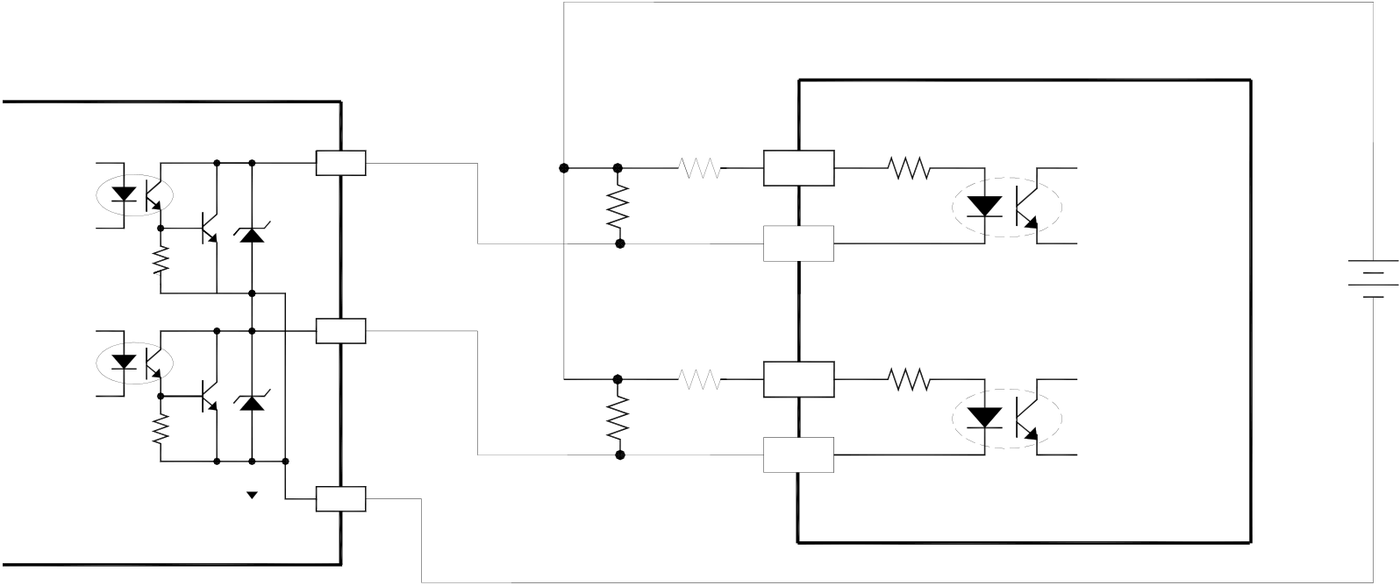
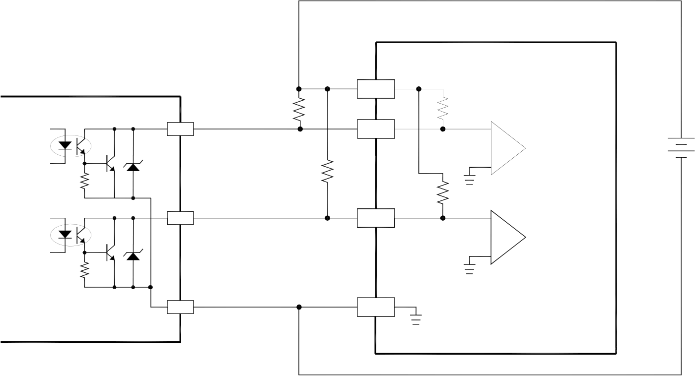
11.4.2 Hardware Wiring Layout for FBs-PLC Positioning Control
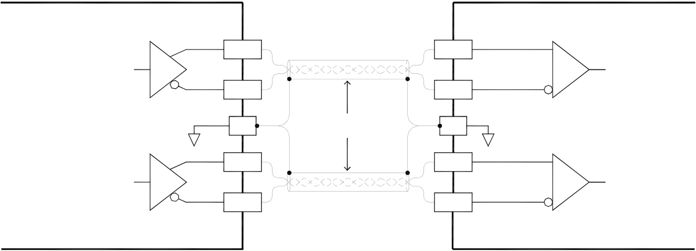
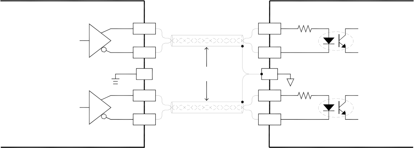
Take the 0th axis (PSO0) of FBs-XXMCT, FBs-XXMAT, and FBs-XXMNR(T) main unit for example, it is illustrated with diagrams as follows; the others are the same.
|
A, FBS-XXMCT , FBs-XXMAT single ended output wiring layout. |
|||||||||||||||||||||||
5~24V DC
C0 * Please refer to Hardware manual H7-6 for the usage of speed-up resistor “R”. |
|||||||||||||||||||||||
Driver (OP input)
|
FBs main unit |
Y0 |
*R |
*R |
Va |
A phase |
+ |
|
A |
||||||
|
5~24V DC |
||||||
|
(or U or PLS) |
||||||
|
Y1 |
B |
B phase |
External power supply |
(or D or DIR)
|
C0 |
C |
|
B、FBS-XXMNR(T) differential output wiring layout |
|
FBS-XXMN PLC |
Y0+ |
Twisted pair |
Driver (Photocouple input) |
|
A+ |
|||
|
Y0 |
Y0- |
A phase(or U or PLS) |
|
|
A- |
|||
|
Y1 |
SG |
FG |
|
|
Y1+ |
B+ |
||
|
B phase(or D or DIR) |
|||
|
FBS-XXMN PLC |
Y1- |
B- |
|
|
Driver (Line receiver input) |
|
Y0 |
Y0+ |
Twisted pair |
A+ |
A phase(or U or PLS) |
|
Y1 |
Y0- |
A- |
B phase(or D or DIR) |
|
|
SG |
FG |
|||
|
Y1+ |
B+ |
|||
|
Y1- |
B- |
(For line receiver input, it must make PLC connect to FG of driver to eliminate common mode voltage)
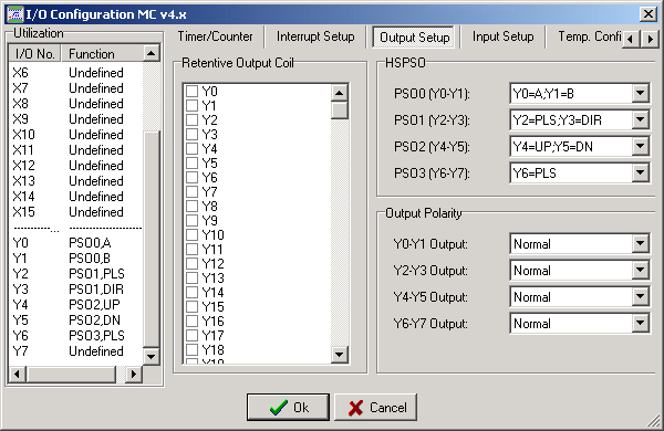
Configuration of HSPSO with WinProladder
Click the “I/O Configuration” Item which in project windows :
|
Project name
I/O Configuration Æ select “Output Setup” |
When “Output Setup” windows appear, then you can configure the Output type :
11.5 The Explanation for the Position Control Function of FBs-PLC
The position control function of FBs-PLC incorporates the dedicated NC position controller, which is available in the market, into the PLC. This makes the PLC and NC controller be able to share the same data block without the demand of complicated works like data exchange and synchronized controlling between these two systems. And it can still use the usual NC positioning control instruction (e.g. SPD , DRV,… etc.).
One main unit can control up to 4 axes of their position control, and can drive multi axis simultaneously. However, it provides point to point positioning and speed control, but also it provides the linear interpolation function. When the system is applying for more than 4 axes, it can also employ CPU LINK function of FBs-PLC to attain control over more positioning actions.
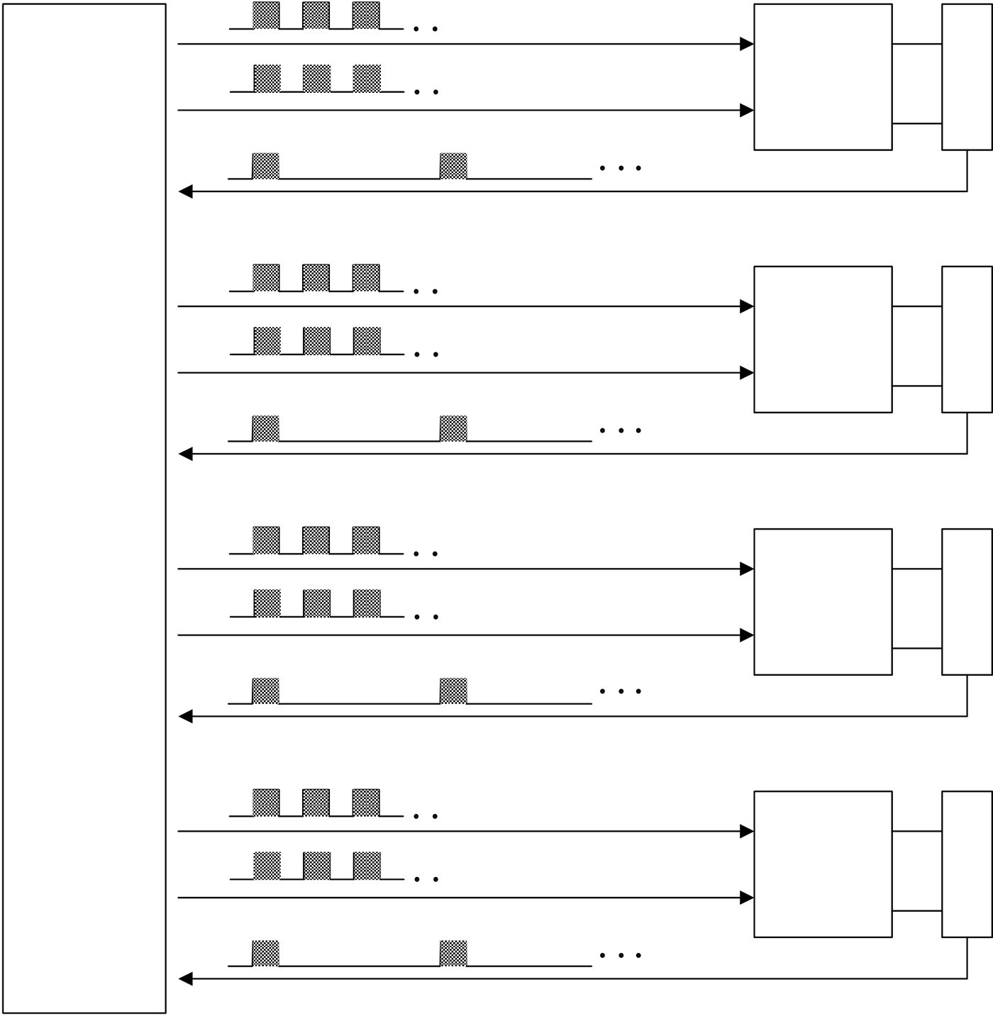
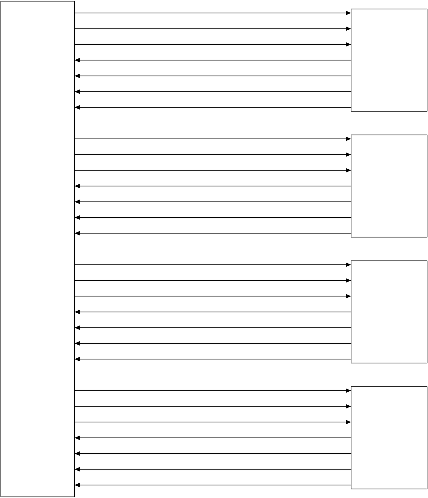
The NC position control instruction for FBs-XXMCT、FBs-XXMN main units are identical to each other. The difference is only on the different circuit output, as previously revealed. Hereby we assume that FBs-XXMCT main unit is used in the control of stepping motor or server with lower speed, and FBs-XXMN main unit is used in high speed servo motor control. Consequently, we illustrate only with the connecting diagram of FBs-XXMCT main unit that driving stepping motor and the diagram of FBs-XXMN main unit that driving servo motor. Of course we can also use FBs-XXMCT main unit to drive servo motor or use FBs-XXMN main unit to drive stepping motor instead, they can still work perfectly, as long as its circuit structure (single ended or differential) and frequency can match.








































11.5.1 Interface of Stepping Motor
|
|
|
|






z Stepping motor is designed to receive input pulse to attain to the control of desired angle or distance, therefore the turning angle and the input pulse count has a positive correlation ship, and the turning speed also depends on the input pulse frequency.
N : Revolving speed of motor (RPM)
|
N (RPM) = 60 × f / n |
f |
: Pulse frequency (PLS/Sec) |
n : Pulse counts for motor to turn for a revolution (PLS/ Rev). n = 360 / θs θs : Angle (Deg)
|
Phase |
Basic |
FULL |
HALF |
||
|
Pulse angle |
Pulse counts for |
Pulse angle |
Pulse counts for |
||
|
5 phase |
0.36° |
0.36° |
1000 |
0.18° |
2000 |
|
0.72° |
0.72° |
500 |
0.36° |
1000 |
|
|
4 phase |
0.90° |
0.90° |
400 |
0.45° |
800 |
|
2 phase |
1.80° |
1.80° |
200 |
0.90° |
400 |









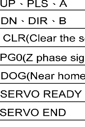
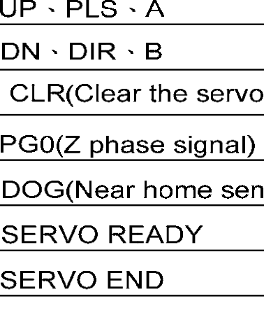
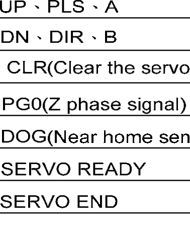
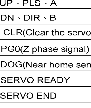


























11.5.2 Interface of Servo Motor
|
|
|
|




※ Except that the Y0~Y7 of above diagram are for dedicated purpose, Y8~Y11 and respective inputs can be adjusted for using according to demand.
※ The left over travel, right over travel limit switches for safety detection also need to be connected to PLC to assure proper operation.
















11.5.3 Working Diagram Illustration for Servo Motor


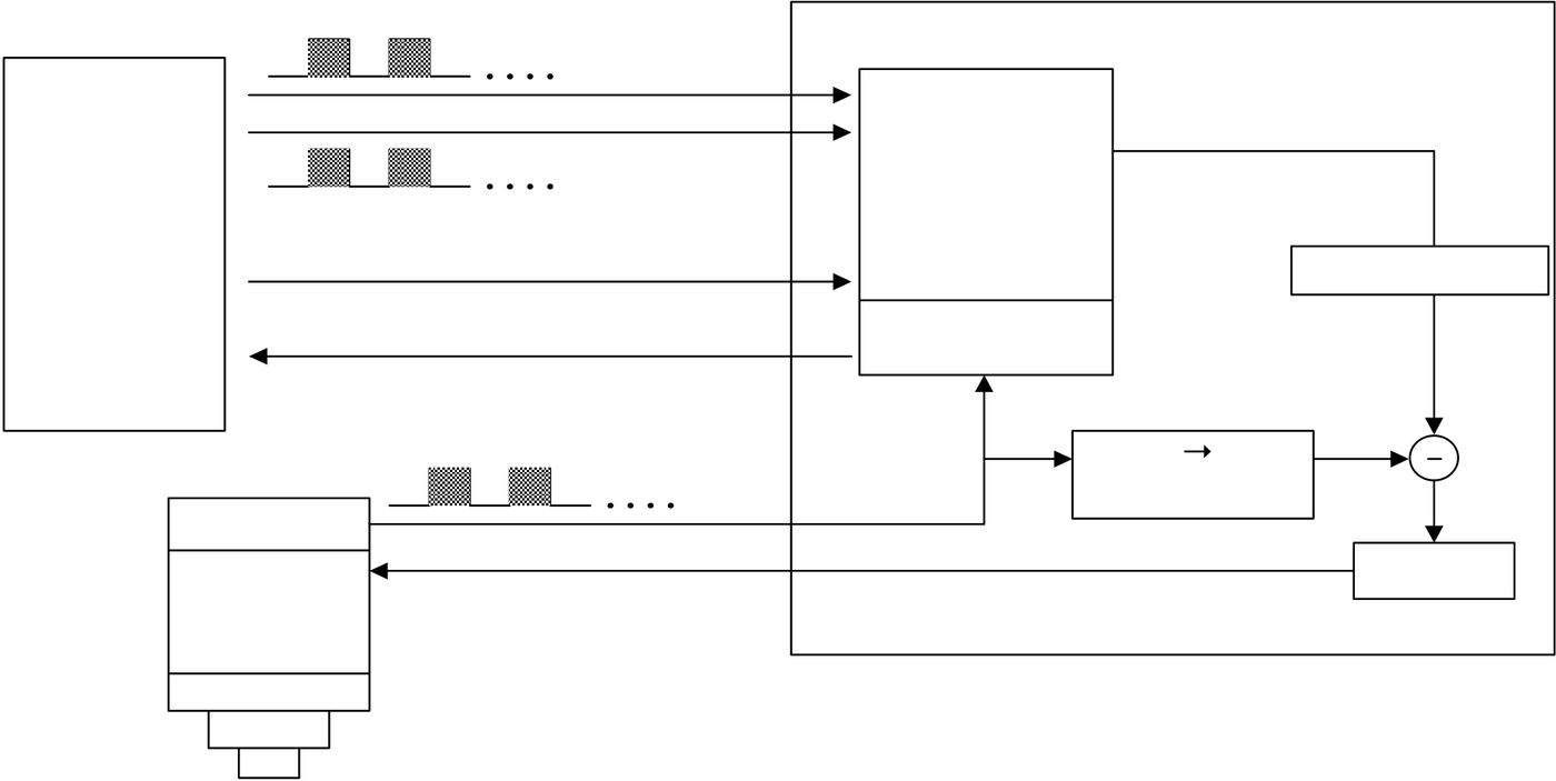
z The Encoder of servo motor feedback the shifting detection signal to servo driver. The driver gets the pulse frequency, and pulse count of input signal (pulse command), as well as the frequency and pulse count of feedback signal processed with internal error counter and frequency to voltage conversion circuit, and acquired the pulse and turning speed deviations. Using these operations to control the servo motor, so as to obtain a high speed, precise speed and positional closed-loop processing system.
z The revolving speed of servo motor depends on the pulse frequency of input signal; the turning stroke of motor is determined by pulse count.
|
z |
Generally speaking, the final control error deviation of servo motor is ±1 pulse. |
11.6 Explanation of Function for NC Position Control Instruction
The NC position control of FBs-PLC has following four related instructions:
z FUN140 (HSPSO) high speed pulse output instruction, which includes following 9 extension positioning instructions:
2. DRV 5. WAIT 3. DRVC 6. ACT 8. GOTO 9. MEND  stored to SR operand area of FUN140 1. SPD 4. DRVZ 7. EXT Used for positioning program coding and
z FUN141 (MPARA) positioning parameter setting instruction
z FUN142 (PSOFF) enforcing pulse output stop instruction.
z FUN143 (PSCNV) converting the current pulse value to displaying value instruction.
z FUN147(MHSPO)multi high speed pulse output instruction, which includes following 7 extension positioning instructions:
2. LIN 5. EXT 3. LINE 6. GOTO  to SR operand area of FUN147
1. SPD 4. WAIT 7. MEND Used for positioning program coding and stored
The following function explanations are for the above mentioned 5 instructions:






NC Positioning Control Instruction
|
FUN 140 HSPSO |
High Speed Pulse Output |
FUN 140 HSPSO |
|||||||||||||||||||||||||||||||||||||||||||||||||||||||||||||||||||||||||||||||||||||||||||||||||||||||||
|
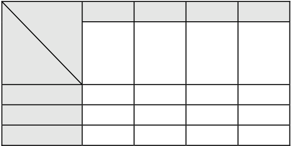
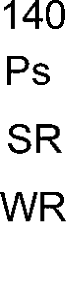
Ps: The set number of Pulse Output (0~3)
|
|||||||||||||||||||||||||||||||||||||||||||||||||||||||||||||||||||||||||||||||||||||||||||||||||||||||||||
|
Instruction Explanation 1. The NC positioning program of FUN140 (HSPSO) instruction is a program written and edited with text programming. We named every position point as a step (which includes output frequency, traveling distance, and transfer conditions). For one FUN140, it can be arranged with 250 steps of positioning points at the most, with every step of positioning point controlled by 9 registers. 2. The best benefit to store the positioning program into the registers is that in the case of association with MMI (Man Machine Interface) to operate settings, it may save and reload the positioning program via MMI when replacing the molds. 3. When execution control “EN”=1, if the other FUN140 instructions to control Ps0 ~3 are not active (corresponding status of Ps0=M1992, Ps1=M1993, Ps2=M1994, and Ps3=M1995 will be ON), it will start to execute from the next step of positioning point (when goes to the last step, it will be restarted from the first step to perform); if Ps0~3 is controlled by other FUN140 instruction (corresponding status of Ps0=M1992, Ps1=M1993, Ps2=M1994, and Ps3=M1995 would be OFF), this instruction will acquire the pulse output right of positioning control once the controlling FUN140 has released the control right. 4. When execution control input “EN” =0, it stops the pulse output immediately. 5. When output pause “PAU” =1 and execution control “EN” was 1 beforehand, it will pause the pulse output. When output pause “PAU” =0 and execution control is still 1, it will continue the unfinished pulse output. 6. When output abort “ABT”=1, it stops pulse output immediately. (When the execution control input “EN” becomes 1 next time, it will restart from the first step of positioning point to execute.) 7. While the pulse is in output transmitting, the output indication “ACT” is ON. 8. When there is execution error, the output indication “ERR” will be ON. (The error code is stored in the error code register.) 9. When each step of positioning point is complete, the output indication “DN” will be ON. |
|||||||||||||||||||||||||||||||||||||||||||||||||||||||||||||||||||||||||||||||||||||||||||||||||||||||||||










NC Positioning Control Instruction
|
FUN 140 HSPSO |
High Speed Pulse Output |
FUN 140 HSPSO |
||||||||||||||||||||||||||||||||||||||||||||||||
|
*** The working mode of Pulse Output must be set (without setting, Y0~Y7 will be treated as general output) to be one of U/D, P/R, or A/B mode, thus the Pulse Output may have a regular output. U/D Mode : Y0 (Y2, Y4, Y6), it sends out upward counting pulse. Y1 (Y3, Y5, Y7), it sends out downward counting pulse. P/R Mode : Y0 (Y2, Y4, Y6), it sends the pulse out. Y1 (Y3, Y5, Y7), it sends out the directional signal; ON=upward counting, OFF= downward counting. A/B Mode : Y0 (Y2, Y4, Y6), it sends out the phase A pulse. Y1 (Y3, Y5, Y7), it sends out the phase B pulse. ● The output polarity for Pulse Output can select to be Normal ON or Normal OFF. [The interfaces for positioning control]
M2000 : ON, multi axes acting simultaneously (At the same scan, when execution control “EN”= 1of FUN140 instructions which control Ps0~3, their pulses output will be sent at the same time without any time lag). : OFF, as the FUN140 for Ps0~3 starts, corresponding axis pulse output will be sent immediately; since the ladder program is executed in sequence, therefore even the FUN140 for Ps0~3 started at the same scan, there must be some time lag between them.
※ R4056 : When the value of low byte=5AH, it can be dynamically changed for its output frequency during the high speed pulse output transmitting at any time. When the value of low byte is not 5AH, it can not be dynamically changed for its output frequency during the high speed pulse output transmitting. The default value of R4056 is 0 |
||||||||||||||||||||||||||||||||||||||||||||||||||
NC Positioning Control Instruction
|
FUN 140 |
High Speed Pulse Output |
FUN 140 |
|
HSPSO |
(Including the extended positioning instruction) |
HSPSO |
R4064 : The step number (positioning point) which has been completed of Ps0. R4065 : The step number (positioning point) which has been completed of Ps1. R4066 : The step number (positioning point) which has been completed of Ps2. R4067 : The step number (positioning point) which has been completed of Ps3.
z Format of positioning program:
SR: Starting register of registers block which reserved to store positioning program, explained as follows:
|
SR |
A55AH |
The effective positioning program; its starting register must be A55AH |
|
1~250 |
||
|
SR+1 |
Total steps |
SR+2
SR+3
SR+4
SR+5
SR+6 The first positioning point (step) of positioning program SR+7 (every step controlled by 9 registers).
SR+8
SR+9
SR+10
The Nth step of positioning program.
SR+N×9+2
NC Positioning Control Instruction
|
FUN 140 HSPSO |
High Speed Pulse Output |
FUN 140 HSPSO |
|||||||||
|
z Explanation for working register of instruction operation: WR is the starting register.
WR+0 : If this instruction is in execution, the content of this register represents the step (1~N) being performed. if this instruction is not in execution, the content of this register represents the step where it stopped at present Before starting the execution control “EN” =1, the user can renew the content of WR+0 to determine starting from which step to perform (when the content of WR+0 =0, and execution control “EN” =1, it represents that the execution starts from the first step). WR+1 : B0~B7, total steps B8 = ON, output paused B9 = ON, waiting for transfer condition B10 = ON, endless output (the stroke operand of DRV command is set to be 0 ) B12 = ON, pulse output transmitting (the status of output indicator “ACT”) B13 = ON, instruction execution error (the status of output indicator “ERR”) B14 = ON, finished being executed step (the status of output indicator “DN”) *** When step which has been completed, the output indication “DN” will turn ON and keep such status if suspending ; the user may turn OFF the status of “DN” by using the rising edge of output coil controlled by "DN" to clear the content of WR+1 register to be 0, and it can be attained. |
|||||||||||
NC Positioning Control Instruction
|
FUN 140 |
High Speed Pulse Output |
FUN 140 |
|
HSPSO |
(Including the extended positioning instruction) |
HSPSO |
|
Error indication |
Error code |
|
|
0 : Error free |
||
|
R4060(Ps0) |
||
|
R4061(Ps1) |
1 : Parameter 0 error |
|
|
R4062(Ps2) |
2 : Parameter 1 error |
|
|
R4063(Ps3) |
3 : Parameter 2 error |
4 : Parameter 3 error
5 : Parameter 4 error
6 Parameter 5 error
7 : Parameter 6 error
8 : Parameter 7 error
9 : Parameter 8 error
10 : Parameter 9 error
The possible error codes for FUN141 execution
13 Parameter 12 error
15 Parameter 14 error
30 : Error of variable address for speed setting
31 : Error of setting value for speed setting
32 : Error of variable address for stroke setting
33 : Error of setting value for stroke setting
34 : Illegal positioning program
35 : Length error of total step
36 : Over the maximum step
37 : Limited frequency error
The possible error codes for FUN140 execution
38 : Initiate/stop frequency error
39 : Over range of compensation value for movement
40 : Over range of moving stroke
41 : ABS positioning is not allowed within DRVC commands 42 : DRVC instruction not allow ABS addressing
50 : Illegal operation mode of DRVZ
51 : Illegal DOG input number
52 : Illegal PG0 input number
53 : Illegal CLR output number
60 : Illegal linear interpolation command
Note : The content of error indication register will keep the latest error code. Making sure that no more error to happen, you can clear the content of error indication register to be 0; as long as the content maintains at 0, it represents that there’s no error happened.
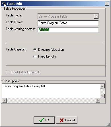
Editing Servo Program Table with WinProladder
Click the “Servo Program Table” Item which in project windows :
Project name
Table Edit
Servo Program Table Æ Click right button and select “New Table”
NC Positioning Control Instruction
|
FUN 140 HSPSO |
High Speed Pulse Output |
FUN 140 HSPSO |
|
● Table Type : It will be fixed to ” Servo Program Table ”. ● Table Name : For modify or debug, you can give a convenient name. ● Table Starting address : Enter the address which Starting register of Servo Program Table.
|
||
NC Positioning Control Instruction
|
FUN 140 HSPSO |
High Speed Pulse Output |
FUN 140 HSPSO |
|||||||||||
|
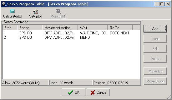
z For easy programming and trouble shooting, the WinProladder provides the text editing environment to edit the motion program(servo program table) for FUN140 execution; Key in the complete FUN140 instruction first and then move the cursor to the position of it, pressing the hot key ”Z”, then comes the text editing environment. The user can create the new motion program or display the existed program under this friendly user interface operation. z Extended positioning instructions are listed as follows:
|
|||||||||||||
NC Positioning Control Instruction
|
FUN 140 HSPSO Instruction DRVC |
High Speed Pulse Output |
FUN 140 |
|
|
(Including the extended positioning instruction) |
HSPSO |
||
|
Operand |
Explanation |
||
|
ADR,+,XXXXXXXX,Ut or or or or ABS,−, Rxxxx ,Ps or |
The usage of DRVC and the operand explanation is the same as DRV’s instruction. *** DRVC is used to do successive speed changing control (8 speeds at the most). |
||
|
Dxxxx |
*** Of the successive speed changing control, only the first DRVC |
||
|
instruction can use the absolute value coordinate for positioning. |
|||
*** The revolution direction of DRVC can only be decided by ‘+’ or ‘−’. *** The revolution direction only determined by the first DRVC of successive DRVC instructions; i.e. the successive speed changing control can only be the same direction.
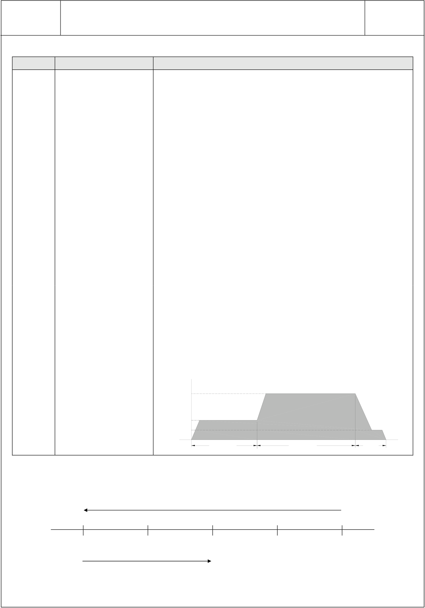
For example: successive 3 speed changing control
|
001 SPD10000 |
* Pulse frequency = 10KHz. * Forward 20000 units. * Pulse frequency =50 KHz * Forward 60000 units. * Pulse frequency = 3KHz. * Forward 5000 units. * Wait until X0 ON to restart from the first step to execute. |
Note: The number of DRVC instructions must be the number of successive speeds deducted by 1, i.e. the successive speed changing control must be ended with the DRV instruction.
y The above mentioned example is for successive 3 speeds changing control, which used 2 DRVC instructions and the third must use DRV instruction.
y Diagram illustration for the above mentioned example:
f
|
50000 |
f1 |
f2 |
f3 |
Ut |
|
10000 |
||||
|
3000 |
20000 |
60000 |
||
|
5000 |
Note: Comparison explanation between the relative coordinate positioning (ADR) and the absolute coordinate positioning (ABS)
To move from position 30000 to −10000, the coding for programming is:
DRV ADR,−,40000,Ut or DRV ABS, ,−10000,Ut
|
... |
-10000 |
0 |
10000 |
20000 |
30000 |
... |
|
Ut |
To move from position −10000 to 10000, the coding for programming is: DRV ADR,+,20000,Ut or DRV ABS,,10000,Ut
NC Positioning Control Instruction
|
FUN 140 HSPSO |
High Speed Pulse Output |
FUN 140 HSPSO |
||||||||||||||||||
|
||||||||||||||||||||
NC Positioning Control Instruction
|
FUN 140 HSPSO |
High Speed Pulse Output |
FUN 140 HSPSO |
|
z The coding for positioning programming : First, it must complete the FUN140 instruction before the editing of positioning program, and assigned in FUN140 instruction the starting register of registers block to store positioning program. While editing the positioning program, it will store the newly edited positioning program to the assigned registers block; for every one positioning point (called as one step) edited, it is controlled by 9 registers. If there are N positioning points, it will be controlled by N × 9 + 2 registers in total. Note: The registers storing the positioning program can not be repeated in using! z Format and example for the positioning program 1: 001 SPD 5000 ; Pulse frequency = 5KHz. DRV ADR,+,10000,Ut ; Moving forward 10000 units. WAIT Time,100 ; Wait for 1 second. GOTO NEXT ; Perform the next step. 002 SPD R1000 ; Pulse frequency is stored in DR1000 (R1001 and R1000). DRV ADR,+,D100,Ut ; Moving forward, the stroke is stored in DD100 (D101 and D100). WAIT Time,R500 ; The waiting time is stored in R500. GOTO NEXT ; To perform the next step. 003 SPD R1002 ; Pulse frequency is stored in DR1002 (R1003 and R1002). DRV ADR,−,D102,Ut ; Moving backward, the stroke is stored in DD102 (D103 and D102). EXT X0 ; When external trigger X0 (slow down point) ON, it performs the next GOTO NEXT ; step immediately. 004 SPD 2000 ; Pulse frequency = 2KHz. DRV ADR,−,R4072,Ps ; Keep outputting the remain (stored in DR4072). WAIT X1 : Wait until X1 ON, GOTO 1 : Perform the first step. |
||
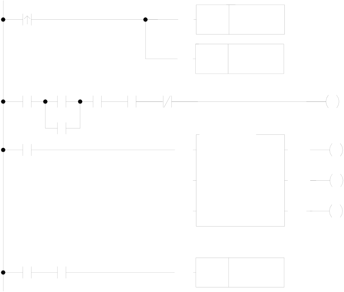
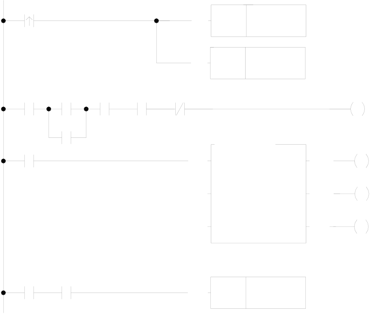
Example for FUN140 Program Application
Program example: Jog forward
As the jog forward button has been pressed for less than 0.5 second (changeable), it sends out only one (changeable) pulse;
As the jog forward button has been pressed for more than 0.5 second (changeable), it continuously sends pulses out (the frequency is 10KHz, changeable), until the release of the jog forward button to stop the pulse transmitting; or it may be designed to send N pulses out at the most.
|
Jog forward button |
Condition |
M1 |
EN |
RST |
M1 |
M0 |
• Clear finish signal. |
||
|
Jog |
EN |
RST |
R2000 |
• Perform from the first step every time. |
|||||
|
forward |
Servo |
Manual |
|||||||
|
button |
Ready |
operation |
for action |
||||||
M0
|
M0 |
EN |
140.HSPSO |
ACT |
M1000 |
|
|
Ps |
: 0 |
||||
|
Positioning Program: |
PAU |
SR |
: R 5000 |
ERR |
M1001 |
|
001 SPD 1000 |
|||||
|
WR |
: R 2000 |
||||
|
DRV ADR,+,1,Ps |
|||||
|
WAIT TIME,50 |
ABT |
DN |
M1002 |
||
|
GOTO NEXT |
|||||
|
002 SPD 10000 |
|||||
DRV ADR,+,999999,Ut
MEND
|
M0 |
M1996 |
EN |
SET |
M1 |
• When the last step been complete, |
|
set finish signal. |
Program example: Jog Backward
As the jog backward button has been pressed for less than 0.5 second (changeable) it sends out only one (changeable) pulse;
As the jog backward button has been pressed for more than 0.5 second (changeable), it continuously sends pulses out (the frequency is 10KHz, changeable), until the release of the jog backward button to stop the pulse transmitting; or it may be designed to send N pulses out at the most.
|
Jog forward button |
Condition |
M3 |
EN |
RST |
M3 |
M2 |
• Clear finish signal. |
||
|
Jog |
Servo |
Manual |
EN |
RST |
R2007 |
•Perform from the first step every time. |
|||
|
forward |
|||||||||
|
button |
Ready |
operation |
for action |
||||||
M2
|
M2 |
EN |
140.HSPSO |
ACT |
M1003 |
|
|
Ps |
: 0 |
||||
|
Positioning Program: |
PAU |
SR: : R 5020 |
ERR |
M1004 |
|
|
WR |
: R 2007 |
||||
|
001 SPD 1000 |
|||||
|
DRV ADR,−,1,Ps |
ABT |
DN |
M1005 |
||
|
WAIT TIME,50 |
|||||
|
GOTO NEXT |
|||||
002 SPD 10000
DRV ADR,−,999999,Ut
MEND
|
M2 |
M1996 |
EN |
SET |
M3 |
• When the last step been complete, |
|
set finish signal. |







NC Positioning Instruction
|
FUN 141 |
Instruction of Parameter Setting for Positioning Program |
FUN 141 |
|
|
MPARA |
MPARA |
||
|
|
Ps: The set number of Pulse Output (0~3). |
||



SR: Starting register for parameter table, it has totally 18
|
|
|
|
|
HR |
DR |
parameters which controlled by 24 registers. |
|
|
Range |
ROR |
K |
|||||
|
R0 |
D0 |
R5000 |
|||||
|
Ope- |
|||||||
|
∣ |
∣ |
∣ |
|||||
|
rand |
R3839 |
D3999 |
R8071 |
||||
|
Ps |
0~3 |
||||||
|
○ |
○ |
||||||
|
SR |
○ |
||||||





Instruction explanation
1.This instruction is not necessary if the system default for parameter value is matching what users need. However, if it needs to open the parameter value to do dynamic modification, this instruction is required.
2.This instruction incorporates with FUN140 for positioning control purpose, each axis can have one FUN140 instruction only.
3. Whether the execution control input “EN” = 0 or 1, anyway, this instruction will be performed.
4. When there is error in parameter value, the output indication “ERR” will be ON, and the error code is appeared in the error code register.
Explanation for the parameter table:
SR =Starting register of parameter table, suppose it is R2000.
|
R2000 |
0~2 |
Parameter 0 |
System default =1 |
|
R2001 |
1~65535 Ps/Rev |
Parameter 1 |
System default =2000 |
1~999999µM/Rev
|
DR2002 |
1~999999 mDeg/Rev |
Parameter 2 |
System default =2000 |
1~999999×0.1 mInch/Rev
|
R2004 |
0~3 |
Parameter 3 |
System default =2 |
|
DR2005 |
1~921600 Ps/Sec |
Parameter 4 |
System default =460000 |
|
1~153000 |
|||
|
DR2007 |
0~921600 Ps/Sec |
Parameter 5 |
System default =141 |
|
1~153000 |
|||
|
R2009 |
1~65535 Ps/Sec |
Parameter 6 |
System default =1000 |
|
R2010 |
0~32767 |
Parameter 7 |
System default =0 |
|
R2011 |
0~30000 |
Parameter 8 |
System default =5000 |
|
R2012 |
0~1 |
Parameter 9 |
System default =0100H |
|
R2013 |
-32768~32767 |
Parameter 10 |
System default =0 |
|
R2014 |
-32768~32767 |
Parameter 11 |
System default =0 |
|
R2015 |
0~30000 |
Parameter 12 |
System default =0 |
|
R2016 |
0~30000 |
Parameter 13 |
System default =500 |
|
DR2017 |
0~1999999 |
Parameter 14 |
System default =0 |
|
DR2019 |
00H~FFH |
Parameter 15 |
System default =FFFFFFFFH |
|
DR2021 |
-999999~999999 |
Parameter 16 |
System default =0 |
|
R2023 |
0~255 |
Parameter 17 |
System default =1 |
NC Positioning Instruction
|
FUN 141 MPARA |
Instruction of Parameter Setting for Positioning Program |
FUN 141 MPARA |
||||||||||||||||||||||||||||||||||||
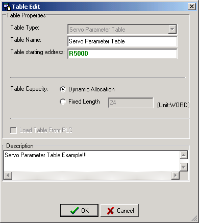
Click the “Servo Parameter Table” Item which in project windows :
Servo Parameter Table Æ Click right button and select “New Table”
● Table Type : It will be fixed to ” Servo Parameter Table ”. ● Table Name : For modify or debug, you can give a convenient name. ● Table Starting address : Enter the address which Starting register of Servo Parameter Table. |
||||||||||||||||||||||||||||||||||||||
NC Positioning Instruction
|
FUN 141 MPARA |
Instruction of Parameter Setting for Positioning Program |
FUN 141 MPARA |
||||||||||||||||
|
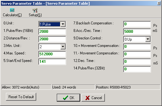
Explanation for the parameter: z Parameter 0: The setting of unit, its default is 1. y When the setting value is 0, the moving stroke and speed setting in the positioning program will all be assigned with the unit of mm, Deg, Inch, so called machine unit. y When the setting value is 1, the moving stroke and speed setting in the positioning program will all be assigned with the unit of Pulse, so called motor unit. y When the setting value is 2, the moving stroke setting in the positioning program will all be assigned with the unit of mm, Deg, Inch, and the speed setting will all be assigned with the unit of Pulse/Sec, which is called as compound unit.
z Parameter 1: Pulse count/1-revolution, its default is 2000, i.e. 2000 Ps/Rev. y The pulse counts needed to turn the motor for one revolution z Parameter 2: Movement/1 revolution, its default is 2000, i.e. 2000 Ps/Rev. y The movement while motor turning for one revolution. B=1~999999 µM/Rev |
||||||||||||||||||

NC Positioning Instruction
|
FUN 141 MPARA |
Instruction of Parameter Setting for Positioning Program |
FUN 141 MPARA |
|||||||||||||||||||||||||||||||||||||||
|
z Parameter 3: The resolution of moving stroke setting, its default is 2.
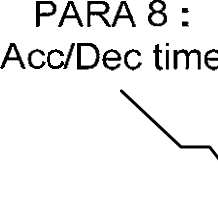
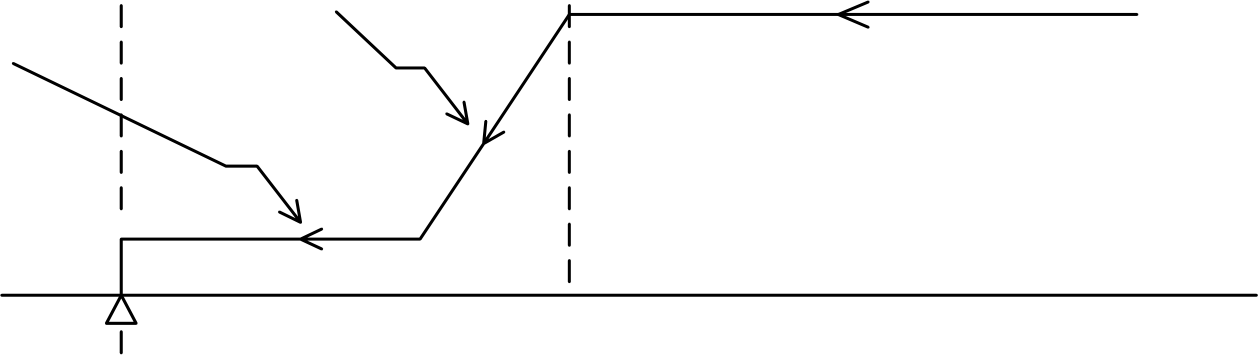
z Parameter 4: The limited speed setting, its default is 460000, i.e. 460000 Ps/Sec. y Motor and compound unit: 1~921600 Ps/Sec. y Machine unit: 1~153000 (cm/Min, ×10 Deg/Min, Inch/Min). f_max =(V_max ×1000×A)/(6×B)≤ 921600 Ps/Sec Note: A = Parameter 1, B =Parameter 2. z Parameter 5: Initiate/Stop speed, the default = 141. y Motor and compound unit: 1~921600 Ps/Sec. y Machine unit: 1~15300 (cm/Min, ×10 Deg/Min, Inch/Min). However, the limited frequency can’t be greater than 921600 Ps/Sec. z Parameter 6: Creep speed for machine zero return; the default is 1000. Motor and compound unit: 1~65535 Ps/Sec z Parameter 7: Backlash compensation, the default =0. y Setting range: 0~32767 Ps. y While backward traveling, the traveling distance will be added with this value automatically. z Parameter 8: Acceleration/Deceleration time setting, the default = 5000, and the unit is mS. y Setting range: 0~30000 mS. y The setting value represents the time required to accelerate from idle state up to limited speed state or decelerate from the limited speed state down to the idle state. y The acceleration/deceleration is constant slope depending on Parameter 4 / Parameter 8 y When Parameter 12 = 0, Parameter 8 is the deceleration time z Parameter 9: Rotation and zero return direction; the default is 0100H (Not used in linear interpolation mode) b15 b8 b7 b0
|
|||||||||||||||||||||||||||||||||||||||||
NC Positioning Instruction
|
FUN 141 MPARA |
Instruction of Parameter Setting for Positioning Program |
FUN 141 MPARA |
||||||
|
y Parameter 9-0: Rotation direction setting; the default is 0 Setting value =1, the present value decreases while in forward pulse output; the present value increases while in backward pulse output. y Parameter 9-1: Zero return direction setting; the default is 1 Setting value =1, direction in which the present value decreases. z Parameter 10: Forward movement compensation, the default = 0. y Setting range: −32768~32767 Ps. y When it is in forward pulse output, it will automatically add with this value as the moving distance. z Parameter 11: Backward movement compensation, the default =0. y Setting range: −32768~32767 Ps. y When it is in backward pulse output, it will automatically add with this value as the moving distance. z Parameter 12: Deceleration time setting, the default =0, and the unit is mS. y Setting range: 0~30000 mS. y When Parameter 12 = 0, Parameter 8 is the deceleration time y When Parameter 12 ≠ 0, Parameter 12 is the deceleration time z Parameter 13: Interpolation time constant; the default is 500. y Setting range: 0~30000 mS. y Set the time required to achieve the speed specified by the program. (The initiate speed is always regarded as “0.) z Parameter 14: Pulse count/1-revolution, the default = 0. y The pulse counts needed to turn the motor for one revolution z Parameter 15: I/O control interface for DRVZ; the default is FFFFFFFFH b15 b8 b7 b0
y Parameter 15-0: Setting of DOG input (SR+19), it must be the input of the main unit b6~b0: Reference number of DOG input (0~15, it means X0~X15) b7=0: Contact A or Normal Open |
||||||||
NC Positioning Instruction
|
FUN 141 MPARA |
Instruction of Parameter Setting for Positioning Program |
FUN 141 MPARA |
||||||||
|
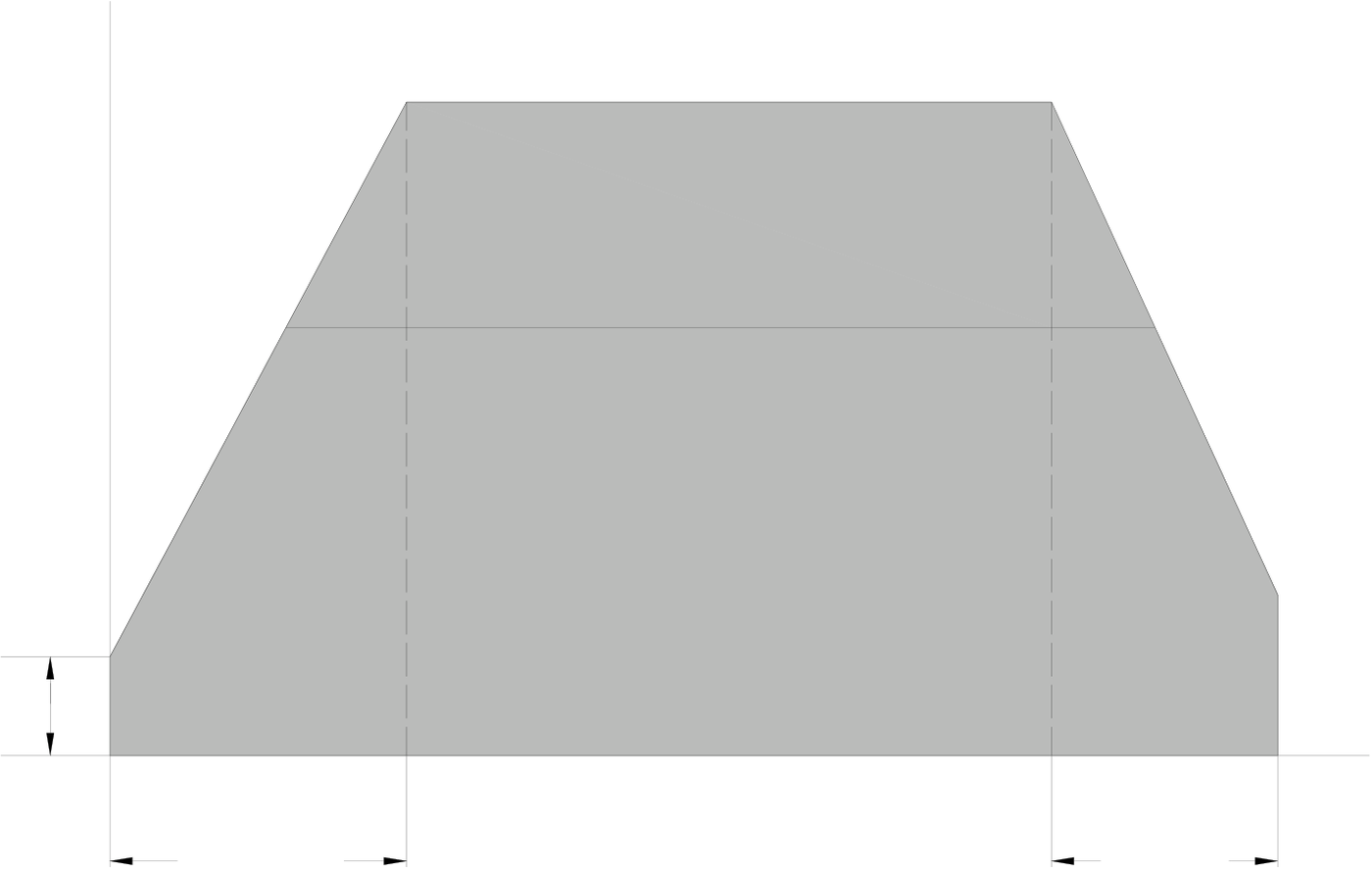
zParameter 15-1: Setting of stroke limit input (SR+19) b14~b8: Reference number of limit input (0~125, it means X0~X125) b15 = 0 : Contact A or Normal Open zParameter 15-2: Setting of PG0 signal input (SR+20), it must be the input of the main unit b6~b0: Reference number of PG0 input (0~15, it means X0~X15) b7= 0 : Start counting at front end of sensing DOG input zParameter 15-3: Setting of CLR signal output (SR+20), it must be the output of the main unit b15~b8: Reference number of CLR output (0~23, it means Y0~Y23) b15~b8 =FFH, without CLR output z Parameter 16: Machine zero point address; the default is 0. Setting range: -999999 ~ 999999 Ps z Parameter 17: Number of zero point signals (Sensing of PG0 input); the default is 1. Setting range : 0~255 count Speed Parameter 4 : Max. speed Work speed Parameter 5
. For reference with FUN140 instruction |
||||||||||
NC Positioning Instruction
|
FUN 141 |
Instruction of Parameter Setting for Positioning Program |
FUN 141 |
|
MPARA |
MPARA |
Speed
Work Speed
Parameter 5
|
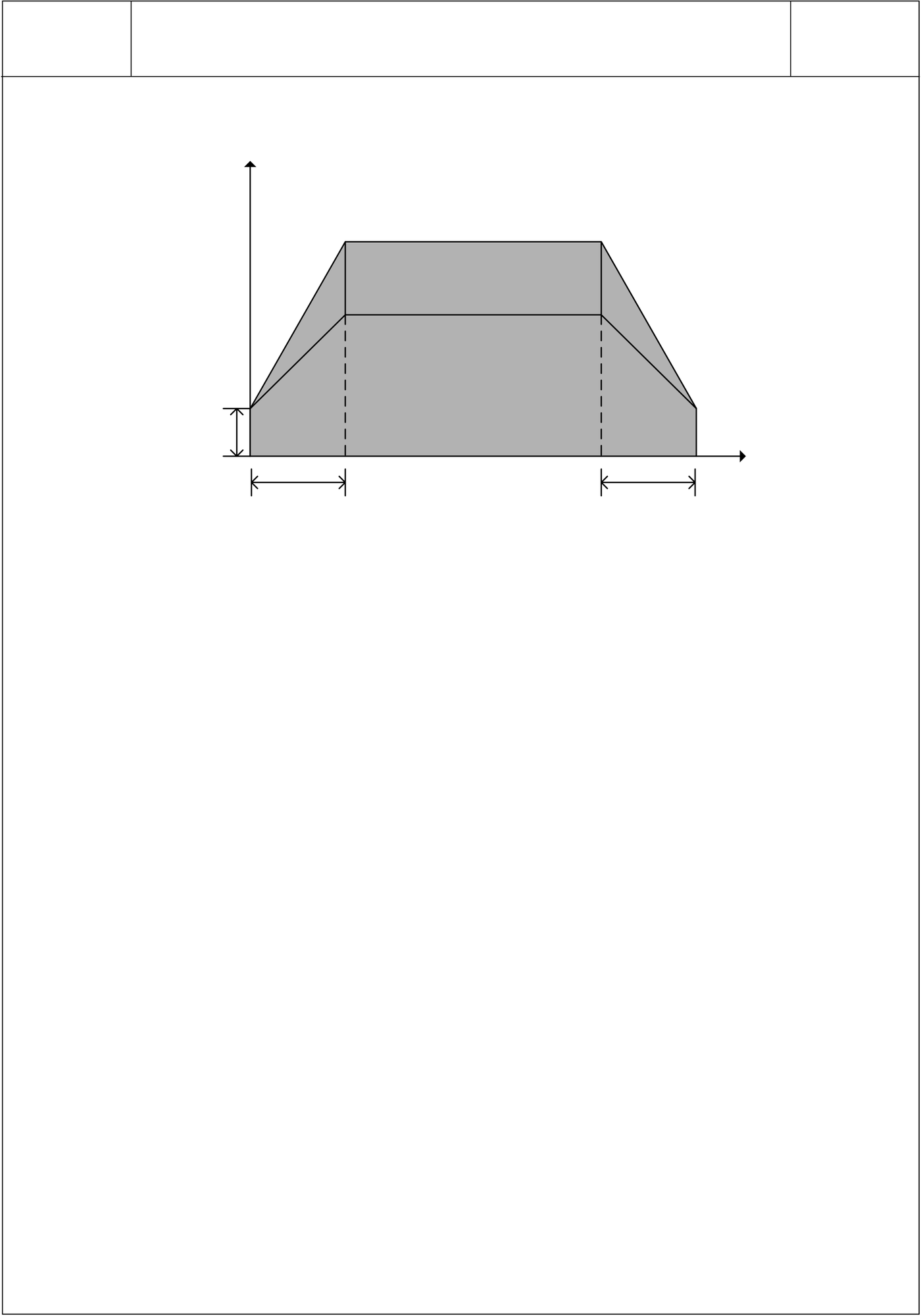
Initiate/Stop speed Parameter 13 Interpolation time constant |
Time Parameter 13 Interpolation time constant |
. For reference with FUN147 instruction
※ The parameter 13 of the axis with longest movement is used for acceleration and deceleration control for linear interpolation if each axis owns its own motion parameter table
※ Using the same motion parameter table (through FUN141 and give the same starting address of SR operand for each axis) for the simultaneous linear interpolation axes, it is the best way for multi-axis linear interpolation motion control










NC Positioning Instruction
|
FUN 142 P PSOFF |
Enforcing to Stop Pulse Output |
FUN 142 P PSOFF |
||||
to stop its output.
|
||||||
|
Instruction Explanation number of Pulse Output to stop its output. 2. When applying in the process of return home , as the home has returned, it can immediately stop the pulse output by using this instruction, so as to make it stop at the same position every time when performing machine homing. Program example ; When M0 changes from 0→1, it enforces the
|
||||||


















NC Positioning Instruction
|
FUN 143 P |
EN |
Converting the Current Pulse Value to the Displaying Value |
FUN 143 P |
|
|
PSCNV |
(mm, Deg, Inch, PS) |
PSCNV |
||
|
Execution control |
Ladder symbol |
Ps: 0~3; converting the assigned pulse position to mm (Deg, |
||
|
143P.PSCNV |
Inch, PS) which has the same unit as the set point, so |
|||
|
Ps : |
as to make the current position displayed. |
|||
|
D : |
D: Registers that store the current position after conversion. It uses 2 registers, e.g. D10 represents D10 (Low |
|||
Word) and D11 (High Word) two registers.
|
Range |
HR |
DR |
ROR |
K |
|
R0 |
D0 |
R5000 |
2 |
|
|
Ope- |
||||
|
∣ |
∣ |
∣ |
∣ |
|
|
rand |
R3839 |
D3999 |
R8071 |
256 |
|
Ps |
0~3 |
|||
|
○ |
○ |
○* |
||
|
D |
Instruction Explanation
1. When execution control “EN” =1 or changes from 0→1( P instruction), this instruction will convert the assigned current pulse position (PS) to be the mm (or Deg, Inch, or PS) that has the same unit as the set value, so as to make current position displaying.
2. After the FUN140 and FUN 147 instructions have been performed, it will then be able to get the correct conversion value by executing this instruction.
Program Example
; When M0=1, it converts the current pulse position of
Ps0 (DR4088) to the mm (or Deg or Inch or PS) that
has the same unit as the set value, and store it into the
DD10 to make the current position displaying.

NC Positioning Instruction
|
FUN147 MHSPO |
Multi-Axis High Speed Pulse Output |
FUN147 MHSPO |
||||||||||||||||||||||||||||||||||||||||
|
||||||||||||||||||||||||||||||||||||||||||
|
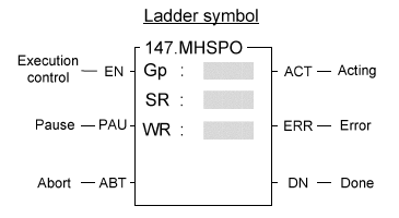
Instruction Explanation 1. The FUN147 (MHSPO) instruction is used to support the linear interpolation for multi-axis motion control, it consists of the motion program written and edited with tex programming. We named every position point as a step (which includes output frequency, traveling distance, and transfer conditions). Every step of positioning point owns 15 registers for coding. 2. The FUN147 (MHSPO) instruction can support up to 4 axes for simultaneous linear interpolation; or 2 sets of 2-axis linear interpolation (i.e. Gp0 = Axes Ps0 & Ps1 ; Gp1 = Axes Ps2 & Ps3) 3. The best benefit to store the positioning program into the registers is that in the case of association with MMI (Man Machine Interface) to operate settings, it may save and reload the positioning program via MMI when replacing the molds. 4. When execution control “EN”=1, if the other FUN147/FUN140 instructions to control Ps0~3 are not active (corresponding status of Ps0=M1992, Ps1=M1993, Ps2=M1994, and Ps3=M1995 will be ON), it will start to execute from the next step of positioning point (when goes to the last step, it will be restarted from the first step to perform); if Ps0~3 is controlled by other FUN147/FUN140 instruction (corresponding status of Ps0=M1992, Ps1=M1993, Ps2=M1994, and Ps3=M1995 would be OFF), this instruction will acquire the pulse output right of positioning control once the controlling FUN147/FUN140 has released the control right. 5. When execution control input “EN” =0, it stops the pulse output immediately. 6. When output pause “PAU” =1 and execution control “EN” was 1 beforehand, it will pause the pulse output. When output pause “PAU” =0 and execution control is still 1, it will continue the unfinished pulse output. 7. When output abort “ABT”=1, it stops pulse output immediately. (When the execution control input “EN” becomes 1 next time, it will restart from the first step of positioning point to execute.) 8. While the pulse is in output transmitting, the output indication “ACT” is ON. 9. When there is execution error, the output indication “ERR” will be ON. (The error code is stored in the error code register.) 10.When each step of positioning point is complete, the output indication “DN” will be ON. |
||||||||||||||||||||||||||||||||||||||||||
NC Positioning Instruction
|
FUN147 MHSPO |
Multi-Axis High Speed Pulse Output |
FUN147 MHSPO |
||||||||||||||||||||||||||||||||||||||||||||||
|
*** The working mode of Pulse Output must be set (without setting, Y0~Y7 will be treated as general output) to be one of U/D, or A/B mode, thus the Pulse Output may have a regular output. Y1 (Y3, Y5, Y7), it sends out downward counting pulse. A/B mode : Y0 (Y2, Y4, Y6), it sends out the phase A pulse. Y1 (Y3, Y5, Y7), it sends out the phase B pulse. ● The output polarity for Pulse Output can select to be Normal ON or Normal OFF. 【The interfaces for positioning control】
※ FUN147 doesn’t support dynamic change for its output frequency during the pulse transmitting. |
||||||||||||||||||||||||||||||||||||||||||||||||
NC Positioning Instruction
|
FUN147 |
Multi-Axis High Speed Pulse Output |
FUN147 |
|
|
● |
Format of positioning program with linear interpolation: |
||
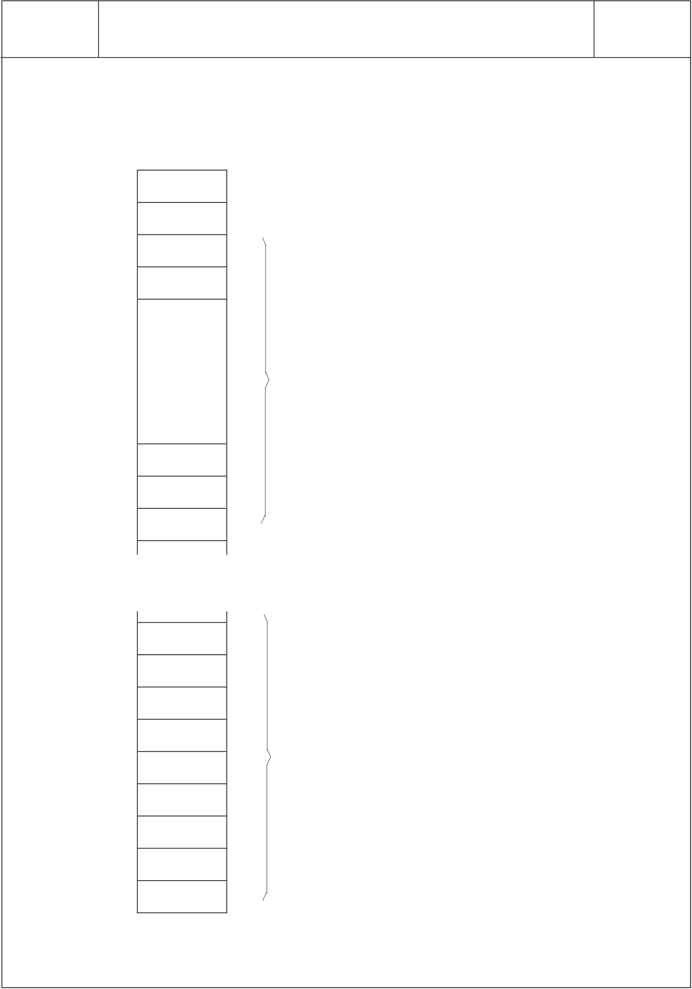
SR:Starting register of registers block which reserved to store positioning program, explained as follows:
|
SR |
A55CH |
;The effective positioning program; its starting register must be A55CH |
|
SR+1 |
Total steps |
SR+2
SR+3
|
● |
● |
The first positioning point (step) of positioning program |
|
● |
● |
|
|
● |
● |
|
|
● |
● |
(every step owns 15 registers for coding). |
SR+14
SR+15
SR+16
The Nth step of positioning program.
SR+N×15+2
NC Positioning Instruction
|
FUN147 MHSPO |
Multi-Axis High Speed Pulse Output |
FUN147 MHSPO |
|||||||||||
|
●Explanation for working register of instruction operation : WR is the starting of working registers.
WR+0 : If this instruction is in execution, the content of this register represents the step (1~N) being performed. If this instruction is not in execution, the content of this register represents the step where it stopped at present Before starting the execution control “EN” =1, the user can renew the content of WR+0 to determine starting from which step to perform (when the content of WR+0 =0, and execution control “EN” =1, it represents that the execution starts from the first step). WR+1 : B0~B7, total steps *** When step which has been completed, the output indication “DN” will turn ON and keep such status if suspending ; the user may turn OFF the status of “DN” by using the rising edge of output coil controlled by "DN" to clear the content of WR+1 register to be 0, and it can be attained. |
|||||||||||||

NC Positioning Instruction
|
FUN147 |
0 |
Multi-Axis High Speed Pulse Output |
FUN147 |
|
MHSPO |
MHSPO |
||
|
Error code |
|||
|
Error indication |
|||
|
R4060(Ps0) |
:Error free |
||
|
R4061(Ps1) |
1 |
:Parameter 0 error |
The possible error codes |
|
R4062(Ps2) |
2 |
:Parameter 1 error |
|
|
R4063(Ps3) |
3 |
:Parameter 2 error |
|
|
D4060(Gp0) |
4 |
:Parameter 3 error |
|
|
D4061(Gp1) |
5 |
:Parameter 4 error |
|
|
6 |
:Parameter 5 error |
||
|
7 |
:Parameter 6 error |
For FUN141 execution |
|
|
8 |
:Parameter 7 error |
The possible error codes |
|
|
9 |
:Parameter 8 error |
||
|
10 |
:Parameter 9 error |
||
|
13 |
:Parameter 12 error |
||
|
14 |
:Parameter 13 error |
||
|
15 |
:Parameter 14 error |
||
|
30 |
:Error of variable address for speed setting |
||
|
31 |
:Error of setting value for speed setting |
||
|
32 |
:Error of variable address for stroke setting |
||
|
33 |
:Error of setting value for stroke setting |
||
|
34 |
:Illegal positioning program |
||
|
35 |
:Length error of total step |
||
|
36 |
:Over the maximum step |
||
|
37 |
:Limited frequency error |
||
|
38 |
:Initiate/stop frequency error |
||
|
39 |
:Over range of compensation value for movement |
For FUN140 and |
|
|
40 |
:Over range of moving stroke |
FUN147 execution |
|
|
41 |
:ABS positioning is not allowed within DRVC commands |
||
|
42 |
:DRVZ can’t follow DRVC |
||
|
50 |
:Illegal operation mod of DRVZ |
||
|
51 |
:Illegal DOG input number |
||
|
52 |
:Illegal PG0 input number |
||
|
53 |
:Illegal CLR output number |
||
|
60 |
:Illegal linear interpolation command |
Note : The content of error indication register will keep the latest error code. Making sure that no more error to happen, you can clear the content of error indication register to be 0, and it still maintains the value at 0.
NC Positioning Instruction
|
FUN147 MHSPO |
Multi-Axis High Speed Pulse Output |
FUN147 MHSPO |
|||||||||
|
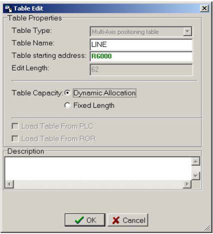
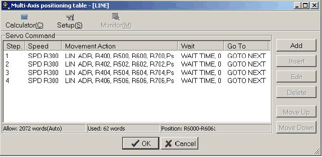
Editing Servo Program Table with WinProladder Click the “Servo Program Table” item which in project window: Project Name
● Table Type: Multi-Axis positioning table ● Table Name: For modify or debug, you can give a convenient name. ● Table Starting address: Enter the address which Starting register
|
|||||||||||
NC Positioning Instruction
|
FUN147 MHSPO |
Multi-Axis High Speed Pulse Output |
FUN147 MHSPO |
|||||||||
|
z For easy programming and trouble shooting, the WinProladder provides the text editing environment to edit the motion program (servo program table) for FUN147 execution. z Extended positioning instructions for linear interpolation are listed as follows:
|
|||||||||||
NC Positioning Instruction
|
FUN147 MHSPO Instruction LINE |
Multi-Axis High Speed Pulse Output |
FUN147 |
||
|
Operand |
Explanation |
|||
|
ADR,X,Y,Z,W,Ut |
yLINE is used for linear interpolation in endless movement |
|||
|
or or ABS Ps |
yThere are 6 operands to construct LINE instruction as LIN’s Description |
|||
Where,
X:Stroke setting of Ps0 Y:Stroke setting of Ps1 Z:Stroke setting of Ps2 W:Stroke setting of Ps3
yThe stroke setting for each axis means the output ratio between the active axes, the axis with longest movement is followed by others
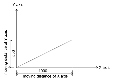
i.e. In LINE mode, if the stroke settings are 1000、500、300、0( In
Ps), it means if Ps0 axis sends 1000Ps, then Ps1 and Ps2 will send 500Ps and 300Ps respectively. (Axis Ps3 doesn’t work due to the setting value is 0).
It will follow this ratio (1000/500/300/0) for pulse output until the FUN147 instruction is stopped or exists from the LINE mode.
Note: Comparison explanation between the relative coordinate positioning (ADR) and the absolute coordinate
positioning (ABS)
To move from position 30000 to -10000, the coding for programming is:
DRV ADR,−,40000,Ut or DRV ABS, ,−10000,Ut
|
... |
-10000 |
0 |
10000 |
20000 |
30000 |
... |
|
Ut |
To move from position−10000 to 10000, the coding for programming is: DRV ADR,+,20000,Ut or DRV ABS,,10000,Ut
|
Instruction |
Operand |
Explanation |
|
WAIT |
TIME,XXXXX |
y When pulse output is complete, performing the wait instruction to |
|
go to the assigned step. There are 5 kind of operands that |
||
|
or Rxxxx |
explained as follows: |
|
|
or Dxxxx |
Time: The waiting time (the unit is 0.01 second), it can be directly |
|
|
input with constant or variable (Rxxxx or Dxxxx); when it is |
time up, performs the step that assigned by GOTO.
|
or X0~X255 |
X0~X255: Waiting until the input status is ON, it performs the step that assigned by GOTO. Y0~Y255:Waiting until the output status is ON, it performs the step that assigned by GOTO. |
M0~M1911: Waiting until the internal relay is ON, it performs the step that assigned by GOTO.
S0~S999: Waiting until the step relay is ON, it performs the step that assigned by GOTO.
NC Positioning Instruction
|
FUN147 MHSPO |
Multi-Axis High Speed Pulse Output |
FUN147 MHSPO |
|||||||||||
First, it must complete the FUN147 instruction before the editing of positioning program, and assigned in FUN147 instruction the starting register of registers block to store positioning program. While editing the positioning program, it will store the newly edited positioning program to the assigned registers block; for every one positioning point (called as one step) edited, it owns 15 registers for coding. If there are N positioning points, it will be used by N × 15 + 2 registers in total. Note: The registers storing the positioning program can not be repeated in using! z Format and example for the positioning program with linear interpolation: 001 SPD 5000 ;Vector speed is 5KHz LIN ADR,500,400,300,200,Ut ;Moving forward 500(Ps0)/400(Ps1)/300(Ps2)/200(Ps3) units WAIT TIME,100 ;Wait for 1second GOTO NEXT ;Perform the next step 002 SPD R1000 ;Vector speed is stored in DR1000(R1001 and R1000) LIN ADR,D100,D200, , ,Ut ;Moving stroke is stored in DD100(Ps0) & DD200(Ps1) WAIT TIME,R500 ;The waiting time is stored in R500 GOTO NEXT ;To perform the next step 003 SPD R1002 ;Vector speed is stored in DR1002(R1003 and R1002) LIN ADR,0,0,R300,R400,Ps ;Moving stroke is stored in DR300(Ps2) & DR400(Ps3) WAIT X0 ;Wait until X0 ON GOTO 1 ;Perform the first step |
|||||||||||||
NC Positioning Instruction
|
FUN147 MHSPO |
Multi-Axis High Speed Pulse Output |
FUN147 MHSPO |
||
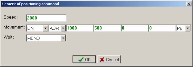
The positioning program with linear interpolation instruction as below:
It means the moving stroke setting for axis Ps0(X axis) is 1000 Ps, for axis Ps1(Y axis) is 500 Ps; both axes Ps2 and Ps3 are inactive due to the setting values are 0.
|
||||


NC Positioning Instruction
|
FUN148 MPG |
Manual Pulse Generator For Positioning |
FUN148 MPG |
|||||||||||||||||||||||||||||||||||||||||||||||||||||||||||||||||||||||||||||||||||||||||||
speed timer to generate 50mS fixed time interrupt service to have accurate repeat time to sample the pulse input from manual pulse generator. If it comes the input pulses, it will calculate the number of pulses needing to output according to the setting of multiplier (Mr+0 and Mr+1), and then outputs the pulse stream in the speed of setting (Fo) during this time interval. The setting of output speed (Fo) must be fast enough, and the acceleration / deceleration rate ( Parameter 4 and parameter 8 of FUN141 instruction) must be sharp to guarantee it can complete the sending of pulse stream during the time interval if it is under high multiplier (100 or 200 times) situation. ● When execution 〝EN〞=1, this instruction will sample the pulse input from manual pulse generator by reading the current value of assigned high speed counter every time interval; it doesn’t have any output if it doesn’t have any input pulse; but If it senses the input pulses, it will calculate the number of pulses needing to output according to the setting of multiplier (Mr+0 and Mr+1), and then outputs the pulse stream in the speed of setting (Fo) during this time interval. Number of output pulses = (Number of input pulses × Fa ) / Fb ● This instruction also under the control of hardware resource management; it wouldn’t be executed if the hardware is occupied.
|
|||||||||||||||||||||||||||||||||||||||||||||||||||||||||||||||||||||||||||||||||||||||||||||
 .Output pulse stream in
 .Output pulse stream in
NC Positioning Instruction
|
FUN148 MPG |
Manual Pulse Generator For Positioning |
FUN148 MPG |
||
|
||||
NC Positioning Instruction
|
FUN148 MPG |
Manual Pulse Generator For Positioning |
FUN148 MPG |
|
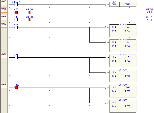
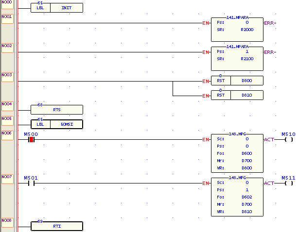
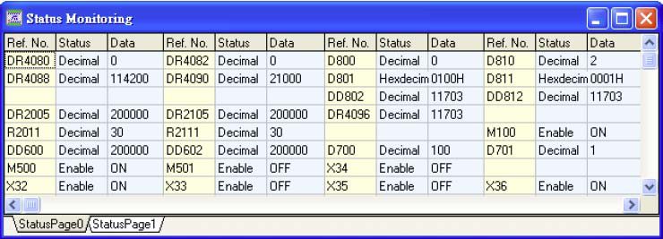
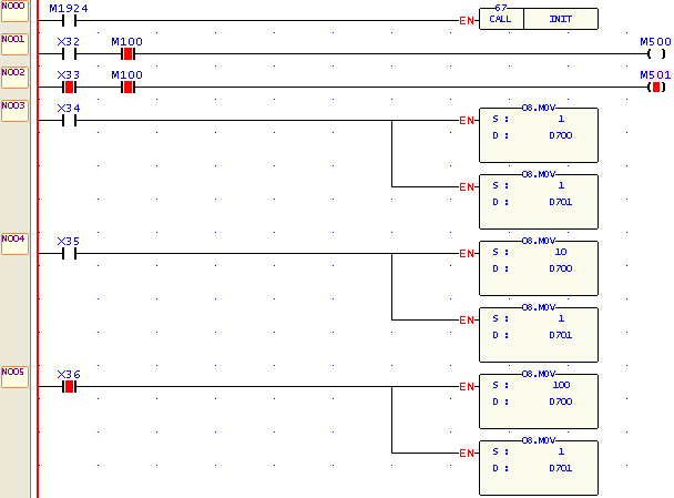
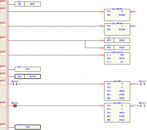
X32 :Select axis 0(Ps0) .Number of output pulses = (Number of input pulses from HSC0 × D700) / D701 |
||
NC Positioning Instruction
|
FUN148 MPG |
Manual Pulse Generator For Positioning |
FUN148 MPG |
||
|
||||
NC Positioning Instruction
|
FUN148 MPG |
Manual Pulse Generator For Positioning |
FUN148 MPG |
|
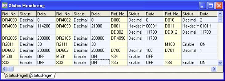
X32 : Select axis 0 (Ps0) .Number of output pulses = (Number of input pulses from HSC0 × D700) / D701 |
||
NC Positioning Instruction
|
FUN148 MPG |
Manual Pulse Generator For Positioning |
FUN148 MPG |
|
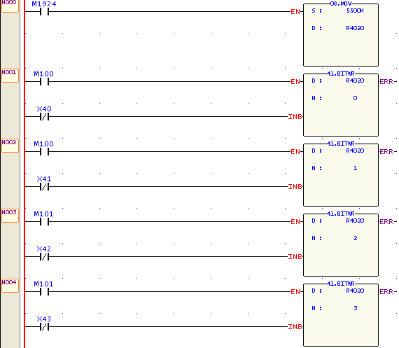
Manual Pulse Generator(FUN148,MPG) instruction supports most left/right limitation for positioning control . High byte value of R4020 ≠55H, not support this function; . Program example
|
||
11.7 Machine Homing
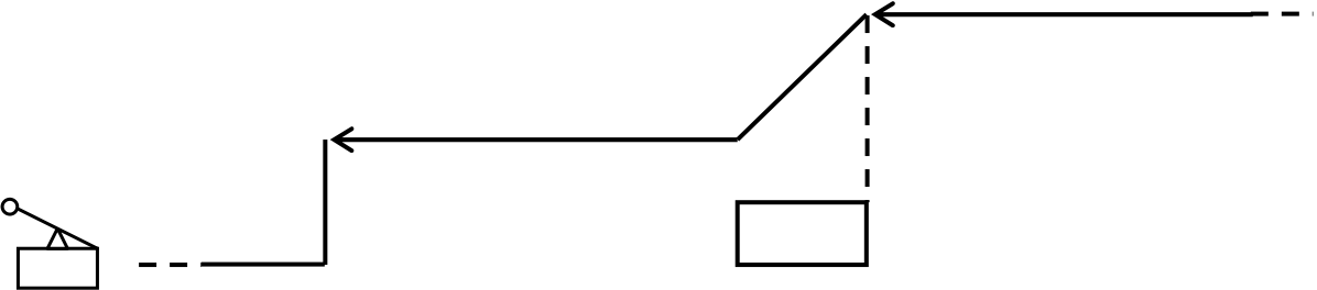
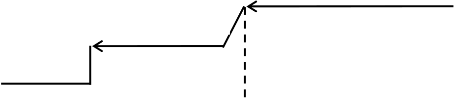
The machine set which undertakes relative model Encoder as shifting detector usually need the reset action for the reference of positioning coordinate; we called this action as machine homing (seeking for zero reference).
The machine homing diagram for NC servo unit is as follows:
Method 1:
Return home speed
Slow down speed
Left over travel limit switch Near home sensing Right over travel limit switch

When it encounters the near home signal, starts the Z phase counting.
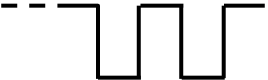
Z phase counting is up, the pulse output stops, then send out the CLR signal to clear the error counter of servo driver.
e.g.:
X3: Near home sensing input is configured as interrupt input; in the case of machine homing, it starts HSC4 to begin counting in X3+ interrupt service subroutine.
X2: Z phase counting input, it is configured as UP input of HSC4; the X2+ is prohibited to interrupt in regular time, when executing machine homing and X3 near home interrupt occurred, it starts HSC4 to begin Z phase counting. When HSC4 counting is up, it stops the pulse output, prohibit the X2+ interrupt,set home position to signal, and sends out the CLR signal to clear the error counter of servo driver. Please consult program example.
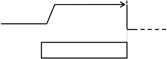
Method 2: According to application demand, it may slow down when encountering the near home sensor, while over the sensor a little far away, stop the pulse output, and then traveling slowly with backward direction; the very moment when it get out of near home sensor (the sensing signal changes from 1→0),it is treated as machine home. This program is simpler!
(1)
|
(3) |
(2) Slow down |
Home speed |
|
|
speed |
|||
|
Stop |
(4) |
Slowly |
(5) |
|
backward |
|||
|
Stop |
|||
Near home signal 1→0, machine zero reference
|
Left over travel limit switch |
Near home sensing |
Right over travel limit switch |
|
|
|


X3: Near home sensing input; it is configured as falling edge interrupt input.
•Once encountering the near home sensor, it will enable X3 falling edge interrupt, and slow down to stop within the near home sensing range.
•Slowly backward traveling until the near home sensing signal changes from 1→0.
•When the near home sensing signal changes from 1→0, it performs the X3- interrupt service subroutine immediately.
•The X3- interrupt service subroutine: Stops the pulse output immediately, prohibits the X3- interrupt, sets home position to signal, and sends out CLR signal to clear the error counter of servo driver. (Please consult the example program.)
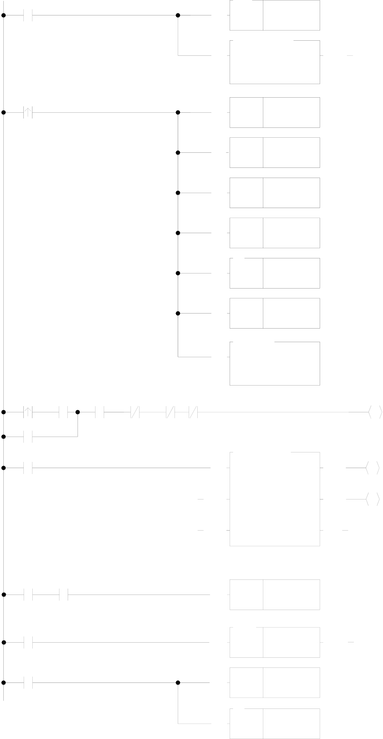
|
Program Example 1: Machine homing (method 1) |
X2: Configured as the UP input of HSC4, and connected to Z phase input.
X3: Configured as the rising edge interrupt input, and connected to near home sensing input.
【Main Program】
|
M1924 |
EN |
146 |
ERR |
• Prohibits X2+ interruption |
|
|
DIS |
X2+I |
||||
|
141.MPARA |
|||||
|
(HSC4 does not count) |
|||||
|
EN |
|||||
|
• Parameter table R2900→R2923. |
|||||
|
Ps |
: 0 |
||||
SR: R 2900
M92
|
EN |
RST |
M50 |
• Clears the homing completion signal. |
|
EN |
RST |
M5 |
|
|
• Clears the instruction completion |
|||
|
signal for homing |
|||
|
EN |
RST |
M1007 |
• Clears the error signal. |
• Clears the step pointer, it starts from
|
EN |
RST |
R 2014 |
the first step to execute. |
|
EN |
D |
R 4112 |
• Clears the current value of HSC4. |
|
RST |
• Clears the High Word of preset value
|
M92 |
SERVO |
Manual |
M5 |
M50M1007 |
EN |
RST |
R 4115 |
M4 |
for HSC4. |
|
|
08.MOV |
• Fill the preset value of HSC4 with |
|||||||||
|
EN |
||||||||||
|
S |
: R 2923 |
the content of Parameter 17 of |
||||||||
|
D |
: R 4114 |
FUN141. |
||||||||
|
READY |
operation |
|||||||||
M4
|
M4 |
Positioning program: |
EN |
140.HSPSO |
ACT |
M1006 |
• Configure R5000~R5199 as the |
|
|
Ps |
: 0 |
||||||
|
PAU |
SR |
: R 5040 |
ERR |
M1007 |
read only register (ROR) before |
||
|
001 SPD R2919 |
|||||||
|
programming, after then, when |
|||||||
|
DRV ADR,−,999999,Ut |
WR |
: R 2014 |
|||||
|
storing program, the Ladder |
|||||||
|
EXT X3 |
|||||||
|
GOTO NEXT |
ABT |
DN |
program will automatically contains |
||||
|
002 SPD R2921 |
the positioning program. |
||||||
|
DRV ADR,−,9999,Ut |
|||||||
MEND
|
M4 |
M1996 |
EN |
SET |
M5 |
TUP |
• Homing instruction completed |
|
Y8 |
EN |
.01S |
50 |
• Signal for homing completion |
||
|
T0 |
• Fill the current PS registers with 0,
|
T0 |
EN |
RST |
Y8 |
while homing completed. |
|
EN |
D |
R 4088 |
• Signal to clear error counter of servo |
|
|
driver — Y8 is ON for 0.5 second. |
||||
|
RST |
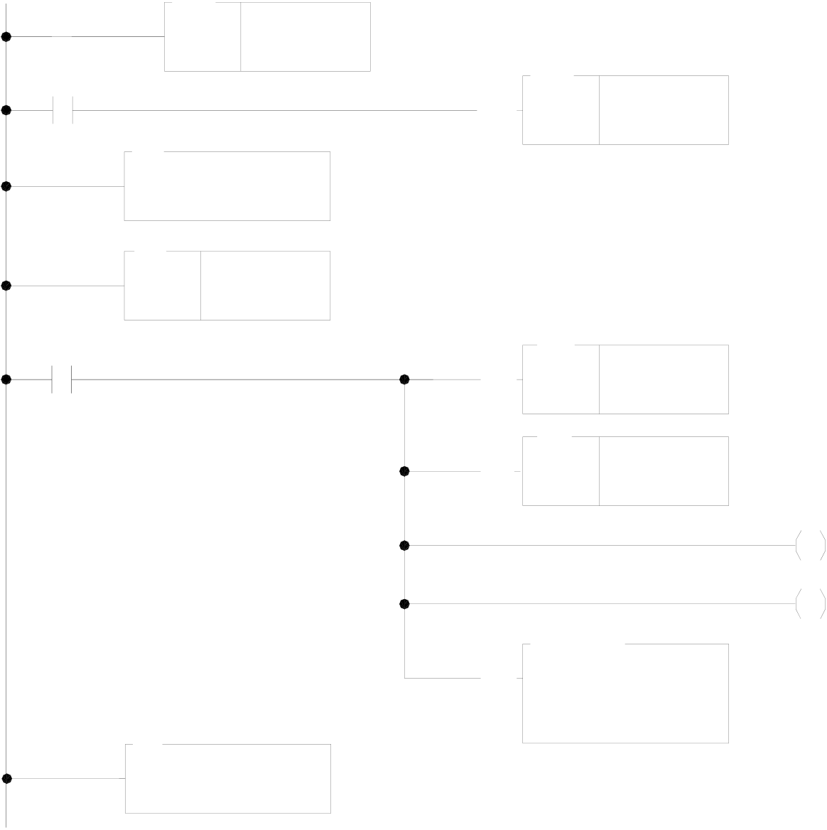
【Sub Program】
|
M4 |
65 |
X3+I |
EN |
145 |
X2+I |
• X3 rising edge interrupt service subroutine. |
|
LBL |
||||||
|
EN |
• Enables HSC4 counting if homing. |
69
RTI
|
M4 |
65 |
HSC4I |
EN |
142 |
0 |
Y8 |
• Interrupt service subroutine of HSC4 |
|
LBL |
|||||||
|
(Z phase counting is up) |
|||||||
|
• Stops pulse output immediately. |
|||||||
|
PSOFF |
|||||||
|
146 |
X2+I |
• Prohibits rising edge interrupt of X2. |
|||||
|
EN |
|||||||
|
DIS |
|||||||
|
• Output to clear error counter of servo |
|||||||
|
M50 |
driver. |
• Sets the homing completion signal.
74.IMDIO
|
EN |
D |
: Y8 |
• Sends output immediately. |
|
N |
: 1 |
69
RTI
|
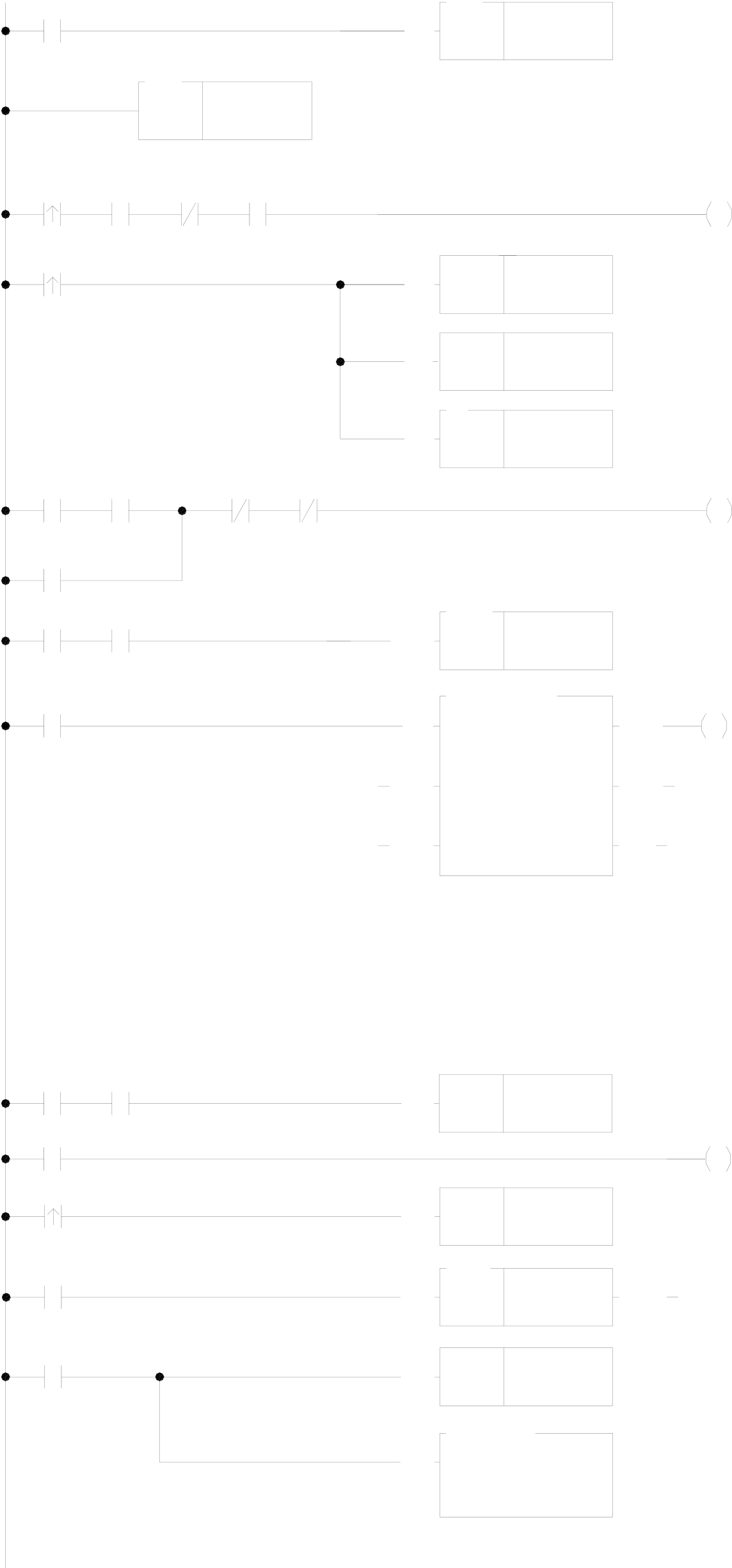
Program Example 2: Machine homing (method 2) |
X3: Connected to near home sensing input, and configured as falling edge interrupt input.
【Main Program】
|
M1924 |
EN |
67 |
INIT |
|
CALL |
65
|
Homing |
LBL |
HOME |
EN |
RST |
M50 |
M20 |
• Clears the homing completion signal. |
|||
|
Servo |
Manual |
Leftover |
||||||||
|
Ready |
operation |
travel limit |
||||||||
|
M20 |
||||||||||
|
• Clears the instruction completion |
||||||||||
|
signal for homing. |
||||||||||
|
M20 |
Servo |
EN |
RST |
M5 |
M4 |
• Clears the step pointer, it starts from |
||||
|
the first step to execute. |
||||||||||
|
D |
||||||||||
|
EN |
R2014 |
|||||||||
|
RST |
||||||||||
|
Ready |
M5 |
M50 |
||||||||
M4
|
M4 |
X3 |
145P |
ACT |
M1006 |
• Enable X3− (falling edge) interrupt. |
|||
|
EN↑EN |
X3 – I |
|||||||
|
M4 |
140.HSPSO |
• Configure R5000~R5199 to be the |
||||||
|
Positioning Program: |
EN |
Ps |
: 0 |
|||||
|
read only register (ROR) before |
||||||||
|
SR |
: R 5040 |
|||||||
|
programming, after then, when storing |
||||||||
|
001 SPD R2919 |
PAU |
WR |
: R 2014 |
ERR |
||||
|
program, the Ladder program will |
||||||||
|
DRV ADR,−,999999,Ut |
||||||||
|
EXT X3 |
ABT |
DN |
automatically contains the positioning |
|||||
|
GOTO NEXT |
program. |
|||||||
|
002 SPD 1000 |
||||||||
DRV ADR,−,1000,Ps
WAIT TIME,10
GOTO NEXT
003 SPD R200
DRV ADR,+,999999,Ut
MEND
|
M4 |
M1996 |
EN |
SET |
M5 |
TUP |
M51 |
• Homing instruction completed. |
|
M50 |
|||||||
|
M51 |
EN |
SET |
Y8 |
• Signal for homing completion. |
|||
|
Y8 |
EN |
.01S |
30 |
• Output to clear error counter of servo |
|||
|
T0 |
|||||||
|
driver — Y8 is ON for 0.3 second. |
T0
|
EN |
RST |
Y8 |
08D.MOV
|
EN |
S |
: 0 |
• Fill the current PS registers with 0. |
|
D |
: R 4088 |

【Sub Program】
65
LBL INIT
146
|
EN |
DIS |
X3 – I |
• Prohibits X3− interrupt |
141.MPARA
|
68 |
EN |
Ps |
: 0 |
ERR |
• Parameter table R2900~R2923 |
|
SR |
: 2900 |
RTS
65
|
M4 |
LBL |
X3 – I |
142 |
0 |
y X3 falling edge interrupt service |
|
|
subroutine. |
||||||
|
EN |
PSOFF |
• Stops pulse output immediately |
||||
|
X3 – I |
• Prohibits X3− interrupt |
|||||
|
146 |
||||||
|
ENDIS |
• Sets the homing completion signal. |
|||||
69
RTI
The above two machine homing examples are implemented by using Ladder program; although it is not difficult to understand, but it’s a bit cumbersome to use, which might be inconvenient for users. Since FATEK is taking into account the customer’s utility and convenience, we add machine zero return command (DRVZ) in high-speed pulse output instruction (FUN140), which provides 3 modes (MD0~MD2) of operation for different application requirement, of FBs series PLC system version (OS) V4.32 (including) or later versions.
When using DRVZ command for machine homing, it should conjoining the FUN141 motion parameter’s setting of machine zero related, it can be listed as below:
|
Parameter 6 (Creep speed) |
DRVZ MD0 |
DRVZ MD1 |
DRVZ MD2 |
|
Must be |
Must be |
Must be |
|
|
Parameter 9-1 (Return direction) |
Must be |
Must be |
Must be |
|
Parameter 15-0 (DOG input) |
Must be |
Must be |
Must be |
|
Parameter 15-1 (Limit input) |
Optional |
Optional |
Optional |
|
Parameter 15-2 (PG0 input) |
No need |
No need |
Must be |
|
Parameter 15-3 (CLR output) |
Optional |
Optional |
Optional |
|
Parameter 16 (Zero point address) |
Must be |
Must be |
Must be |
|
Parameter 17 (No. of PG0 signal) |
No need |
No need |
Must be |
The FUN 140 instruction can’t be executed for machine zero return while encountering the following situations with the error indications:
|
R4060(PS0) |
Error Code |
Explanation |
|
42 |
DRVZ can’t follow DRVC |
|
|
50 |
Illegal operation mode of DRVZ |
|
|
R4061(PS1) |
||
|
51 |
Illegal DOG input |
|
|
R4062(PS2) |
||
|
52 |
Illegal PG0 input |
|
|
R4063(PS3) |
||
|
53 |
Illegal CLR output |
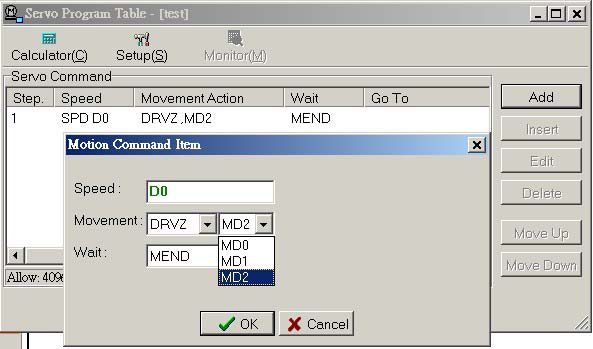
The method of using DRVZ is same as the method of two modes (DRV and DRVC) of FUN140. To see the details please choose MD0~MD2 of Movement Action mode of the servo program table in the project window (See below).












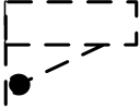
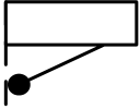
Zero return (DRVZ) operation in detailed diagram description
Mode 0




|
|

|
|

|
|
|
|



|
|
|
|


【Description】
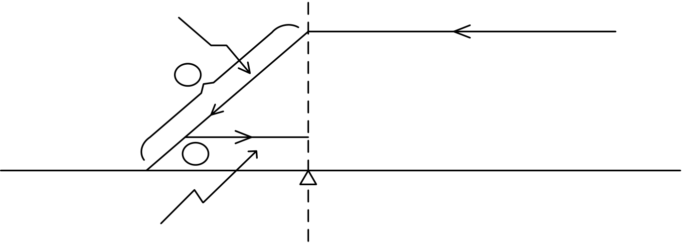
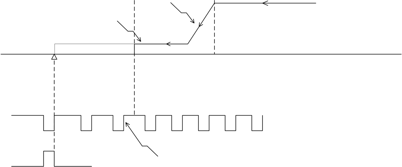
1• Zero return starts behind the DOG sensor (Parameter 15_0)
a. Moving forward to zero direction in Zero Return Speed
b. Changing the moving speed by Creep Speed (Parameter 6) while sensing the dog sensor (Edge detection and interrupt processing
c. Keeping forward until leaving the dog sensor (Edge detection and interrupt processing), it is the zero home position
d. If it doesn’t configure the CLR output (Parameter 15_3) for servo driver, the zero return process has been finished at step c.
e. If it has been configured the CLR output (Parameter 15_3) for servo driver, the zero return process will be finished after the CLR output with more than 20mS duration
2• Zero return starts at or in front of the DOG sensor (Parameter 15_0) + Stroke limit sensor (Parameter 15_1)
a. Moving forward to zero direction in zero return speed, there will stop moving while sensing the limit sensor
b. Moving backward in zero return speed and after leaving the dog sensor, it will drive the zero return procedures same as mentioned above 1.























Mode 1


|
|


|
|
|
|
|






|
|
|


【Description】
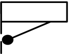
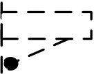
1• Zero return starts behind the DOG sensor (Parameter 15_0)
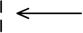
a. Moving forward to zero direction in Zero Return Speed
b. Auto slow down to stop movement while sensing the dog sensor (Edge detection and interrupt processing)
c. Delay 0.5 second, then moving backward until leaving the dog sensor (Edge detection and interrupt processing), it is the zero home position
d. If it doesn’t configure the CLR output (Parameter 15_3) for servo driver, the zero return process has been finished at step c
e. If it has been configured the CLR output (Parameter 15_3) for servo driver, the zero return process will be finished after the CLR output with more than 20mS duration
2• Zero return starts at or in front of the DOG sensor (Parameter 15_0) + Stroke limit sensor (Parameter 15_1)
a. Moving forward to zero direction in zero return speed, there will stop moving while sensing the limit sensor
b. Moving backward in zero return speed and after leaving the dog sensor, it will drive the zero return procedures same as mentioned above 1.




















Mode 2 (Front edge counting)


|
|
|
|
|
|
|
|
||||||
|
|
||||||||||||
|
|
|
|
|
|
|
|
||||||
|
|
||||||||||||
|
|
|
|||||||||||


























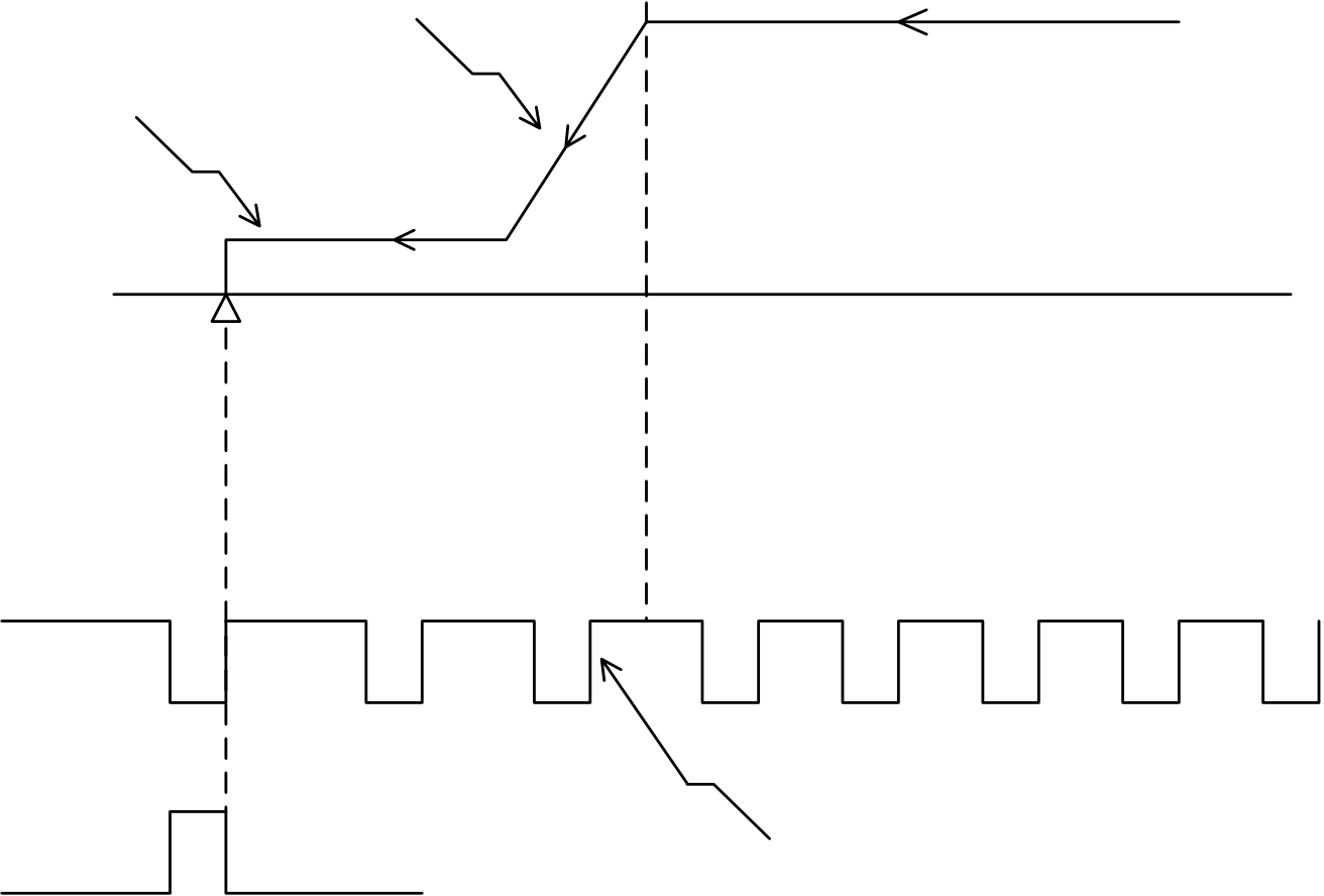
【Description】
1• Zero return starts behind the DOG sensor (Parameter 15_0)
a. Moving forward to zero direction in Zero Return Speed
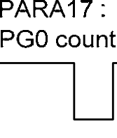
b. Changing the moving speed by Creep Speed (Parameter 6) while sensing the dog sensor (Edge detection and interrupt processing), and start counting (Edge detection and interrupt processing) the PG0 signal (Parameter 15_2)
c. While the counting value of PG0 signal is equal to the present value (Parameter 17), it is the zero home position
d. If it doesn’t configure the CLR output (Parameter 15_3) for servo driver, the zero return process has been finished at step c
e. If it has been configured the CLR output (Parameter 15_3) for servo driver, the zero return process will be finished after the CLR output with more than 20mS duration
2• Zero return starts at or in front of the DOG sensor (Parameter 15_0) + Stroke limit sensor (Parameter 15_1)
a. Moving forward to zero direction in zero return speed, there will stop moving while sensing the limit sensor
b. Moving backward in zero return speed and after leaving the dog sensor, it will drive the zero return procedures same as mentioned above 1.
※ Working at this mode, it should be noticed to adjust the correct position of dog sensor to incorporate with PG0 signal to avoid one count PG0 error for zero return processing



















|
|
|
|
|
|
|
|
|
|
|
|
|
|
|
|
|
|||||||||
|
|
|||||||||||



























【Description】
1• Zero return starts behind the DOG sensor (Parameter 15_0)
a. Moving forward to zero direction in Zero Return Speed
b. Changing the moving speed by Creep Speed (Parameter 6) while sensing the dog sensor (Edge detection and interrupt processing); keeping forward and start counting (Edge detection and interrupt processing) the PG0 signal (Parameter 15_2) while leaving the dog sensor
c. While the counting value of PG0 signal is equal to the present value (Parameter 17), it is the zero home position
d. If it doesn’t configure the CLR output (Parameter 15_3) for servo driver, the zero return process has been finished at step c
e. If it has been configured the CLR output (Parameter 15_3) for servo driver, the zero return process will be finished after the CLR output with more than 20 mS duration
2• Zero return starts at or in front of the DOG sensor (Parameter 15_0) + Stroke limit sensor (Parameter 15_1)
a. Moving forward to zero direction in zero return speed, there will stop moving while sensing the limit sensor
b. Moving backward in zero return speed and after leaving the dog sensor, it will drive the zero return procedures same as mentioned above 1.
※Working at this mode, it should be noticed to adjust the correct position of dog sensor to incorporate with PG0 signal to avoid one count PG0 error of zero return processing


The above three homing completion modes assume that starting point is nearly the right side of DOG sensor. But when implementing homing action, the starting point is possible located after DOG sensor or exactly located on DOG sensor. The following diagram and description are interpreted the homing action of two locations:
|
Zero return starts at or in front of the DOG sensor |
|||
|
|||
|
Steps g operation has started, it moves toward the homing direction (Parameter 9_1) in zero return speed until strokes the switch of limit input point (Parameter 15_1). kes the limit input point (Parameter 15_1), it immediately moving backward to the homing direction until leave the DOG sensor (sensor signal from 1 → 0). tion of the Step 2, you can determine that the starting point has returned back to the right of DOG sensor, and then it will complete the homing operation as we set the homing mode (MD0~MD2) earlier. |
|||







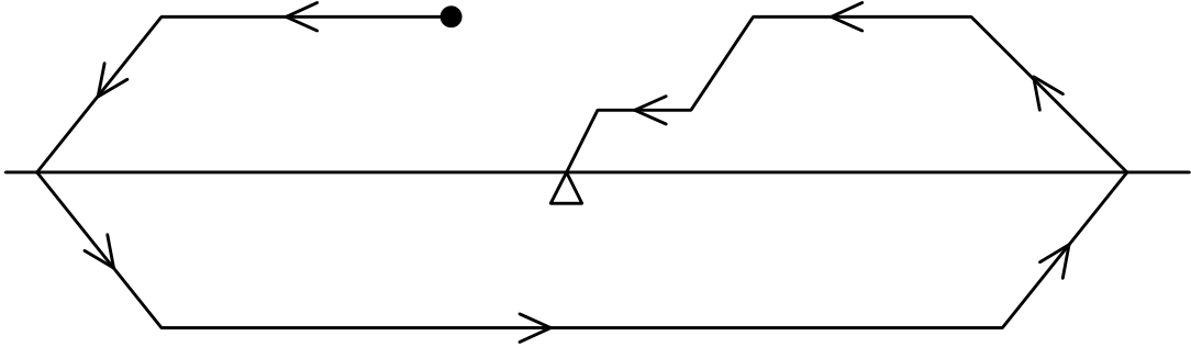




























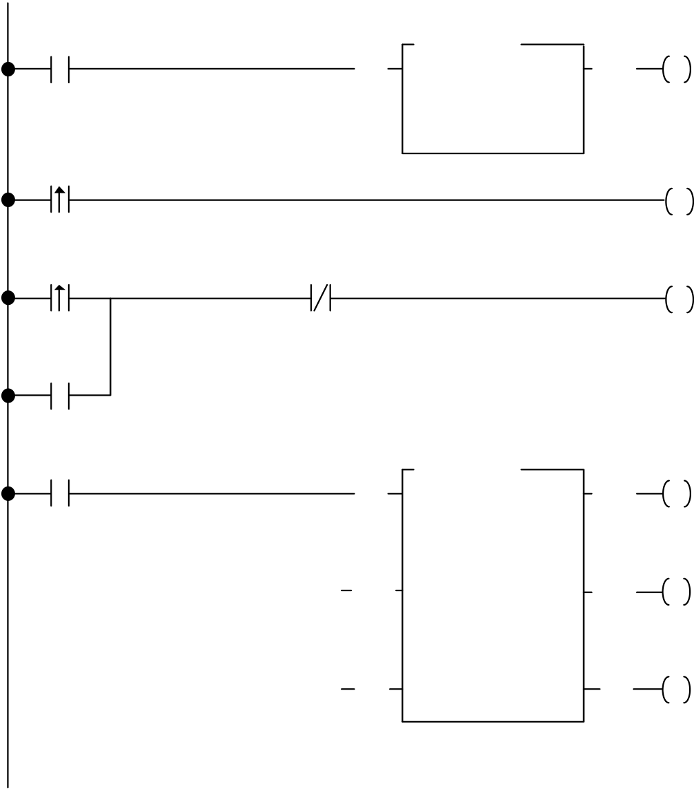
Program Example 3:Machine homing(by using Mode 2 of DRVZ command)
|
|
• M1924 initial/end pulse set the parameter of the servo parameter command into the |
system.
|
|
• Clears FUN140 homing completing signal. • Homing operation has started. • FUN140 operates DRVZ command. |

Servo Parameter Table(FUN141) Setting
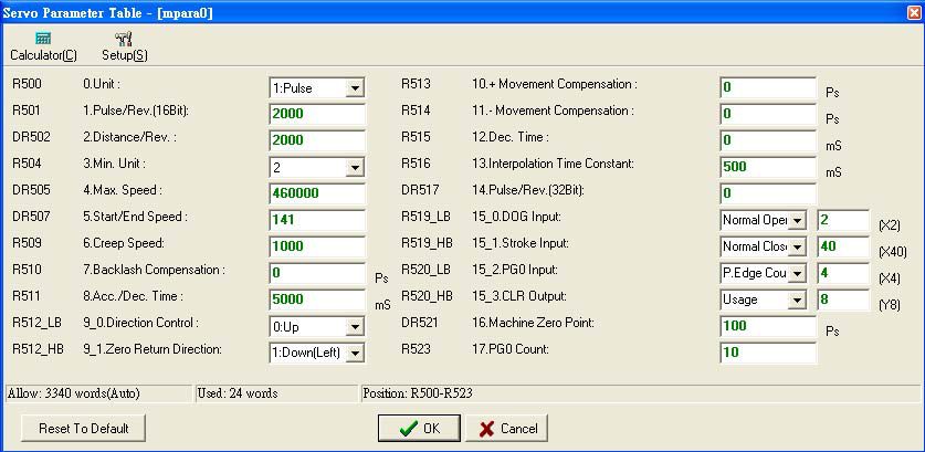
Servo Program Table(FUN140) Setting
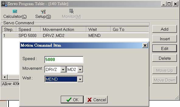
Program Description:
(1). When the program has been executed, the initial pulse (M1924) will set the starting address of servo parameters table.
(2). When M0 is from 0→1 (Pinstruction), the self-holding loop M1 has started and at the same time FUN140 homing operation has also started.
(3). According to FUN140 the servo program table setting, first the speed toward to homing return direction (left) is 5000 until it touches the DOG points (X2), it immediately drops the speed to 1000 and starts PG0 counting.
(4). When zero signal counting (X4) has reached its setting value 10, it finds the home position. Zero clear signal (Y8) sent to “ON” more than 20mS and as well as the machine zero position value, set to 100, moves to current register.
(In this example we use 0 axis, then set the value 100 to DR4088), then the homing operation has completed.




















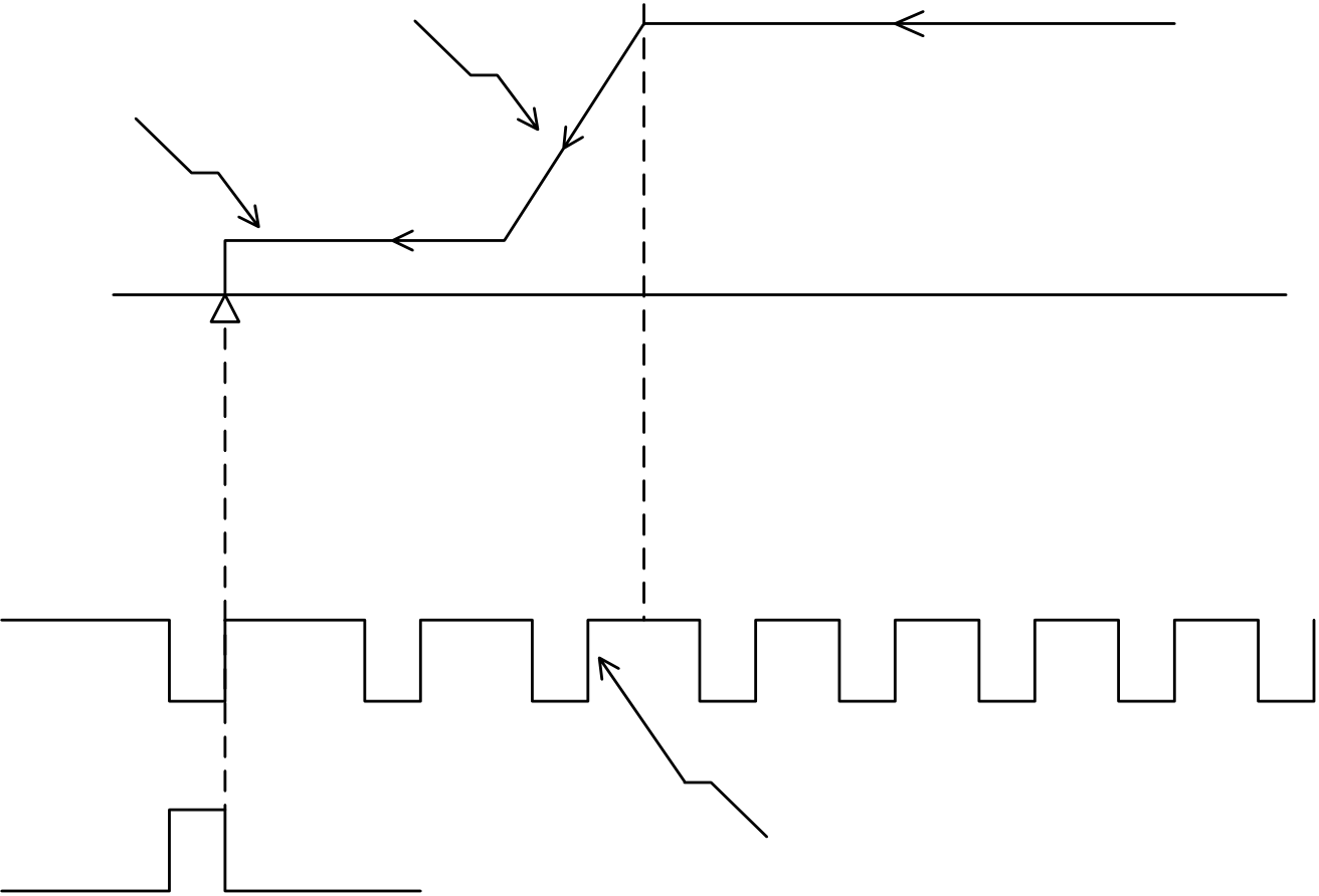
|
Diagram |
|
|
|
|
|
|
|
|
|
|
|
|
|
|
|
|
||||||||||
|
|
|||||||||||























※ When set the DOG point, it should be the input points (X0~X15) of main unit.
※ When the input DOG point has been set, it cannot be conflict with interrupt and high-speed counter, for example: if X0
has been set for DOG point, then X0 cannot be set to an interrupt input or high-speed counter.
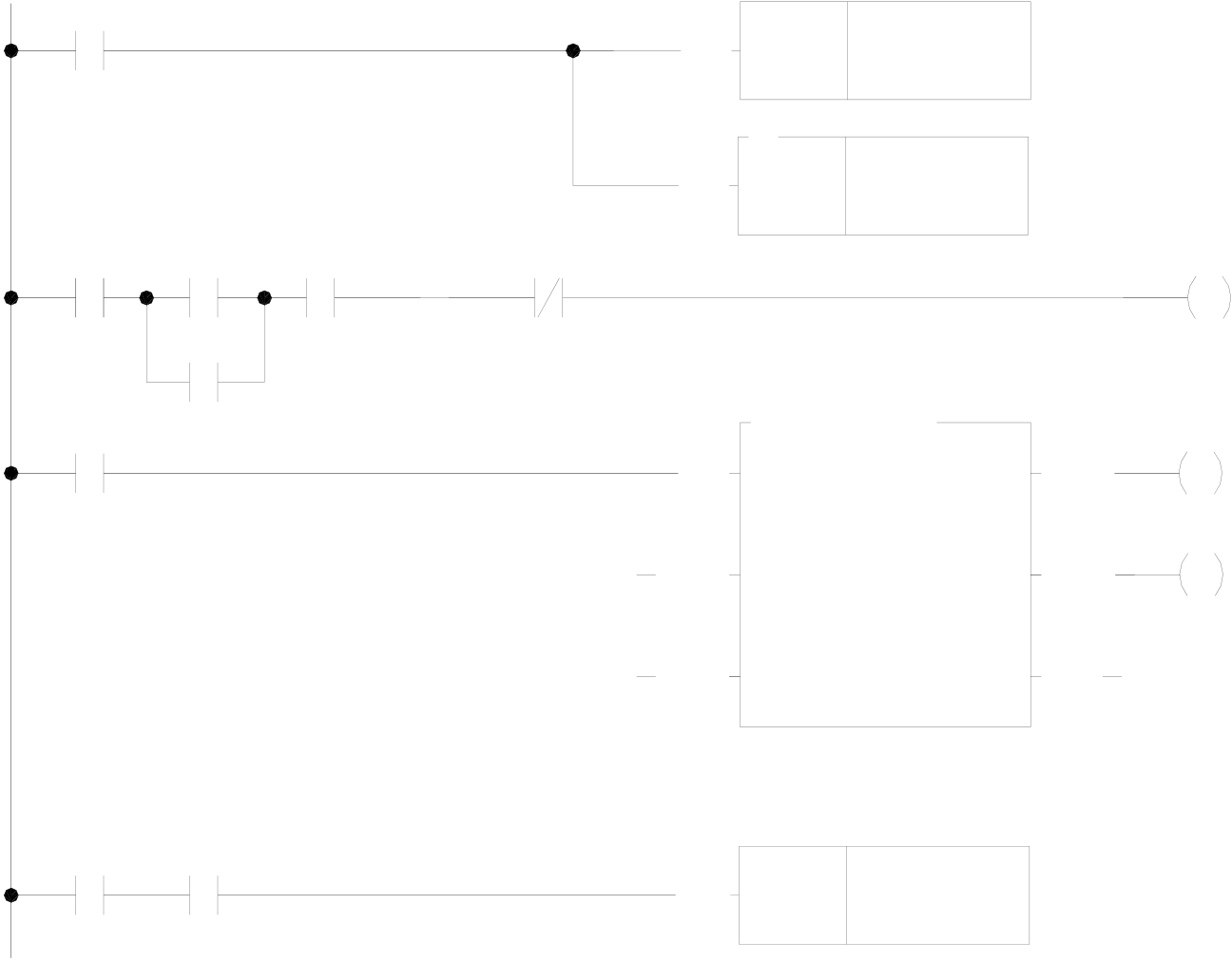
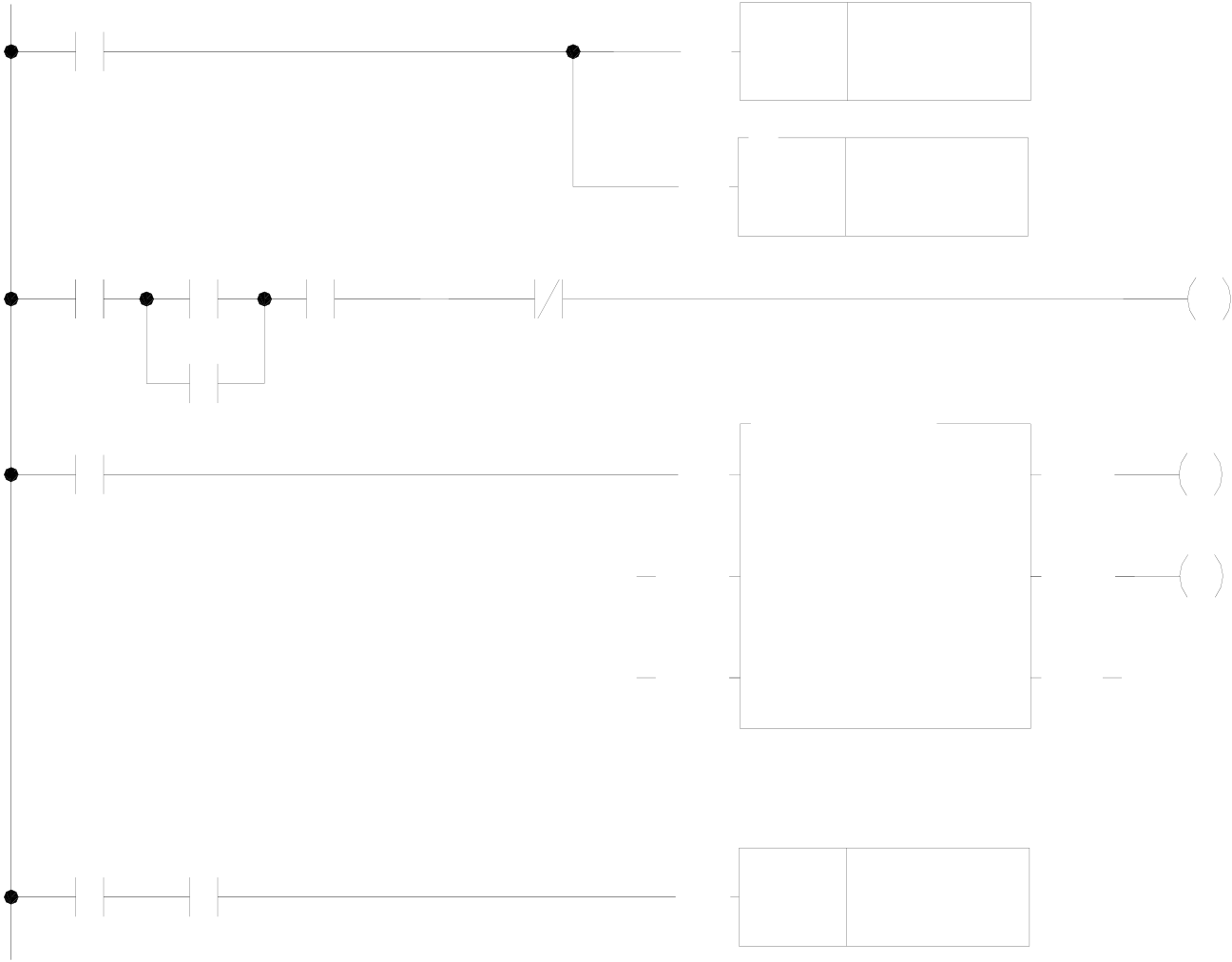
|
Program Example 4: JOG Forward |
|
Jog forward button |
M1 |
EN |
RST |
M1 |
M0 |
• Clears the completion signal |
||
|
↑ |
||||||||
|
Jog |
Servo |
Manaul |
D |
R 2000 |
• Starts from the first step every |
|||
|
EN |
||||||||
|
RST |
jog execution. |
|||||||
|
forward |
||||||||
|
button |
Ready |
operation |
||||||
M0
|
M0 |
Positioning program: |
EN |
140.HSPSO |
ACT |
M1000 |
|
|
Ps |
: 0 |
|||||
|
PAU |
SR |
: R 5000 |
ERR |
M1001 |
||
|
001 SPD 1000 |
WR |
: R 2000 |
||||
|
DRV ADR,+,1,Ps |
||||||
|
WAIT TIME,50 |
ABT |
DN |
||||
|
GOTO NEXT |
||||||
002 SPD R2907
DRV ADR,+,99999999,Ut
|
M0 |
MEND |
EN |
SET |
M1 |
• As the execution of last step |
|
M1996 |
completed, it sets up the |
||||
|
completion signal. |
|
Program Example 5: JOG Backward |
|
Jog backward button |
M3 |
EN |
RST |
M3 |
M2 |
• Clears the completion signal. |
|
|
↑ |
|||||||
|
Jog button Ready |
Manaul |
D |
R 2007 |
• Starts from the first step every |
|||
|
EN |
|||||||
|
RST |
jog execution. |
||||||
M2
|
M2 |
Positioning Program |
EN |
140.HSPSO |
ACT |
M1003 |
|
|
Ps |
: 0 |
|||||
|
PAU |
SR |
: R 5020 |
ERR |
M1004 |
||
|
001 SPD 1000 |
||||||
|
WR |
: R 2007 |
|||||
|
DRV ADR,−,1,Ps |
||||||
WAIT TIME,50
|
GOTO NEXT |
ABT |
DN |
|
002 SPD R2907 |
DRV ADR,−,99999999,Ut
MEND
|
M2 |
M1996 |
EN |
SET |
M3 |
• As the execution of the last step |
|
completed, it sets up the |
|||||
|
completion signal. |
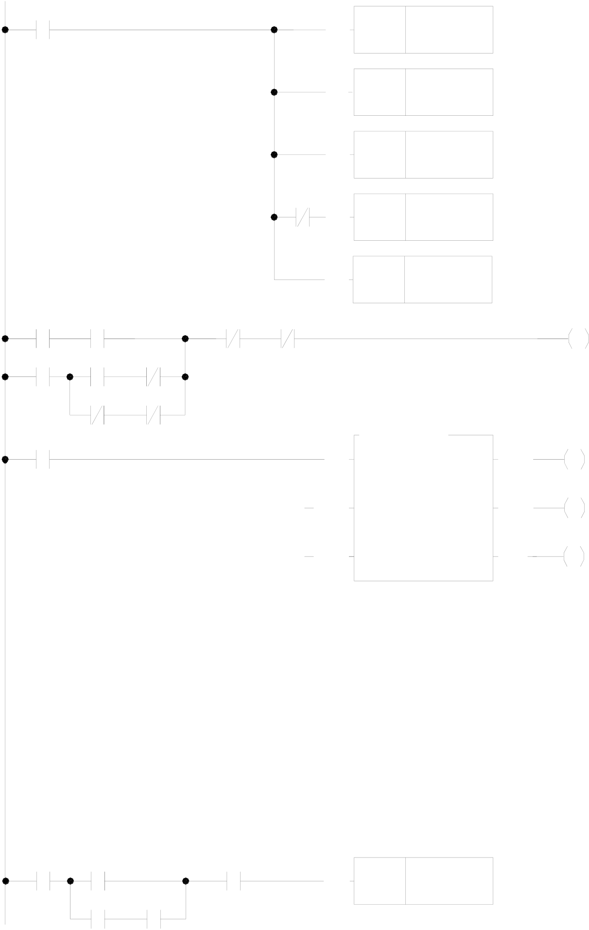
|
Program Example 6: Step by step, One cycle, Continuous positioning control. |
M93 : Start
M101 : Step by step operation mode
M102 : One cycle operation mode
M103 : Continuous operation mode
M104 : Regular shut down.
M105 : Emergency stop.
M93
|
↑ |
M101 |
EN |
RST |
M7 |
• Clears shut down signal. |
|
EN |
RST |
M1010 |
• Clears the error signal. |
||
|
EN |
RST |
M1011 |
• Clears the step completion signal. |
||
|
EN |
RST |
R 2021 |
|||
|
• Except step by step mode, the step |
|||||
|
pointer is cleared to be 0; it starts |
from the first step to execute.
|
M93 |
SERVO |
M105 |
M1010 |
EN |
RST |
R 2022 |
M6 |
• Clears being active bit of FUN140 |
|
READY |
↑
|
M6 |
M101 |
M1011 |
EN |
140.HSPSO |
ACT |
M1009 |
|
|
M6 |
M101 |
M7 |
|||||
|
Ps |
: 0 |
||||||
|
Positioning program: |
PAU |
SR |
: R 5100 |
ERR |
M1010 |
||
|
001 SPD 1000 |
WR |
: R 2021 |
|||||
|
DRV ADR,+,20000,Ut |
ABT |
DN |
M1011 |
||||
|
WAIT TIME,100 |
|||||||
|
GOTO NEXT |
|||||||
002 SPD 20000
DRV ADR,+,40000,Ut
WAIT M200
GOTO NEXT
003 SPD 25000
DRV ADR,−,50000,Ut
WAIT TIME,500
GOTO NEXT
004 SPD 5000
DRV ADR,−,10000,Ut
WAIT X16
GOTO 1
|
M6 |
M102 |
M104 |
M1996 |
EN |
SET |
M7 |
|
M103 |
• Set up the shut down signal.
Tip: press ← → to switch chapters, Ctrl+K to search