Module
In response to actual needs of user applications, FBs-PLC provides an economical combination of temperature and analog input module measurement. In short, it is to integrate single temperature module and the characteristics of analog input module. Therefore, the setup and operation methods for single temperature module and analog input module are exactly the same, except the number of channels can be measured is different. Both 2A4TC and 2A4RTD modules have offered 2 channels analog input and 4 channels temperature measurement capability. The difference is that 2A4TC is using thermocouple to measure temperature, while the 2ARTD4 is using RTD sensor to measure temperature. There are 8 types of thermocouple to choose: J、K、T、E、N、B、R、S; And there are only two types of RTD sensor: PT-100 and PT-1000.
This combination measurement module occupied 4 numerical input registers and 8 points digital output. The maximum measureable temperature point of a PLC main unit is 32 points. The update rate for temperature reading value can be set as normal (the resolution is 0.1°) or fast (the resolution is 1°).
The WinProladder provides the very user friendly table editing operation interface to configure the temperature measurement, for example, selecting the temperature module, type of sensor, and assign the registers to store the reading values. As to the temperature control, it has the convenient instruction FUN86 (TPCTL) to perform the PID operation to control the heating or cooling of the temperature process. Please refer to Chapter 18 for analog input operations and analog input modules setup.
21.1Specifications of Temperature and Analog Input Measuring Modules
21.1.1 Specifications of Temperature Measurement
|
Items Specifications Number of input points Thermocouple type and I/O Points Occupied Software Filter |
Module FBs-2A4TC 4 points J(−200~900°C) E(−190~1000°C) K(−190~1300°C) T(−190~380°C) R(0~1800°C) B(350~1800°C) S(0~1700°C) N(−200~1000°C) 2 IR(Input Register)、8 DO(Discrete Output) Moving Average |
Average Sample
Compensation
NO 1、2、4、8Configurable
Built-in cold junction compensation
Resolution 0.1°C
Conversion Time 2 or 4 seconds
Overall Precision ±(1%+1°C)
Isolation Transformer (Power) and photocouple (Signal) isolation (per-channel isolation)
|
Specifications |
Item |
Module |
|
FBs-2A4RTD |
||
|
RTD input points |
4 points |
3-wire RTD sensor JIS(α=0.00392) or DIN(α=0.00385)
RTD type and temperature measurement range
I/O Points Occupied
Pt-100(−200~850°C)
Pt-1000(−200~600°C)
2 IR(Input Register)、8 DO(Discrete Output)
|
Software Filter |
Moving Average 0.1°C 1 or 2 seconds Transformer(Power) and photocouple (Signal) isolation (pre-channel isolation) |
|
21.1.2 Specifications of Analog Input Measurement |
|
Specifications |
Item |
Module |
|
FBs-2A4TC/FBs-2A4RTD |
||
|
Input Channel |
2 Channel |
Digital input reading
−8192~+8191 or 0~16383(14-bit)
−2048~+2047 or 0~4095(12-bit)
|
Input signal types |
Voltage: -10~+10V, -5~+5V,0~5V,0~10V 2 IR(Input Register) |
Maximum absolute input signal
Voltage:±15V(max)
Current:±30mA(max)
Input resistance 63.2KΩ(Voltage Input)、250Ω(Current Input)
Isolation Transformer (Power) and photocouple (Signal)
21.1.3 Common Specifications
|
Specifications |
Item |
FBs-2A4TC |
Module |
|
FBs-2A4RTD |
|||
|
Internal Current Consumption |
5V, 50mA |
5V, 50mA |
|
|
External Current Consumption |
24V, 39mA |
24V, 39mA |
|
|
Indicator(s) |
5VPWR LED |
||
|
Operating Temperature |
0 ~ 60 ℃ |
||
|
Storage Temperature |
-20 ~ 80 ℃ |
||
|
Dimensions |
40(W)x90(H)x80(D) mm |
21.2The Procedures of Using Temperature Measurement
Please refer this part to section 20.2
21.3 The Procedures to Configure the Temperature Measurement
Please refer this part to section 20.3
21.4 Hardware Descriptions of Modules
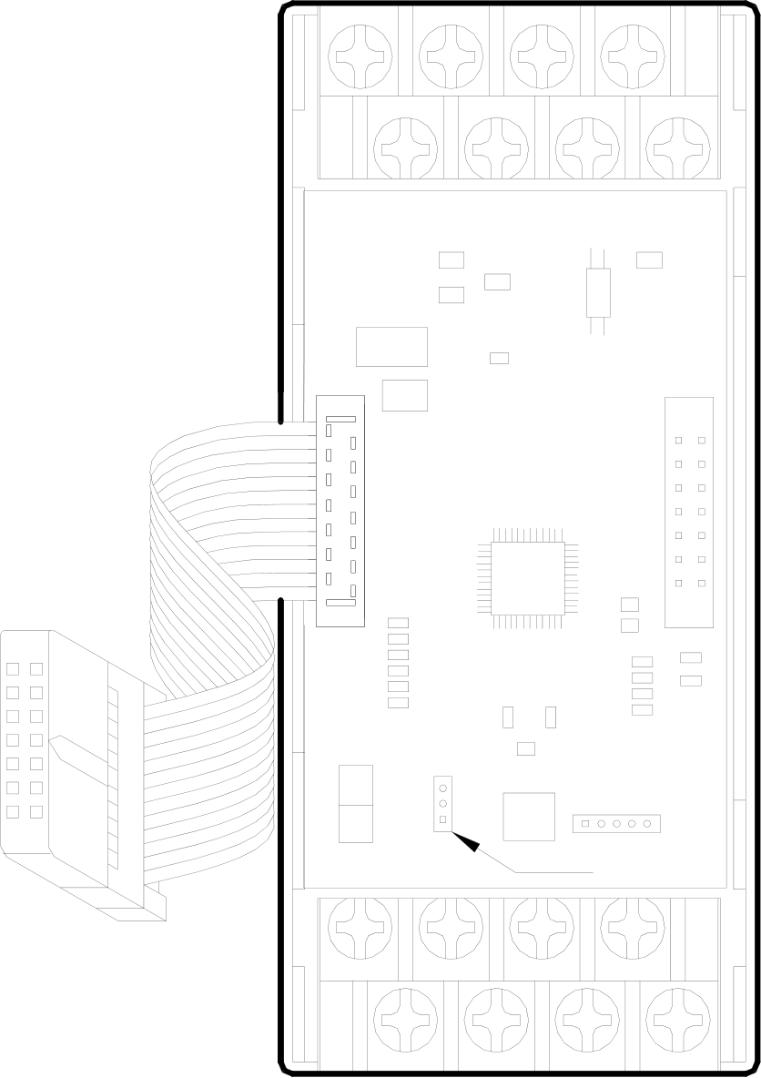
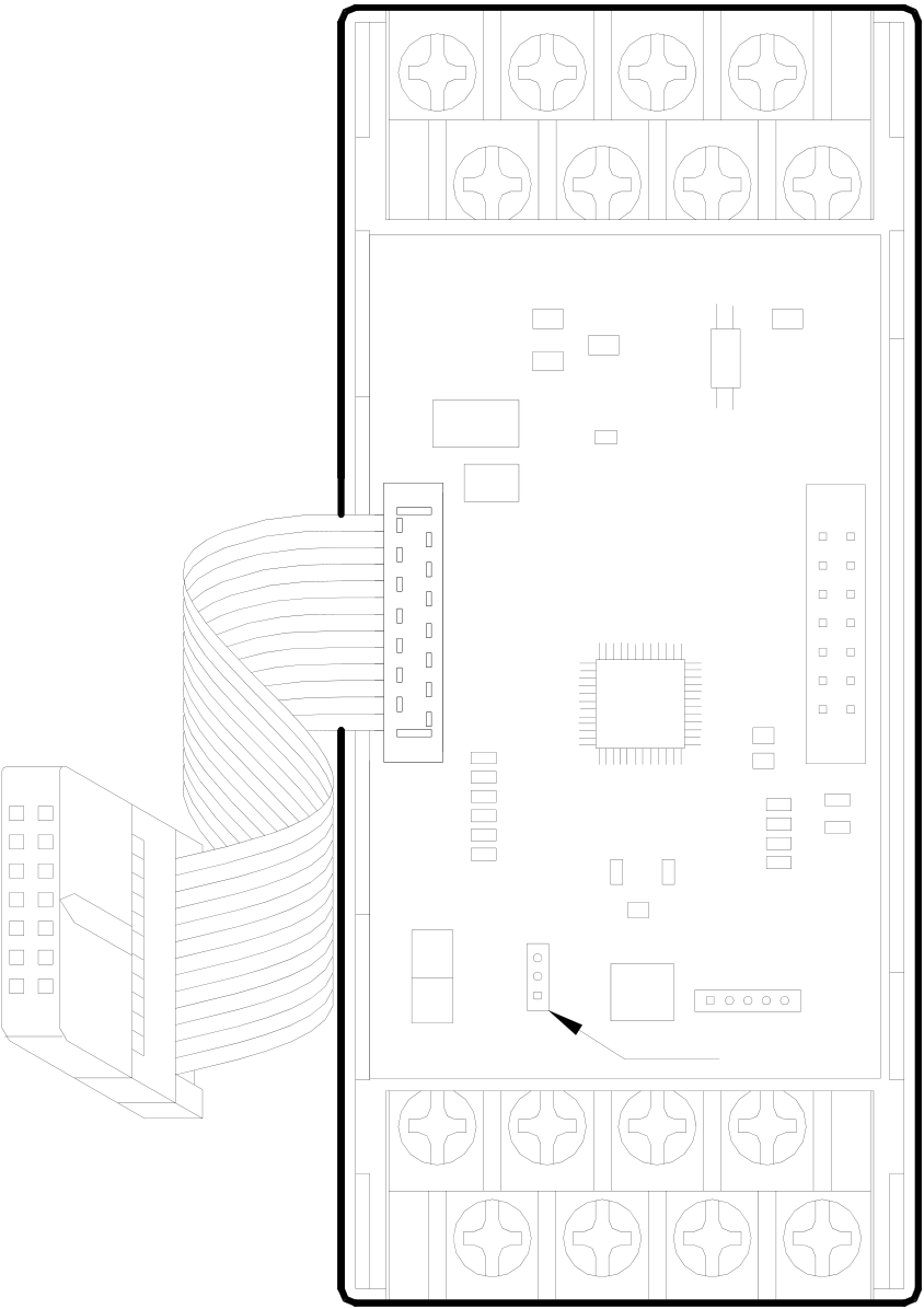
FBs-2A4TC and FBs-2A4RTD is composed by three circuit boards. The lowest layer is the power board (provides isolated power supply module), the medium is the I/O board (terminal blocks in this layer), the top layer is the control board (control and expand input and output connections). The description is as follows:
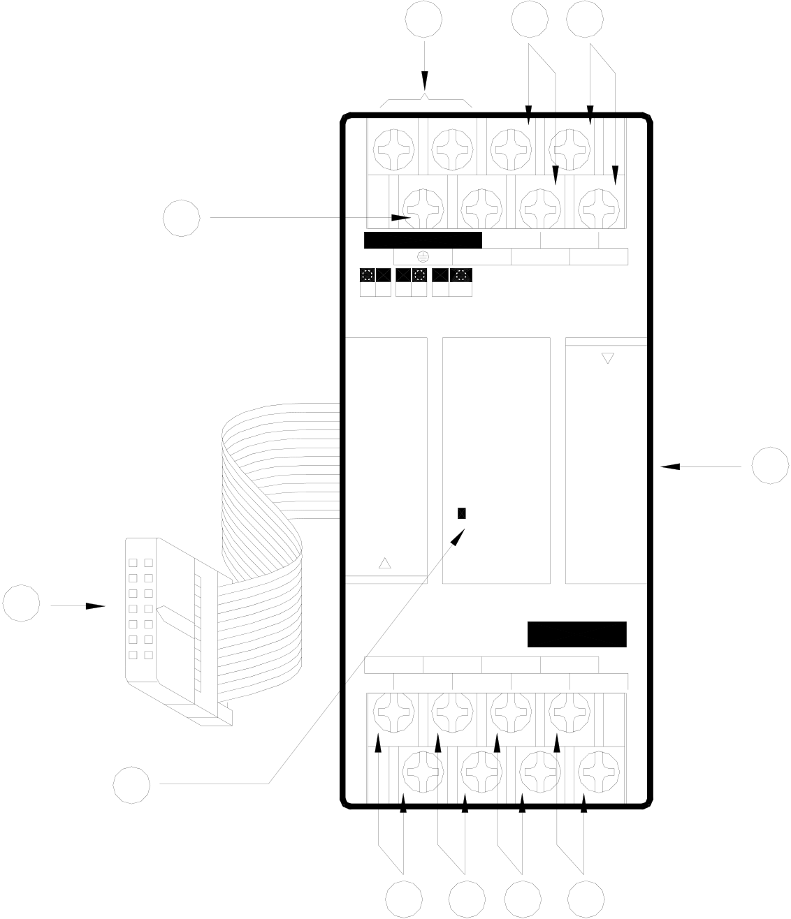
21.4.1 FBs-2A4TC/FBs-2A4RTD Outlook of Top View
2A4TC outlook of top view
|
2 |
1 |
AG |
6 |
7 |
|
+ 24V IN – |
||||
|
I0+ I1+ I0- I1- |
||||
|
V |
I |
U |
B |
5V |
10V |
4
POW
3
FBs-2A4TC
|
T0+ |
T0- |
T1+ |
T1- |
T2+ |
T2- |
T3+ |
T3- |
5
8 9 10 11
○1 External power input terminal:Power supply of analog circuit for this module, the voltage can be
24VDC±20%.
○2Protecting ground terminal:Connect to the shielding of signal cable.
○3 Expansion input cable:It should be connected to the front expansion unit, or the expansion output of main
unit.
○4 Expansion output connector:Provides the connection for next expansion unit.
○5 Power Indicator:It indicates whether the power supply of the analog circuit and external input power
source of this module are normal.
○6 Analog input terminal of CH0:The analog signal input of channel 0(I0+、I0-).
○7 Analog input terminal of CH1:The analog signal input of channel 1(I1+、I1-).
○8~○11 Thermocouple input terminal of CH0~CH3:The thermocouple input of channel 0~channel
3(T0+,T0-~T3+,T3-).
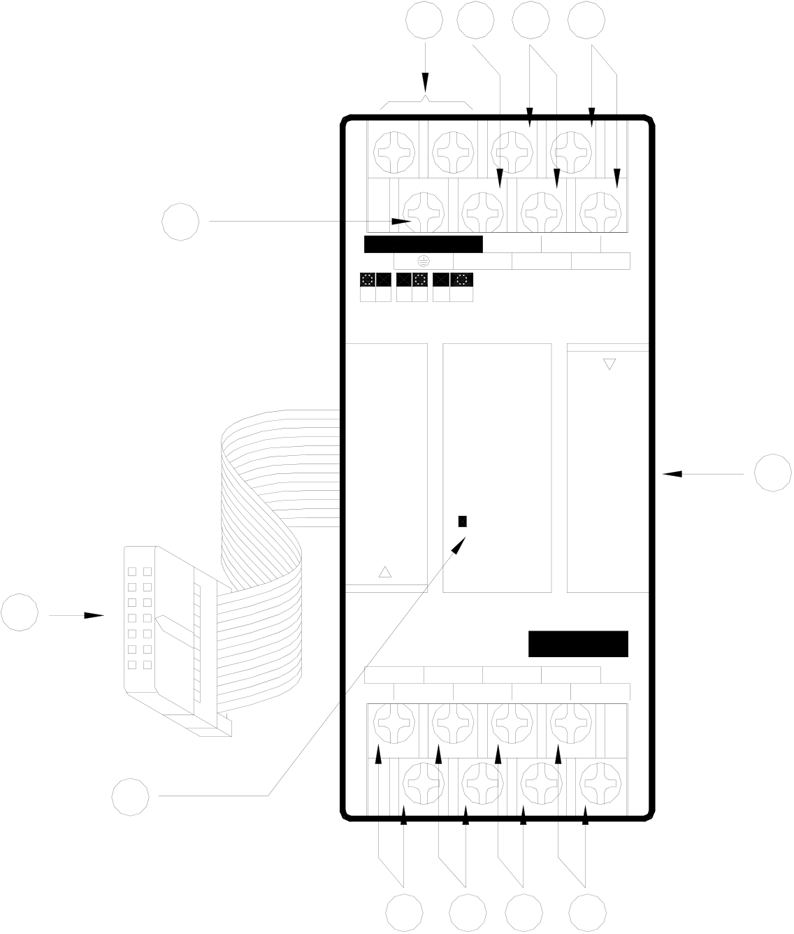
|
2A4RTD outlook of top view |
1 |
6 |
7 |
8 |
|
|
2 |
+ 24V IN – |
I0+ I1+ COM I0-I1- |
|||
|
VI |
UB |
5V |
10V |
4
POW
3
FBs-2A4RTD
|
P0+ |
P0- |
P1+ |
P1- |
P2+ |
P2- |
P3+ |
P3- |
5
9 10 11 12
○1 External power input terminal:Power supply of analog circuit for this module, the voltage can be
24VDC±20%.
○2Protecting ground terminal:Connect to the shielding of signal cable.
○3 Expansion input cable:It should be connected to the front expansion unit, or the expansion output of main
unit.
○4 Expansion output connector:Provides the connection for next expansion unit.
○5 Power indicator:It indicates whether the power supply of the analog circuit and external input power
source of this module are normal.
○6 Common terminals of RTD:To connect to the common wire of each 3-wires RTD input.
○7 Analog input terminal of CH0:The analog signal input of channel 0(I0+、I0-).
○8Analog input terminal of CH1:The analog signal input of channel 1(I1+、I1-).
○9~○12 Input terminal for CH0~CH3 RTD:The RTD input of channel0~channel3 (P0+,P0-~P3+,P3-).
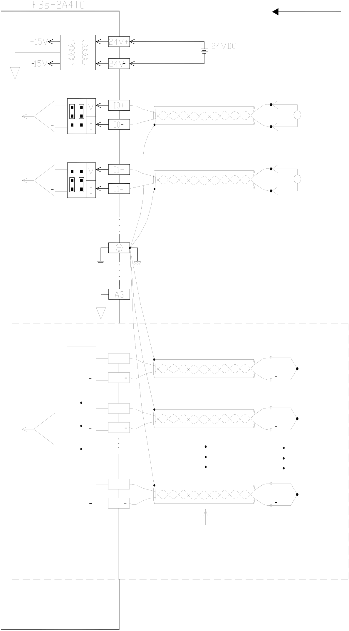
|
21.5Wiring of Modules 21.5.1 Wiring of 2A4TC Module |
Inputs
+
External power supply
|
+ |
+ |
T0+ |
Extension cable |
+ |
V |
CH0 Voltage Input |
|
+ |
I |
CH1 Current Input |
||||
|
Thermocouple |
T0
|
+ |
T1+ |
+ |
Thermocouple |
T1
Thermocouple
Input
|
+ |
T3+ |
+ |
Thermocouple |
T3
Multiplexer
Extension cable
(Shielding must be connected to FG)
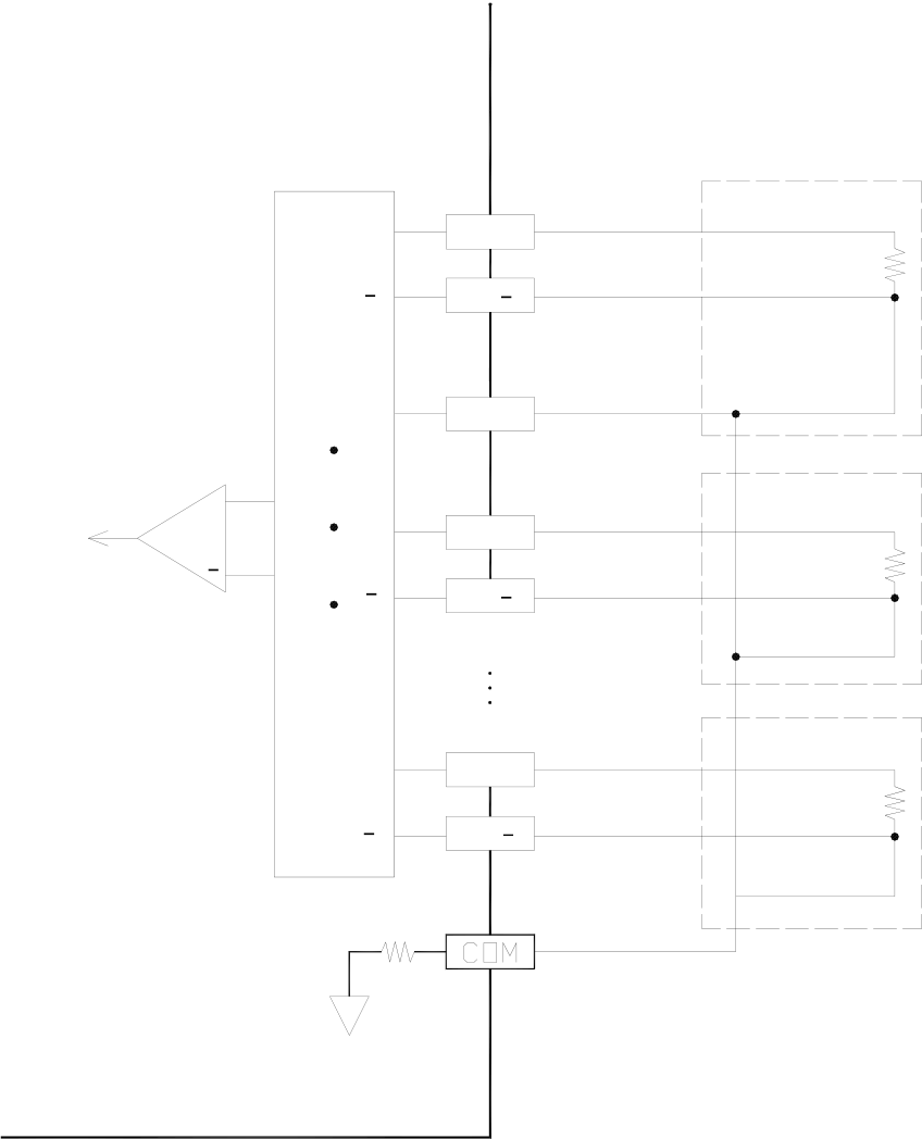
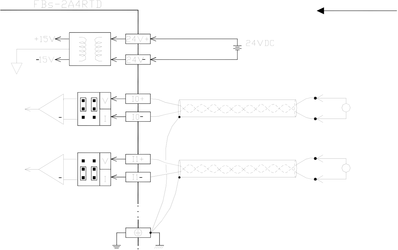
|
21.5.2 Wiring of 2A4RTD Module |
Inputs
+
External power supply
|
+ |
V |
CH0 Votage Input |
|
+ |
CH1 Current Input |
|
|
I |

|
+ |
+ |
P0+ |
Red line |
|
+ |
P0 |
White line |
|
|
White line |
|||
|
COM |
|||
|
Red line |
|||
|
P1+ |
|||
|
P1 |
White line |
White line
|
+ |
P3+ |
Red line |
|
P3 |
White line |
White line
Multiplexer
|
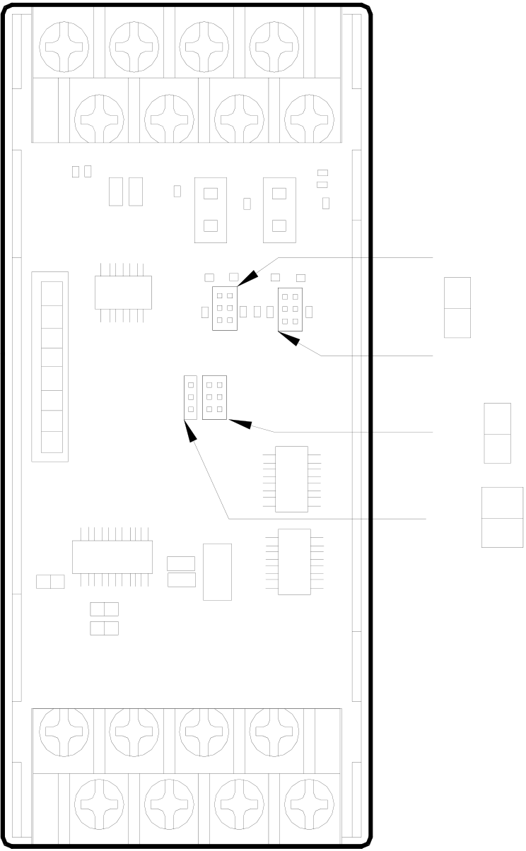
21.6 The Jumper Setup of 2A4RTD/2A4TC |
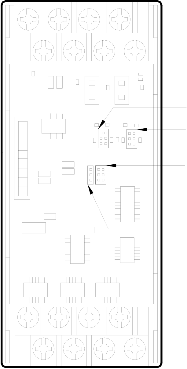
The analog input measurements of measurement signal and measurement range of these two modules are selected and set by the jumper’s connection
|
21.6.1 Position Jumper 21.6.1.1 The Position Jumper of 2A4TC |
JP3
V
I
JP4
|
JP5 JP6 |
U 10V |
U
B
JP1
Pin layout in control board(open top cover)
Pin layout on I/O board (remove control board)
|
21.6.1.2 The Position Jumper of 2A4RTD |
|||||||
|
B |
JP1 |
|
JP3 |
|
|||
|
JP4 |
|||||||
|
JP5 |
|
||||||
|
JP6 |
|
||||||
|
U |
|||||||
|
Pin layout in control board(open top cover) |
Pin layout on I/O board (remove control board) |
||||||
|
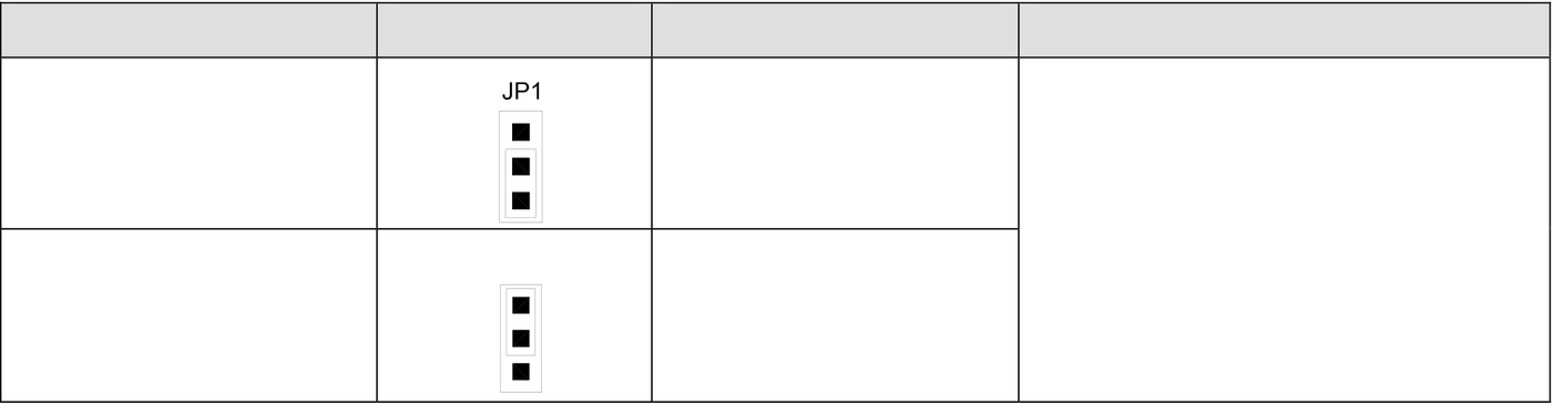
21.6.2 Input Code Format Selection of Jumper Setting |
|||||||
|
Input Code Format |
JP1 Setting |
Input Value Range |
Corresponding Input Signals |
||||
|
-10V~10V(-20mA~20mA) |
|||||||
|
Bipolar |
U |
-8192~8191 |
|||||
|
-5V~5V(-20mA~20mA) |
|||||||
B
|
Unipolar |
JP1 |
U |
0~16383 |
0V~10V(0mA~20mA) |
|
0V~5V(0mA~10mA) |
B
Regarding the explanations of choosing input code format, please refer to section 18.1.4.1.
|
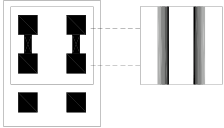
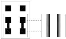
21.6.3 Input Signal Form of Jumper Setup |
|
Signal Form |
JP5 Setting |
JP6 Setting |
||||
|
0~10V |
|
|
||||
|
0~5V 0~10mA |
|
|||||
|
-10~+10V -20~+20mA |
|
|
||||
|
-5~+5V |
|




|
21.6.4 Input Signal Type of Jumper Setup |
|
Signal Form |
JP3(CH0) , JP4(CH1) Setting |
||
|
Voltage |
|
||
|
Current |
V |
||
|
I |
The default factory settings of FBs-2A4TC/FBs-2A4RTD are:
Input code format Æ Bipolar
Input signal type Æ -10V~+10V
For those applications that require the setting differ than the above default setting should make some modifications of jumper position according to above tables. While application, besides the setting of jumper should be conducted, the AI module configurations of Winproladder also need to be performed. (Refer to section 18.1.7 for explanation)
Tip: press ← → to switch chapters, Ctrl+K to search