









|
22.1Introduction of PID Control |
As the general application of process control, the open loop methodology may be good enough for most situations, because the key control elements or components are more sophisticated, and the performances of which are getting better, there is no doubt, the stability and reliability may meet the desired requirement. It is the way to get not bad C/P value with great economic consideration. But the characteristics of the elements or components may change following the time eclipse and the controlling process may be affected by the change of loading or external disturbances, the performance of open loop becomes looser; it is the weakness of such solution. Thus, closed loop (with the sensors to feedback the real conditions of controlling process for loop calculation) PID control is one of the best choices for manufacturing process to make perfect quantity and best products.
FBs-PLC provides digitized PID mathematical algorithm for general purpose application, it is enough for most of applications, but the response time of loop calculation will have the limitation by the scan time of PLC, thus it must be taken into consideration while in very fast closed loop control.
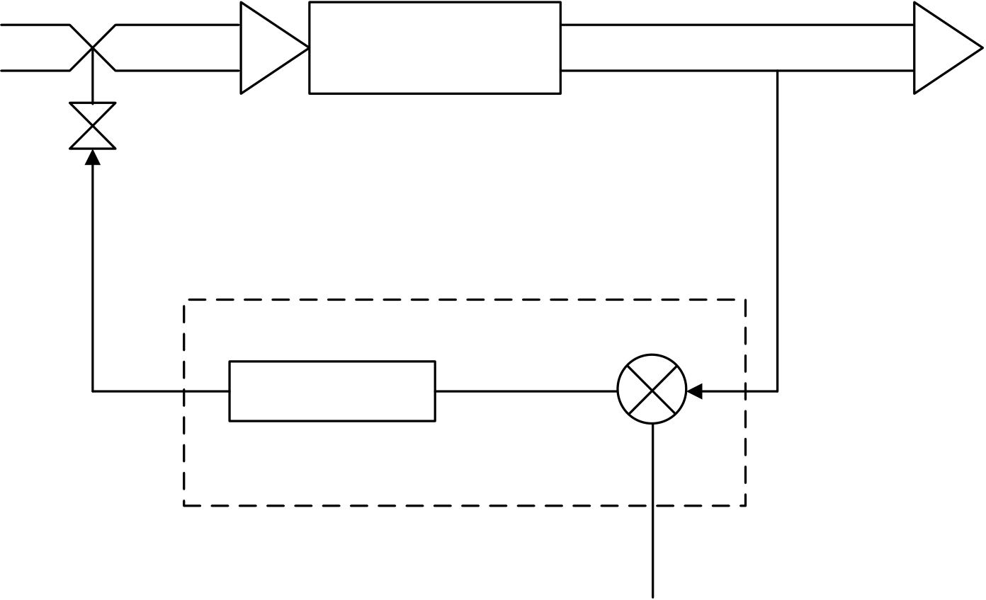
For an introduction to key parts of a control loop, refer to the block diagram shown below. The closed path around the diagram is the "loop" referred to in "closed loop control".




Typical Analog Loop Control System
|
22.2How to Select the Controller |
Depends on the requirement, the users may apply the suitable controller for different applications; it is much better of the thinking that the control algorithm is so simple and easy to operate and the final result will be good enough, that’s all. Therefore comes the answers, there are three types of controller could be activated from the PID mathematical expression, these are so called "Proportional Controller”, "Proportional + Integral Controller" and "Proportional + Integral + Derivative Controller". The digitized mathematical expression of each controller shown bellows.
|
22.2.1Proportional Controller |
The digitized mathematical expression as follows:
Mn = (D4005/Pb) × (En) + Bias
Where,
Mn :Output at time “n”.
D4005:The gain constant, the default is 1000, it’s range is 1~5000.
Pb :Proportional band
– the expression stating the percent change in error required to change the output full scale.
[Range:1~5000, unit in 0.1%;Kc(gain)=D4005/Pb]
En :The difference between the set point (SP) and the process variable (PV) at time "n"; En = SP – PVn
Ts :Solution interval between calculations(Range:1~3000, unit in 0.01S)
Bias :Offset to the output(Range:0~16383)
The algorithm of "Proportional Controller" is very simple and easy to implement, and it takes less time for loop calculation. Most of the general applications, this kind of controller is good enough, but it needs to adjust the offset (Bias)to the output to eliminate the steady state error due to the change of set point.
|
22.2.2Proportional + Integral Controller |
The digitized mathematical expression as follows:
|
n Mn =(D4005/Pb) × (En) +∑ |
[(D4005/Pb)×Ki×Ts×En] + Bias |
0
Where,
Mn : Output at time “n”.
D4005:The gain constant, the default is 1000, it’s range is 1~5000.
Pb : Proportional band [Range:1~5000,unit in 0.1%;Kc(gain)=D4005/Pb]En : The difference between the set point (SP) and the process variable (PV) at time "n"; En = SP – PVn
Ki : Integral tuning constant(Range:0~9999,it means 0.00~99.99 Repeats/Minute)Ts
: Solution interval between calculations(Range:1~3000, unit in 0.01S)Bias : Offset to the output(Range:0~16383)
The most benefit of the controller with integral item is to overcome the shortage of the "Proportional Controller" mentioned above; via the integral contribution, the steady state error may disappear, thus it is not necessary to adjust the offset manually while changing the set point. Almost, the offset(Bias)to the output will be 0.
|
22.2.3Proportional + Integral + Derivative Controller |
The digitized mathematical expression as follows:
n
Mn = (D4005/Pb) × (En) +∑ [(D4005/Pb)×Ki×Ts×En] − [(D4005/Pb)×Td×(PVn−PVn-1)/Ts] + Bias
0
Where,
Mn :Output at time “n”.
D4005:The gain constant, the default is 1000, it’s range is 1~5000.
Pb :Proportional band [Range:1~5000,unit in 0.1%;Kc(gain)=D4005/Pb]
En : The difference between the set point (SP) and the process variable (PV) at time "n";
En = SP – PVn
Ki : Integral tuning constant(Range:0~9999,it means 0.00~99.99 Repeats/Minute)
Td :Derivative tuning constant (Range:0~9999,it means 0.00~99.99 Minute)
PVn : Process variable at time “n”
PVn-1: Process variable when loop was last solved
Ts :Solution interval between calculations(Range:1~3000, unit in 0.01S)
Bias :Offset to the output(Range:0~16383)
Derivative item of the controller may have the contribution to make the response of controlling process smoother
and not too over shoot. But because it is very sensitive of the derivative contribution to the process reaction, most of
applications, it is not necessary of this item and let the tuning constant (Td) be equal to 0.
22.3Explanation of the PID Instruction and Example Program Follows
The followings are the instruction explanation and program example for PID (FUN30) loop control of FBs-PLC.

|
FUN 30 PID |
Convenient Instruction of PID Loop Operation |
FUN 30 PID |
|||||||||||||||||||||||||||||||||||||||||||||||||||||||||||||||||||||||||||||||||||||||||
it takes 7registers.
|
|||||||||||||||||||||||||||||||||||||||||||||||||||||||||||||||||||||||||||||||||||||||||||
|
● The FBs-PLC software algorithm uses mathematical functions to simulate a three-mode (PID) analog controlling technique to provide direct digital control. The control technique responds to an error with an output signal. The output is proportional to the error, the error’s integral and the rate of change of the process variable. Control algorithms include, P, PI, PD and PID which all include the features of auto/manual operation, bumpless/balanceless transfers, reset wind-up protection, and adaptive tuning of gain, integral, and derivative terms. ● The digitized mathematical expression of FBs-PLC PID instruction as bellows: n Mn = (D4005/Pb) × (En) +∑ [(D4005/Pb)×Ki×Ts×En] − [(D4005/Pb)×Td×(PVn−PVn-1)/Ts] + Bias 0 Where, Mn : Output at time “n” D4005 : The gain constant, the default is 1000, which can be set between 1~5000. Pb : Proportional band – the expression stating the percent change in error required to change the output full scale. [Range:1~5000,unit in 0.1%;Kc(gain)=D4005/Pb] Ki : Integral tuning constant (Range:0~9999,it means 0.00~99.99 Repeats/Minute) Td : Derivative tuning constant (Range:0~9999,it means 0.00~99.99 Minute) PVn : Process variable at time “n” PVn-1 : Process variable when loop was last solved En : The difference between the set point (SP) and the process variable (PV) at time "n"; En = SP – PVn Ts : Solution interval between calculations(Range:1~3000, unit in 0.01S) Bias : Offset to the output(Range:0~16383) |
|||||||||||||||||||||||||||||||||||||||||||||||||||||||||||||||||||||||||||||||||||||||||||
|
FUN30 PID |
Convenient Instruction of PID Loop Operation |
FUN30 PID |
||
|
Principle of PID parameter adjustment zAs the proportional band (Pb) adjustment getting smaller, the larger the proportional contribution to the output. This can obtain a sensitive and rapid control reaction. However, when the proportional band is too small, it may cause oscillation. Do the best to adjust “Pb” smaller (but not to the extent of making oscillation), which could increase the process reaction and reduce the steady state error. zIntegral item may be used to eliminate the steady state error. The larger the number (Ki, integral tuning constant), the larger the integral contribution to the output. When there is steady state error, adjust the “Ki” larger to decrease the error. When the “Ki” = 0, the integral item makes no contribution to the output. For ex, if the reset time is 6 minutes, Ki=100/6=17;if the integral time is 5 minutes, Ki=100/5=20. zDerivative item may be used to make the process smoother and not too over shoot. The larger the number (Td, derivative tuning constant), the larger the derivative contribution to the output. When there is too over shoot, adjust the “Td” larger to decrease the amount of over shoot. When the “Td” = 0, the derivative item makes no contribution to the output. For ex, if the rate time is 1 minute, then the Td = 100; if the rate time is 2 minutes, then the Td = 200. zProperly adjust the PID parameters can obtain an excellent result for loop control.
z When control input "A/M"=0, it performs manual control and will not execute the PID calculation. Directly fill the output value into the output register (OR) to control the loop operation. z When control input "A/M"=1, it defines the auto mode of loop control; the output of the loop operation is loaded by the PID instruction every time it is solved. It is equal to Mn (control loop output) in the digital approximation equation. z When control input "BUM"=1, it defines bumpless transfer while the loop operation changing from manual into auto mode. z When control input "A/M"=1, and direction input "D/R"=1, it defines the direct control for loop operation; it means the output increases as error increases z When control input "A/M"=1, and direction input "D/R"=0, it defines the reverse control for loop operation; it means the output decreases as error increases z When comes the error setting of loop setting points or loop parameters, the PID operation will not be performed and the output indication "ERR" will be ON z While the engineering value of the controlling process is greater than or equal to the user set High Limit, the output indication "HAL" will be ON regardless of "A/M" state. z While the engineering value of the controlling process is less than or equal to the user set Low Limit, the output indication "LAL" will be ON regardless of "A/M" state. |
||||
|
FUN30 PID |
Convenient Instruction of PID Loop Operation |
FUN30 PID |
|||
|
● Description of operand Ts: zTs:It defines the solution interval between PID calculations, the unit is in 0.01 sec; this term may be constant or variable data. ● Description of operand SR (Loop setting registers): zSR+0 = Scaled Process Variable:This register is loaded by the PID instruction every time it gets solved. A linear scaling is done on SR+6 using the high and low engineering range found in SR+4 and SR+5. zSR+1 = Setpoint (SP) :The user must load this register with the desired setpoint the loop should control at. The setpoint is entered in engineering units, it must be the range:LER ≦ SP ≦ HER zSR+2 = High Alarm Limit (HAL): The user must load this register with the value at which the process variable should be alarmed as a high alarm (above the setpoint). This value is entered as the actual alarm point in engineering units and it must be the range:LER ≦ LAL < HAL ≦ HER zSR+3 = Low Alarm Limit (LAL): The user must load this register with the value at which the process variable should be alarmed as a low alarm (below the setpoint). This value is entered as the actual alarm point in engineering units and it must be the range:LER ≦ LAL < HAL ≦ HER
which the measurement device is spanned. (For example a thermocouple might be spanned for 0 to 500 degrees centigrade, resulting in a 0 to 10V analog input to the FBs-PLC (0V=0℃, 10V=500℃); the high engineering range is 500, this is the value entered into SR+4.) zSR+5 = Low Engineering Range (LER):The user must load this register with the lowest value for which the measurement device is spanned. The low engineering range must be:−9999 ≦ LER ≦ LAL < HAL ≦ HER zSR+6 = Raw Analog Measurement (RAM):The user’s program must load this register with the process variable (measurement). It is the value that the content of analog input register(R3840~R3903)is added by the offset if necessary. It must be the range:0 ≦ RAM ≦ 16380 if the analog input is 14-bit format but valid 12-bit resolution, and 0 ≦ RAM ≦ 16383 if the analog input is 14-bit format and valid 14-bit resolution. The resolution of analog input can be defined by register D4004, zSR+7 = Offset of Process Variable (OPV):The user must load this register with the value as described follows: OPV must be 0 if the raw analog signal and the measurement span of the analog input module are all 0~20mA, there is no loss of the measurement resolution; OPV must be 3276 if the raw analog signal is 4~20mA but the measurement span of the analog input module is 0~20mA, there will have few loss of the measurement resolution(16383×4 / 20 = 3276). It must be the range: 0 ≦ OPV < 16383 z When the setting mentioned above comes error, it will not perform PID operation and the output indication "ERR" will be ON. ● Description of operand OR: zOR:Output register, this register is loaded directly by the user while the loop in manual operation mode. While the loop in auto operation mode, this register is loaded by the PID instruction every time it is solved. It is equal to Mn (control loop output) in the digital approximation equation. It must be the range:0 ≦ OR ≦ 16383 |
|||||
|
FUN 30 PID |
Convenient Instruction of PID Loop Operation |
FUN 30 PID |
|
● Description of operand PR (Loop parameters): zPR+0 = Proportional Band (Pb):The user must load this register with the desired proportional constant. The proportion constant is entered as a value between 1 and 5000 where the smaller the number, the larger the proportional contribution. (This is because the equation uses D4005 divided by Pb.) zPR+1 = Integral tuning Constant (Ki):The user may load this register to add integral action to the calculation. The value entered is "Repeats/Minute" and is entered as a number between 0 and 9999. (The actual range is 00.00 to 99.99 Repeats/Minute.) The larger the number, the larger the integral contribution to the output. It must be the range:0 ≦ Ki ≦ 9999 (0.00~99.99 Repeats/Minute) zPR+2 = Rate Time Constant (Td):The user may load this register to add derivative action to the calculation. The value is entered as minutes and entered as a number between 0 and 9999. (The actual range is 0.00 to 99.99 minutes.) The larger the number, the larger the derivative contribution to the output. It must be the range:0 ≦ Td ≦ 9999 (0.00~99.99 Minutes) zPR+3 = Bias:The user may load this register if a bias is desired to be added to the output when using PI or PID control. A bias must be used when running proportional only control. The bias is entered as a value between 0 and 16383 and is added directly to the calculated output. Bias is not required for most applications and may be left at 0. It must be the range:0 ≦ Bias ≦ 16383 zPR+4 = High Integral Wind_up Limit (HIWL):The user must load this register with the output value, (1 to 16383), at which the loop shoud go into "anti-reset wind-up" mode. Anti-reset wind-up consists of solving the digital approximation for the integral value. For most applications this should be set to 16383. It must be the range:1 ≦ HIWL ≦ 16383 zPR+5 = Low Integral Wind_up Limit (LIWL):The user must load this register with the output value, (0 to 16383), at which the loop shoud go into "anti-reset wind-up" mode. It functions in the same manner as PR+4. For most applications this should be set to 0. It must be the range:0 ≦ LIWL ≦ 16383 zPR+6 = PID Method: The user may try method 1 when using PID control and the result is not stable. zWhen the setting mentioned above comes error, it will not perform PID operation and the output indication "ERR" will be ON. |
||

|
FUN 30 |
Convenient Instruction of PID Loop Operation |
FUN 30 |
|
|
● |
Description of operand WR (Working registers): |
||
zWR+0 = Loop status register:
Bit0 =0 , Manual operation mode
=1 , Auto mode
Bit1 : This bit will be a 1 during the scan the solution is being solved, and it is ON for a scan time.
Bit2=1 , Bumpless transfer
Bit4 : The status of "ERR" indication
Bit5 : The status of "HAL" indication
Bit6 : The status of "LAL" indication
z WR+1 = Loop timer register:This register stores the cyclic timer reading from the system’s 1ms cyclic timer each time the loop is solved. The elapsed time is calculated by calculating the difference between the current reading of the system’s 1ms cyclic timer and the value stored in this register. This difference is compared to 10× the solution interval. If the difference is greater than or equal to the solution interval, the loop should be solved this scan.
z WR+2 = Low order integral summation:This register stores the low order 16 bits of the 32-bit sum created by the integral term.
z WR+3 = High order integral summation:This register stores the high order 16 bits of the 32-bit sum created by the integral term.
z WR+4 = Process variable – previous solution:The raw analog input (Register SR+6) at the time the loop was last sovled. This is used for the derivative control mode.
Program example
z Adding the content of analog input register with the offset
|
R2000 and stores it into R1006 being as the raw analog |
EN |
11.(+) |
D=0 |
Y0 |
||
|
input of PID instruction. |
Sa |
: R3840 |
||||
|
z When the value of R3840 is -8192~8191, the value of |
U/S |
Sb |
: R2000 |
CY |
||
|
D |
: R1006 |
|||||
|
R2000 must be 8192 ; the value of R3840 is 0~16383, |
BR |
|||||
|
then the value of R2000 must be 0. |
||||||
|
30.PID |
||||||
|
M0 |
||||||
|
z X0=0,Manual operation |
A/M |
Ts |
: R999 |
ERR |
Y1 |
|
|
SR |
: R1000 |
|||||
|
=1,Auto operation |
BUM |
OR |
: R1010 |
HAL |
||
|
Y2 |
||||||
|
Pr |
: R1020 |
|||||
|
D/R |
WR |
: R1030 |
LAL |
|||
12.(-)
|
z R1010 is the output of PID instruction. |
EN |
Sa |
: R1010 |
D=0 |
|
Sb |
: R2001 |
CY |
||
|
z Deducting the offset R2001 from the output value |
U/S |
D |
: R3904 |
|
|
BR |
||||
|
and stores it into the analog output register for analog |
output.
z If the output value of R3904 is 0~16383, the value of
R2001 must be 0 ; If the value of R3904 is -8192~8191,
the value of R2001 must be 8192.
|
FUN 30 PID |
Convenient Instruction of PID Loop Operation |
FUN 30 PID |
||||||
R1003 :The setting of low alarm limit; which is entered in
is 0°C.
R1007 :Offset of process variable; let it be 0 if the raw |
||||||||
Tip: press ← → to switch chapters, Ctrl+K to search