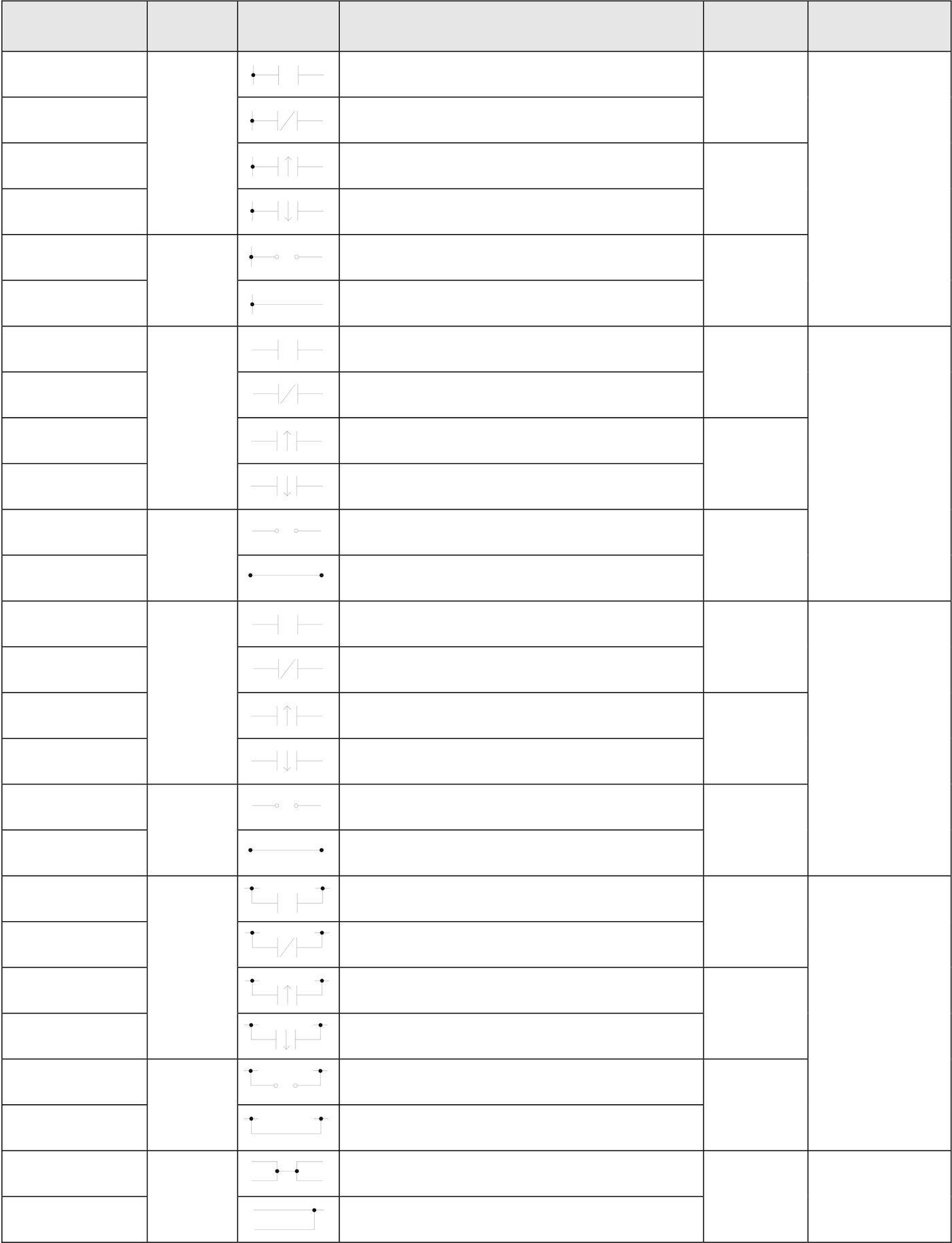
3.1 Sequential Instructions
|
Instruction |
Operand |
Symbol |
Function Descriptions |
Execution |
Instruction type |
||||
|
Time |
|||||||||
|
ORG |
X,Y,M, |
Starting a network with a normally open (A) |
0.33uS |
Network |
|||||
|
contact |
|||||||||
|
ORG NOT |
Starting a network with a normally closed |
||||||||
|
(B) contact |
|||||||||
|
S,T,C |
Starting a network with a differential up |
||||||||
|
ORG TU |
0.54uS |
||||||||
|
(TU) contact |
|||||||||
|
starting |
|||||||||
|
ORG TD |
Starting a network with a differential down |
||||||||
|
instructions |
|||||||||
|
(TD) contact |
|||||||||
|
ORG OPEN |
X,Y,M, |
0.33uS |
Origin or |
||||||
|
Starting a network with a open circuit |
|||||||||
|
contact |
|||||||||
|
ORG SHORT |
Starting a network with a short circuit |
||||||||
|
contact |
|||||||||
|
LD |
Starting a relay circuit from origin or branch |
0.33uS |
|||||||
|
line with a normally open contact |
|||||||||
|
LD NOT |
Starting a relay circuit from origin or branch |
||||||||
|
line with a normally closed contact |
|||||||||
|
LD TU |
S,T,C |
Starting a relay circuit from origin or branch |
0.54uS |
||||||
|
line with a differential up contact |
branch line |
||||||||
|
LD TD |
Starting a relay circuit from origin or branch |
starting |
|||||||
|
line with a differential down contact |
|||||||||
|
instructions |
|||||||||
|
LD OPEN |
Starting a relay circuit from origin or branch |
0.33uS |
|||||||
|
line with a open circuit contact |
|||||||||
|
LD SHORT |
Starting a relay circuit from origin or branch |
||||||||
|
line with a short circuit contact |
|||||||||
|
AND |
X,Y,M, |
Serial connection of normally open contact |
0.33uS |
Serial |
|||||
|
Serial |
connection |
of |
normally |
closed |
|||||
|
AND NOT |
|||||||||
|
contact |
|||||||||
|
AND TU |
S,T,C |
Serial connection of differential up contact |
|||||||
|
AND TD |
Serial connection of differential down |
0.54uS |
connection |
||||||
|
contact |
instructions |
||||||||
|
AND OPEN |
Serial connection of open circuit contact |
||||||||
0.33uS
|
AND SHORT |
X,Y,M, |
Serial connection of short circuit contact |
0.33uS |
Parallel |
||||
|
OR |
Parallel |
connection |
of |
normally |
open |
|||
|
contact |
||||||||
|
OR NOT |
Parallel connection of normally closed |
|||||||
|
contact |
||||||||
|
OR TU |
S,T,C |
Parallel connection of differential up contact |
0.54uS |
|||||
|
connection |
||||||||
|
OR TD |
Parallel connection of differential down |
|||||||
|
contact |
instructions |
|||||||
|
OR OPEN |
Parallel connection of open circuit contact |
|||||||
0.33uS
|
OR SHORT |
Parallel connection of short circuit contact |
0.33uS |
Blocks merge |
|
Serial connection of two circuit blocks |
|||
|
ANDLD |
|||
|
ORLD |
Parallel connection of two circuit blocks |
instructions |
|
Instruction |
Operand |
Symbol |
Function Descriptions |
Execution |
Instruction type |
|
Time |
|||||
|
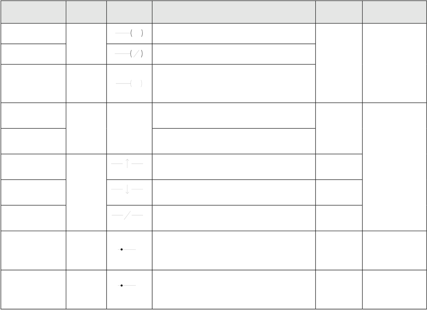
OUT |
Y,M,S |
L |
Send result to coil |
0.33uS |
Coil output |
|
OUT NOT |
Send inverted result to coil |
||||
|
│ |
|||||
|
Y |
instruction |
||||
|
Send result to an external output coil and |
|||||
|
OUT |
1.09uS |
||||
|
appoint it as of retentive type |
|||||
|
OUT L |
TR |
Save the node status to a temporary relay |
0.33uS |
Node operation |
|
|
LD |
Load the temporary relay |
||||
|
TU |
Take the transition up of the node status |
0.33uS |
|||
|
instruction |
|||||
|
TD |
Take the transition down of the node status |
0.33uS |
|||
|
NOT |
Invert the node status |
0.33uS |
0.33uS
|
SET |
( |
S |
) |
Set a coil |
│ |
1.09uS
|
RST |
( |
R |
) |
Reset a coil |
0.33uS |
|
│ |
1.09uS
●The 36 sequential instructions listed above are all applicable to every models of FBs-PLC.
3.2 Function Instructions
There are more than 100 different FBs-PLC function instructions. If put the D and P derivative instructions into account, the total number of instructions is over 300. On top of these, many function instructions have multiple input controls (up to 4 inputs) which can have up to 8 different types of operation mode combinations. Hence, the size of FBs-PLC instruction sets is in fact not smaller than that of a large PLC. Having powerful instruction functions, though may help for establishing the complicated control applications, but also may impose a heavy burden on those users of small type PLC’s. For ease of use, FATEK PLC function instructions are divided into two groups, the Basic function group which includes 26 commonly used function instructions and 4 SFC instructions and the advanced function group which includes other more complicated function instructions, such as high-speed counters and interrupts. This will enable the beginners and the non-experienced users to get familiar with the basic function very quickly and to assist experienced users in finding what they need in the advanced set of function instructions.
The instructions attached with “” symbol are basic functions which amounts to 26 function instructions and 4 SFC instructions. All the basic functions will be explained in next chapter. The details for the reset of functions please refer advanced manual.
|
|
General Timer/Counter Function Instructions |
|
FUN No. |
Name |
Operand |
Derivative Instruction |
Function descriptions |
|
T nnn |
PV |
General timer instructions (“nnn” range 0~255, total 256) |
||
|
C nnn |
PV |
General counter instructions (“nnn” range 0~255, total 256) |
||
|
7 |
UDCTR |
CV,PV |
DP |
16-Bit or 32-Bit up/down counter |
|
|
Single Operand Function Instructions |
|
4 |
DIFU |
D |
P |
To get the up differentiation of a D relay and store the result to D |
|
5 |
DIFD |
D |
P |
To get the down differentiation of a D relay and store the result to D |
|
10 |
TOGG |
D |
P |
Toggle the status of the D relay |
|
|
Setting/Resetting |
|
SET |
D |
DP |
Set all bits of register or a discrete point to 1 |
|
|
RST |
D |
DP |
Clear all bits of register or a discrete point to 0 |
|
|
114 |
Z-WR |
N |
P |
Zone set or clear |
|
|
SFC Instructions |
|
STP |
Snnn |
STEP declaration |
||
|
STPEND |
End of the STEP program |
|||
|
TO |
Snnn |
STEP divergent instruction |
||
|
FROM |
Snnn |
STEP convergent instruction |
Mathematical Operation Instructions
|
11 |
(+) |
Sa,Sb,D |
DP |
Perform addition of Sa and Sb and then store the result to D |
|
12 |
(-) |
Sa,Sb,D |
DP |
Perform subtraction of Sa and Sb and then store the result to D |
|
13 |
(*) |
Sa,Sb,D |
DP |
Perform multiplication of Sa and Sb and then store the result to D |
|
14 |
(/) |
Sa,Sb,D |
DP |
Perform division of Sa and Sb and then store the result to D |
|
15 |
(+1) |
D |
DP |
Adds 1 to the D value |
|
16 |
(-1) |
D |
DP |
Subtracts 1 from the D value |
|
23 |
DIV48 |
Sa,Sb,D |
P |
Perform 48 bits division of Sa and Sb and then store the result to D |
|
24 |
SUM |
S,N,D |
DP |
Take the sum of the successive N values beginning from S and store it in D |
|
25 |
MEAN |
S,N,D |
DP |
Take the mean average of the successive N values beginning from S and store it in D |
|
26 |
SQRT |
S,D |
DP |
Take the square root of the S value and store it in D |
|
27 |
NEG |
D |
DP |
Take the 2’s complement (negative number) of the D value and store it back in D |
|
28 |
ABS |
D |
DP |
Take the absolute value of D and store it back in D |
|
29 |
EXT |
D |
P |
Take the 16 bit numerical value and extend it to 1 32 bit numerical value (value will not change) |
|
30 |
PID |
TS,SR,OR, PR,WR |
PID operation |
|
|
31 |
CRC |
MD,S,N,D |
P |
CRC16 checksum calculation |
|
32 |
ADCNV |
PI,S,N,D |
Offset and full scale conversion |
|
FUN No. |
Name |
Operand |
Derivative Instruction |
Function descriptions |
|
33 |
LCNV |
Md,S,Ts,D,L |
P |
Linear Conversion |
|
34 |
MLC |
Rs,SI,Tx,Ty,TI, D |
P |
Multiple Linear Conversion |
|
200 |
I→F |
S,D |
DP |
Integer to floating point number conversion |
|
201 |
F→I |
S,D |
DP |
Floating point number to integer conversion |
|
202 |
FADD |
Sa,Sb,D |
P |
Addition of floating point number |
|
203 |
FSUB |
Sa,Sb,D |
P |
Subtraction of floating point number |
|
204 |
FMUL |
Sa,Sb,D |
P |
Multiplication of floating point number |
|
205 |
FDIV |
Sa,Sb,D |
P |
Division of floating point number |
|
206 |
FCMP |
Sa,Sb |
P |
Comparison of floating point number |
|
207 |
FZCP |
Sa,Sb |
P |
Zone comparison of floating point number |
|
208 |
FSQR |
S,D |
P |
Square root of floating point number |
|
209 |
FSIN |
S,D |
P |
SIN trigonometric function |
|
210 |
FCOS |
S,D |
P |
COS trigonometric function |
|
211 |
FTAN |
S,D |
P |
TAN trigonometric function |
|
212 |
FNEG |
D |
P |
Change sign of floating point number |
|
213 |
FABS |
D |
P |
Take absolute value of floating point number |
|
214 |
FLN |
S,D |
P |
Floating point napierian logarithm |
|
215 |
FEXP |
S,D |
P |
Floating point exponential function |
|
216 |
FLOG |
S,D |
P |
Floating point logarithm |
|
217 |
FPOW |
Sy, Sx,D |
P |
Floating point power function |
|
218 |
FASIN |
S,D |
P |
Floating point arc sine function |
|
219 |
FACOS |
S,D |
P |
Floating point arc cosine function |
|
220 |
FATAN |
S,D |
P |
Floating point arc tangent function |
Logical Operation Instructions
|
18 |
AND |
Sa,Sb,D |
DP |
Perform logical AND for Sa and Sb and store the result to D |
|
19 |
OR |
Sa,Sb,D |
DP |
Perform logical OR for Sa and Sb and store the result to D |
|
35 |
XOR |
Sa,Sb,D |
DP |
Take the result of the Exclusive NOR logical operation made between Sa and Sb, and store it in D |
|
36 |
XNR |
Sa,Sb,D |
DP |
Take the result of the Exclusive NOR logical operation made between Sa and Sb, and store it in D |
|
|
Comparison Instructions |
|
17 |
CMP |
Sa,Sb |
DP |
Compare the data at Sa and data at Sb and output the result to function outputs (FO0~FO2) |
|
37 |
ZNCMP |
S,SU,SL |
DP |
Compare S with the zones formed by the upper limit SU and lower limit SL, and set the result to FO0~FO2 |
In Line Comparison Instructions
|
170 |
= |
Sa,Sb |
D |
Equal to compare |
|
171 |
> |
Sa,Sb |
D |
Greater than compare |
|
172 |
< |
Sa,Sb |
D |
Less than compare |
|
173 |
<> |
Sa,Sb |
D |
Not equal to compare |
|
174 |
>= |
Sa,Sb |
D |
Greater than or equal to compare |
|
175 |
=< |
Sa,Sb |
D |
Less than or equal to compare |
Data Movement Instructions
|
FUN No. |
Name |
Operand |
Derivative instruction |
Function descriptions |
|
8 |
MOV |
S,D |
DP |
Transfer the W or DW data specified at S to D |
|
9 |
MOV/ |
S,D |
DP |
Invert the W or DW data specified at S, and then transfers the result to D |
|
40 |
BITRD |
S,N |
DP |
Read the status of the bits specified by N within S, and send it to FO0 |
|
41 |
BITWR |
D,N |
DP |
Write the INB input status into the bits specified by N within D |
|
42 |
BITMV |
S,Ns,D,Nd |
DP |
Write the status of bit specified by N within S into the bit specified by N within D |
|
43 |
NBMV |
S,Ns,D,Nd |
DP |
Write the Ns nibble within S to the Nd nibble within D |
|
44 |
BYMV |
S,Ns,D,Nd |
DP |
Write the byte specified by Ns within S to the byte specified by Nd within D |
|
45 |
XCHG |
Da,Db |
DP |
Exchange the values of Da and Db |
|
46 |
SWAP |
D |
P |
Swap the high-byte and low-byte of D |
|
47 |
UNIT |
S,N,D |
P |
Take the nibble 0 (NB0) of the successive N words starting from S and combine the nibbles sequentially then store in D |
|
48 |
DIST |
S,N,D |
P |
De-compose the word into successive N nibbles starting from nibble 0 of S, and store them in the NB0 of the successive N words starting from D |
|
49 |
BUNIT |
S,N,D |
P |
Low byte of words re-unit |
|
FUN No. |
Name |
Operand |
Derivative instruction |
Function descriptions |
|
50 |
BDIST |
S,N,D |
P |
Words split into multi-byte |
|
160 |
RW-FR |
Sa,Sb,Pr,L |
DP |
File register access |
|
161 |
WR-MP |
S, Bk,Os, Pr,L,WR |
P |
Write memory pack |
|
162 |
RD- MP |
Bk,Os,Pr L,D |
P |
Read memory pack |
|
|
Shifting/Rotating Instructions |
|
6 |
BSHF |
D |
DP |
Shift left or right 1 bit of D register |
|
51 |
SHFL |
D,N |
DP |
Shift left the D register N bits and move the last shifted out bits to OTB. The empty bits will be replaced by INB input bit |
|
52 |
SHFR |
D,N |
DP |
Shift right the D register N bits and move the last shifted out bits to OTB, The empty bits will be replaced by INB input bit |
|
53 |
ROTL |
D,N |
DP |
Rotate left the D operand N bits and move the last rotated out bits to OTB |
|
54 |
ROTR |
D,N |
DP |
Rotate right the D operand N bits and move the last rotated out bits to OTB |
Code Conversion Instruction
|
20 |
→BCD |
S,D |
DP |
Convert binary data of S into BCD data and store the result to D |
|
21 |
→BIN |
S,D |
DP |
Convert BCD data of S into binary data and store the result to D |
|
55 |
B→G |
S,D |
DP |
Binary to Gray code conversion |
|
56 |
G→B |
S,D |
DP |
Gray code to Binary conversion |
|
57 |
DECOD |
S,Ns,NL,D |
P |
Decode the binary data formed by NL bits starting from Ns bit within S, and store the result in the register starting from D |
|
58 |
ENCOD |
S,Ns,NL,D |
P |
Encoding the NL bits starting from the Ns bit within S, and store the result in D |
|
59 |
→7SG |
S,N,D |
P |
Convert the N+1 number of nibble data within S, into 7 segment code, then store in D |
|
60 |
→ASC |
S,D |
P |
Write the constant string S (max. 12 alpha-numeric or symbols) into the registers starting from D |
|
61 |
→SEC |
S,D |
P |
Convert the time data (hours, minutes, seconds) of the three |
|
62 |
→HMS |
S,D |
P |
Convert the seconds data of S into time data (hours, minutes, seconds) and store the data in the three successive registers starting from D |
|
63 |
→HEX |
S,N,D |
P |
Convert the successive N ASCII data starting from S into hexadecimal data and store them to D |
|
64 |
→ASCⅡ |
S,N,D |
P |
Convert the successive N hexadecimal data starting from S into ASCII codes and store them to D |
|
|
Flow Control Instructions |
|
0 |
MC |
N |
The start of master control loop |
|
|
1 |
MCE |
N |
The end of master control loop |
|
|
2 |
SKP |
N |
The start of skip loop |
|
|
3 |
SKPE |
N |
The end of skip loop |
|
|
END |
End of Program |
|||
|
22 |
BREAK |
P |
Exit from FOR-NEXT loop |
|
|
65 |
LBL |
1~6 |
Define the label with 1~6 alphanumeric characters |
|
|
66 |
JMP |
LBL |
P |
Jump to LBL label and continues the program execution |
|
67 |
CALL |
LBL |
P |
Call the sub-program begin with LBL label |
|
68 |
RTS |
Return to the calling main program from sub-program |
||
|
69 |
RTI |
Return to interrupted main program from sub-program |
||
|
70 |
FOR |
N |
Define the starting point of the FOR Loop and the loop count N |
|
|
71 |
NEXT |
Define the end of FOR loop |
I/O Function Instructions
|
FUN No. |
Name |
Operand |
Derivative instruction |
Function descriptions |
|
74 |
IMDIO |
D,N |
P |
Update the I/O signal on the main unit immediately |
|
76 |
TKEY |
IN,D,KL |
D |
Convenient instruction for 10 numeric keys input |
|
77 |
HKEY |
IN,OT,D,KL |
D |
Convenient instruction for 16 keys input |
|
78 |
DSW |
IN,OT,D |
D |
Convenient instruction for digital switch input |
|
79 |
7SGDL |
S,OT,N |
D |
Convenient instruction for multiplexing 7-segment display |
|
80 |
MUXI |
IN,OT,N,D |
Convenient instruction for multiplexing input instruction |
|
|
81 |
PLSO |
MD, Fr, PC UY,DY,HO |
D |
Pulse output function (for bi-directional drive of step motor) |
|
82 |
PWM |
TO,TP,OT |
Pulse width modulation output function |
|
|
83 |
SPD |
S,TI,D |
Speed detection function |
|
|
84 |
TDSP |
S,Yn,Dn, PT,IT,WS |
7/16-segment LED display control |
|
|
86 |
TPCTL |
Md,Yn,Sn,Zn, Sv,Os,PR |
PID Temperature control |
|
|
139 |
HSPWM |
PW,OP,RS, PN,OR,WR |
High Speed PWM pulse output |
|
|
Cumulative Timer Function Instructions |
|
87 |
T.01S |
CV,PV |
Cumulative timer using 0.01S as the time base |
|
|
88 |
T.1S |
CV,PV |
Cumulative timer using 0.1S as the time base |
|
|
89 |
T1S |
CV,PV |
Cumulative timer using 1S as the time base |
|
|
Watch Dog Timer Control Function Instructions |
|
90 |
WDT |
N |
P |
Set the WDT timer time out time to N mS |
|
91 |
RSWDT |
P |
Reset the WDT timer to 0 |
|
|
High Speed Counter Control Function Instructions |
|
92 |
HSCTR |
CN |
DP |
Read the current CV value of the hardware HSCs, HSC0~HSC3, or HST on ASIC to the corresponding CV register in the PLC |
|
93 |
HSCTW |
S,CN,D |
DP |
Write the CV or PV register of HSC0~HSC3 or HST in the PLC to CV or PV register of the hardware HSC or HST on ASIC respectively |
|
|
Report Function Instructions |
|
94 |
ASCWR |
MD,S,Pt |
P |
Parse and generate the report message based on the ASCII formatted data starting from the address S. Then report message will send to port1 |
|
|
Ramp Function Instructions |
|
FUN No. |
Name |
Operand |
Derivative instruction |
Function descriptions |
|
95 |
RAMP |
Tn,PV,SL, SU,D |
P |
Ascending/Descending convenient instruction |
|
98 |
RAMP2 |
Om,Ta Td,Rt Rc,WR |
Tracking type ramp function for D/A output |
Communication Function Instructions
|
150 |
M-Bus |
Pt, SR, WR |
P |
Modbus protocol communication |
|
151 |
CLINK |
PT, WD, SR, WR |
P |
FATEK/Generic protocol communication |
|
|
Table Function Instructions |
|
100 |
R→T |
Rs,Td,L,Pr |
DP |
Store the Rs value into the location pointed by the Pr in Td |
|
101 |
T→R |
Ts,L,Pr,Rd |
DP |
Store the value at the location pointed by the Pr in Ts into Rd |
|
102 |
T→T |
Ts,Td,L,Pr |
DP |
Store the value at the location pointed by the Pr in Ts into the location pointed by the Pr in Td |
|
103 |
BT_M |
Ts,Td,L |
DP |
Copy the entire contents of Ts to Td |
|
104 |
T_SWP |
Ta,Tb,L |
DP |
Swap the entire contents of Ta and Tb |
|
105 |
R-T_S |
Rs,Ts,L,Pr |
DP |
Search the table Ts to find the location with data different or equal to the value of Rs. If found store the position value into the Pr |
|
106 |
T-T_C |
Ta,Tb,L,Pr |
DP |
Compare two tables Ta and Tb to search the entry with different or same value. If found store the position value into the Pr |
|
107 |
T_FIL |
Rs,Td,L |
DP |
Fill the table Td with Rs |
|
108 |
T_SHF |
IW,Ts,Td, L,OW |
DP |
Store the result into Td after shift left or right one entry of table Ts. The shift out data is send to OW and the shift in data is from IW |
|
109 |
T_ROT |
Ts,Td,L |
DP |
Store the result into Td after shift left or right one entry of table Ts. |
|
110 |
QUEUE |
IW,QU,L, Pr,OW |
DP |
Push IW into QUEUE or get the data from the QUEUE to OW (FIFO) |
|
111 |
STACK |
IW,ST,L, Pr,OW |
DP |
Push IW into STACK or get the data from the STACK to OW (LIFO) |
|
112 |
BKCMP |
Rs,Ts,L,D |
DP |
Compare the Rs value with the upper/lower limits of L, constructed by the table Ts, then store the comparison result of each pair into the relay designated by D (DRUM) |
|
113 |
SORT |
S,D,L |
DP |
Sorting the registers starting from S length L and store the sorted result to D |
Matrix Instructions
|
120 |
MAND |
Ma,Mb,Md,L |
P |
Store the results of logic AND operation of Ma and Mb into Md |
|
121 |
MOR |
Ma,Mb,Md,L |
P |
Store the results of logic OR operation of Ma and Mb into Md |
|
122 |
MXOR |
Ma,Mb,Md,L |
P |
Store the results of logic Exclusive NOR operation of Ma and Mb into Md |
|
123 |
MXNR |
Ma,Mb,Md,L |
P |
Store the results of logic Exclusive NOR operation of Ma and Mb into Md |
|
124 |
MINV |
Ms,Md ,L |
P |
Store the results of inverse Ms into Md |
|
125 |
MCMP |
Ma,Mb,L Pr |
P |
Compare Ma and Mb to find the location with different value, then store the location into Pr |
|
126 |
MBRD |
Ms,L,Pr |
P |
Read the bit status pointed by the Pr in Ms to the OTB output |
|
127 |
MBWR |
Md,L,Pr |
P |
Write the INB input status to the bits pointed by the Pr in Ms |
|
128 |
MBSHF |
Ms,Md,L |
P |
Store the results to Md after shift one bit of the Ms. Shifted out bit will appear at OTB and the shift in bits comes from INB |
|
129 |
MBROT |
Ms,Md,L |
P |
Store the results to Md after rotate one bit of the Ms. Rotated out bit will appear at OTB. |
|
130 |
MBCNT |
Ms,L,D |
P |
Calculate the total number of bits that are 0 or 1 in Ms, then store the results into D |
|
|
NC Positioning Instruction |
|
140 |
HSPSO |
Ps,SR,WR |
HSPSO instruction of NC positioning control |
|
|
141 |
MPARA |
Ps,SR |
Parameter setting instruction of NC positioning control |
|
|
142 |
PSOFF |
Ps |
P |
Stop the pulse output of NC positioning control |
|
143 |
PSCNV |
Ps,D |
P |
Convert the Ps positions of NC positioning to mm, Inch or Deg |
|
147 |
MHSPO |
Gp,SR WR, |
Multi-Axis high speed pulse output |
|
|
148 |
MPG |
Sc,Ps,Fo,Mr,W |
Manual pulse generator for positioning |
Disable/Enable Control of Interrupt or Peripheral
|
145 |
EN |
LBL |
P |
Enable HSC, HST, external INT or peripheral operation |
|
146 |
DIS |
LBL |
P |
Disable HSC, HST, external INT or peripheral operation |
Tip: press ← → to switch chapters, Ctrl+K to search