Chapter 10 Local I/O Expansion Modules Specifications
10-1 Digital Input Expansion Module Specifications
If the input point of the M Series CPU module is not enough for a specific application, then can expand it with the additional expansion modules.
10-1-1 M16X Specifications
Appearance and Function
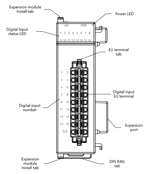
M16X Appearance
Technical Specifications
M16X Technical Specifications Table
|
Item |
Technical Specifications |
|
|
Model |
M16X |
|
|
Input Points |
16 |
|
|
Input Points Type |
24VDC Single-end input |
|
|
Maximum input frequency |
Medium-Low Speed,1kHz |
|
|
Input Signal Voltage |
24VDC±10% |
|
|
Input Current Threshold |
ON Current |
>4mA |
|
OFF Current |
<1.5mA |
|
|
Maximum Input Current |
7.6mA |
|
|
Input Resistance |
5.6kΩ |
|
|
Isolation Type |
Transformer/ Photocoupler Isolation,1500VAC/1 minute |
|
|
SINK /SOURCE Wiring |
Via variation of internal common terminal S/S and external common wiring |
|
|
Noise Filtering Time Constant |
DHF(0 ~ 70ms)+AHF(0.47ms) |
|
|
Operating Ambient Temperature |
0~55℃ |
|
|
Relative Humidity |
20 ~ 90% (non-condensing) |
|
|
Altitude |
≦2000m |
|
|
Vibration (Fixed by DIN RAIL) |
5~8.4Hz Amplitude: 3.5mm 8.4~150Hz Constant acceleration:19.6m/s^2(2G) 10G, 10 times each along the 3 axes (IEC61131-2 Standard) |
|
|
Shock |
10G, 3 times each along the 3 axes |
|
|
Noise Suppression |
1500Vp-p,Width 1us |
|
|
Withstand Voltage |
1500 VAC 1 minute (Between power terminals and input/output terminals, and between all external terminals and the housing) |
|
Status Indicator
M16X Status Indicator Table
|
Indicator |
instruction |
|
PWR Indicator |
Power ON: green light Power OFF: no light |
|
X1~X16 Input Indicator |
ON: green light OFF: no light |
Wiring
- Wiring of single-end common SINK input
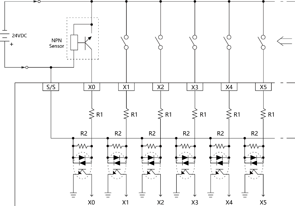
Wiring of single-end common SINK input
- Wiring of single-end common SOURCE input
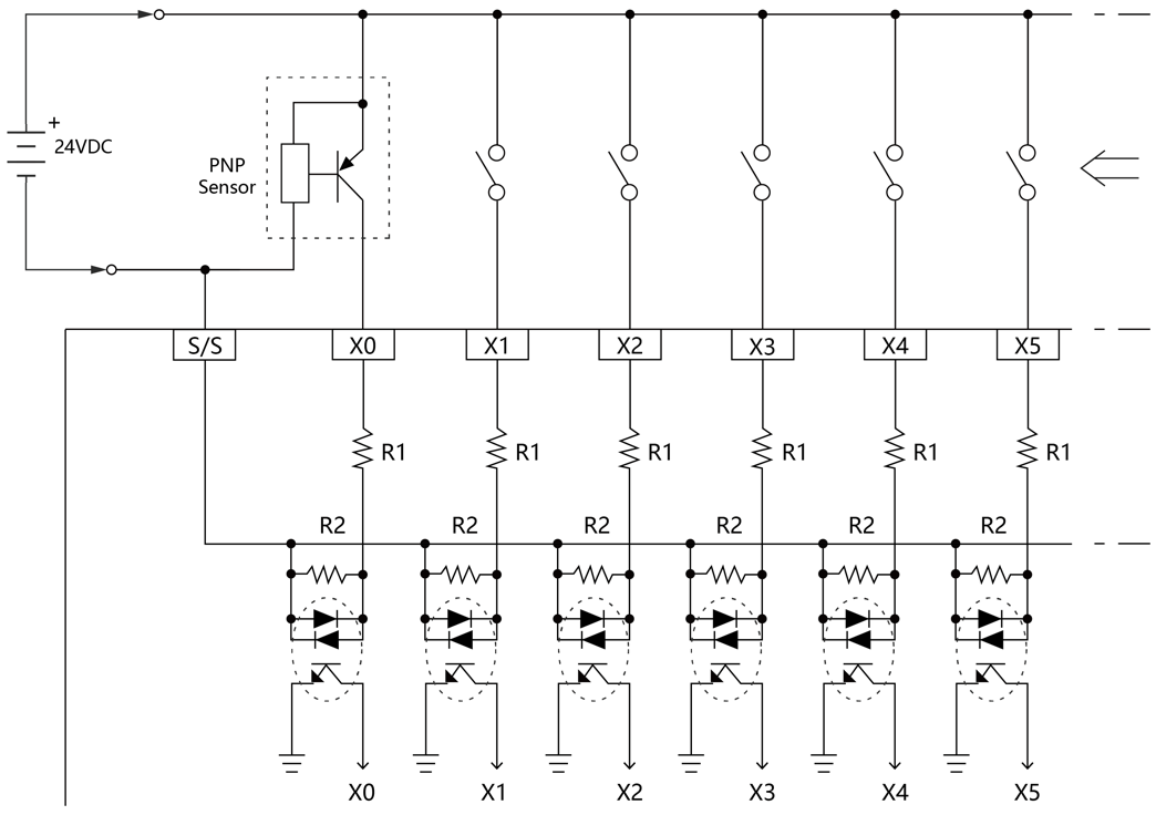
Wiring of single-end common SOURCE input
10-2 Digital Output Expansion Module Specifications
If the output point of the M Series CPU module is not enough for a specific application, then can expand it with the additional expansion modules.
10-2-1 M16YT / M16YJ Specifications
Appearance and Function
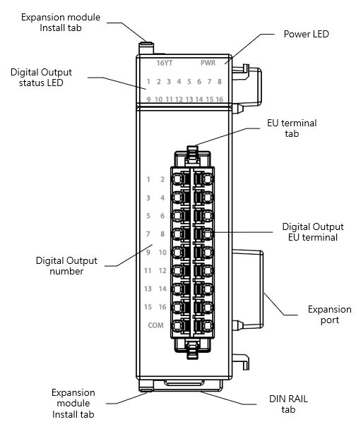
M16Y Appearance
Technical Specifications
M16YT / M16YJ Technical Specifications Table
|
Item |
Technical Specifications |
|
|
model |
M16YT / M16YJ |
|
|
Output Points |
16 |
|
|
Output Points Type |
Single-End Transistor Output; T-Transistor SINK(NPN) output ; J-Transistor SOURCE(PNP) output |
|
|
Maximum output frequency |
Medium speed,1kHz |
|
|
Working Voltage |
5~30VDC |
|
|
Maximum Load Current |
Resistive |
0.1A/Single 1.6A/COM |
|
Inductive |
||
|
Maximum Voltage Drop/conducing resistance |
2.2V |
|
|
Minimum Load |
– |
|
|
Leakage Current |
<0.1mA/30VDC |
|
|
Maximum Output Delay Time |
ON > OFF |
<10μS |
|
OFF > ON |
<40μS |
|
|
Over Current Protection |
N/A |
|
|
Isolation Type |
Photocoupler Isolation, 500VAC, 1 minute |
|
|
SINK /SOURCE Type |
Choose SINK/SOURCE by models and non-exchangeable |
|
|
Operating Ambient Temperature |
0~55℃ |
|
|
Relative Humidity |
20 ~ 90% (non-condensing) |
|
|
Altitude |
≦2000m |
|
|
Vibration (Fixed by DIN RAIL) |
5~8.4Hz Amplitude: 3.5mm 8.4~150Hz Constant acceleration:19.6m/s^2(2G) 10G, 10 times each along the 3 axes (IEC61131-2 Standard) |
|
|
Shock |
10G, 3 times each along the 3 axes |
|
|
Noise Suppression |
1500Vp-p,Width 1us |
|
|
Withstand Voltage |
1500 VAC 1 minute (Between power terminals and input/output terminals, and between all external terminals and the housing) |
|
Status Indicator
M16YT / M16YJ Status Indicator Table
|
Indicator |
instruction |
|
PWR LED |
Power ON: green light Power OFF: no light |
|
Y1~Y16 Output Indicator |
ON: green light OFF: no light |
Wiring
- Transistor Single-End SINK Output
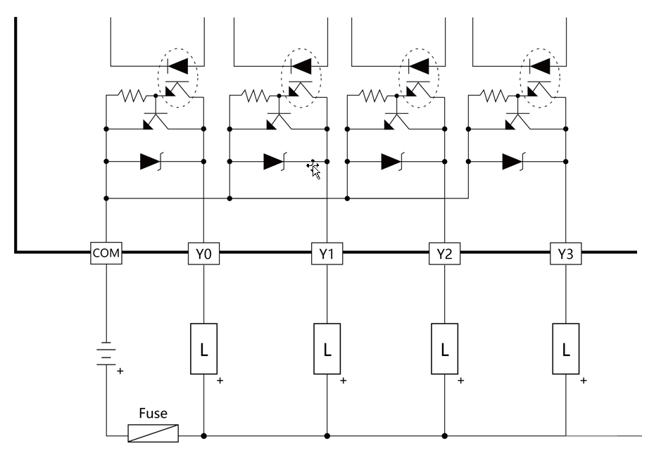
Transistor Single-End SINK Output
- Transistor Single-End SOURCE Output
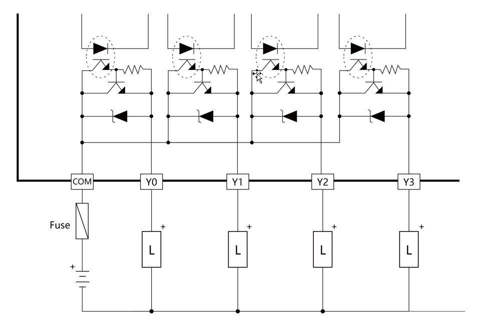
Transistor Single-End SOURCE Output
10-2-2 M16YR Specifications
Appearance and Function
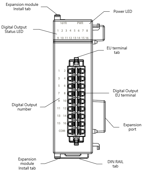
M M16R Appearance
Technical Specification
M16YR Technical Specification Table
|
Item |
Technical Specifications |
||
|
Model |
M16YR |
||
|
Output Points |
16 |
||
|
Output Points Type |
Single-End Relay Output |
||
|
Maximum output frequency |
For ON/OFF, not for frequently switching |
||
|
Working Voltage |
<250VAC,30VDC |
||
|
Maximum Load Current |
Resistive |
2A/single 8A/common |
|
|
Inductive |
80VA(AC)/24VA(DC) |
||
|
Maximum Voltage Drop/conducing resistance |
0.06V(Initial) |
||
|
Minimum Load |
2mA/DC Power |
||
|
Leakage Current |
– |
||
|
Maximum Output Delay Time |
ON > OFF |
10ms |
|
|
OFF > ON |
|||
|
Over Current Protection |
N/A |
||
|
Isolation Type |
Electromagnetic Isolation, 500VAC, |
||
|
SINK /SOURCE Type |
Bilateral device, can be arbitrarily set to SINK/SOURCE output |
||
|
Operating Ambient Temperature |
0~55℃ |
||
|
Relative Humidity |
20 ~ 90% (non-condensing) |
||
|
Altitude |
≦2000m |
||
|
Vibration (Fixed by DIN RAIL) |
5~8.4Hz Amplitude: 3.5mm 8.4~150Hz Constant acceleration:19.6m/s^2(2G) 10G, 10 times each along the 3 axes (IEC61131-2 Standard) |
||
|
Shock |
10G, 3 times each along the 3 axes |
||
|
Noise Suppression |
1500Vp-p,Width 1us |
||
|
Withstand Voltage |
1500 VAC 1 minute (Between power terminals and input/output terminals, and between all external terminals and the housing) |
||
Status Indicator
M16YR Status Indicator Table
|
Indicator |
instruction |
|
PWR Indicator |
Power ON: green light Power OFF: no light |
|
Y1~Y16 Output Indicator |
ON: green light OFF: no light |
Wiring
- Single-End Relay Output Circuit
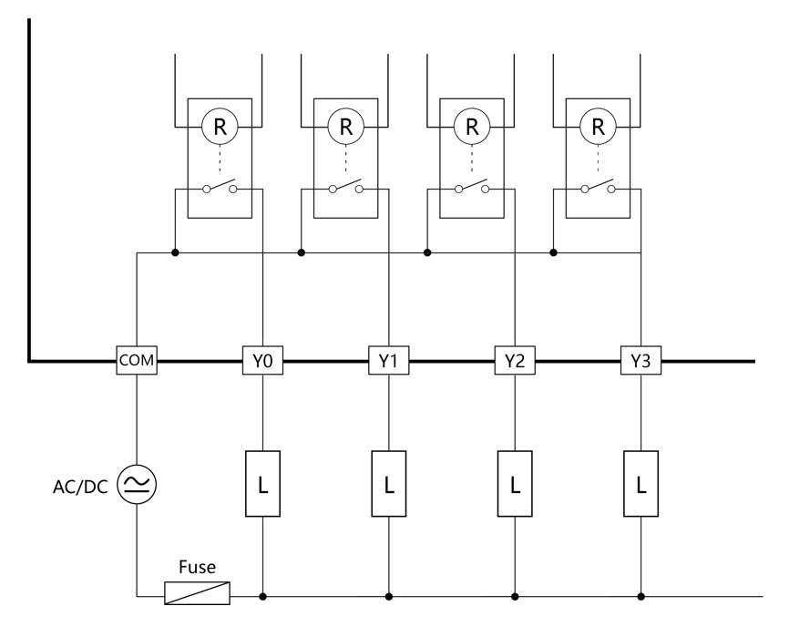
Single-End Relay Output Circuit
10-3 Digital Input /Output Combo Expansion Module Specifications
If the I/O point of the M Series CPU module is not enough for a specific application, then can expand it with the additional expansion modules.
10-3-1 M1616XYT/ M1616XYJ/ M1616XYR Specification
Appearance and Function
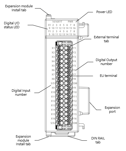
M1616XYT / M1616XYJ Appearance
Technical Specifications
M1616XYT/ M1616XYJ/ M1616XYR Input Technical Specifications Table
|
Item |
Technical Specifications |
|
|
Model |
M1616XYT/ M1616XYJ/ M1616XYR |
|
|
Input Points |
16 |
|
|
Input Points Type |
24VDC Single-end input |
|
|
Maximum input frequency |
Medium-Low Speed,1kHz |
|
|
Input Signal Voltage |
24VDC±10% |
|
|
Input Current Threshold |
ON Current |
>4mA |
|
OFF Current |
<1.5mA |
|
|
Maximum Input Current |
7.6mA |
|
|
Input Resistance |
5.6kΩ |
|
|
Isolation Type |
Transformer/ Photocoupler Isolation,500VAC/1 minute |
|
|
SINK /SOURCE Wiring |
Via variation of internal common terminal S/S and external common wiring |
|
|
Noise Filtering Time Constant |
DHF(0 ~ 70ms)+AHF(0.47ms) |
|
|
Operating Ambient Temperature |
0~55℃ |
|
|
Relative Humidity |
20 ~ 90% (non-condensing) |
|
|
Altitude |
≦2000m |
|
|
Vibration (Fixed by DIN RAIL) |
5~8.4Hz Amplitude: 3.5mm 8.4~150Hz Constant acceleration:19.6m/s^2(2G) 10G, 10 times each along the 3 axes (IEC61131-2 Standard) |
|
|
Shock |
10G, 3 times each along the 3 axes |
|
|
Noise Suppression |
1500Vp-p,Width 1us |
|
|
Withstand Voltage |
1500 VAC 1 minute (Between power terminals and input/output terminals, and between all external terminals and the housing) |
|
M1616XYT/ M1616XYJ/ M1616XYR Output Technical Specifications Table
|
Item |
Technical Specifications |
||
|
model |
M1616XYT/ M1616XYJ |
M1616XYR |
|
|
Output Points |
16 |
16 |
|
|
Output Points Type |
Single-End Transistor Output; T-Transistor SINK(NPN) output; J-Transistor SOURCE(PNP) output |
Single-End Relay Output |
|
|
Maximum output frequency |
Medium Speed,1kHz |
For ON/OFF, not for frequently switching |
|
|
Working Voltage |
5~30VDC |
<250VAC,30VDC |
|
|
Maximum Load Current |
Resistive |
0.1A |
2A/single, 8A/common |
|
Inductive |
80VA(AC)/24VA(DC) |
||
|
Maximum Voltage Drop/conducing resistance |
2.2V |
0.06V(Initial) |
|
|
Minimum Load |
– |
2mA/DC Power |
|
|
Leakage Current |
<0.1mA/30VDC |
– |
|
|
Maximum Output Delay Time |
ON > OFF |
<10μS |
10ms |
|
OFF > ON |
<40μS |
||
|
Over Current Protection |
N/A |
N/A |
|
|
Isolation Type |
Photocoupler Isolation, 500VAC, 1 minute |
Electromagnetic Isolation, 500VAC, 1 minute |
|
|
SINK /SOURCE Type |
Choose SINK/SOURCE by models and non-exchangeable |
Bilateral device, can be arbitrarily set to SINK/SOURCE output |
|
|
Operating Ambient Temperature |
0~55℃ |
||
|
Relative Humidity |
20 ~ 90% (non-condensing) |
||
|
Altitude |
≦2000m |
||
|
Vibration (Fixed by DIN RAIL) |
5~8.4Hz Amplitude: 3.5mm 8.4~150Hz Constant acceleration:19.6m/s^2(2G) 10G, 10 times each along the 3 axes (IEC61131-2 Standard) |
||
|
Shock |
10G, 3 times each along the 3 axes |
||
|
Noise Suppression |
1500Vp-p,Width 1us |
||
|
Withstand Voltage |
1500 VAC 1 minute (Between power terminals and input/output terminals, and between all external terminals and the housing) |
||
Status Indicator
M16X Status Indicator Table
|
Indicator |
instruction |
|
PWR Indicator |
Power ON: green light Power OFF: no light |
|
X1~X16 Input Indicator |
ON: green light OFF: no light |
|
Y1~Y16 output Indicator |
ON: green light OFF: no light |
Wiring
- Wiring of single-end common SINK input
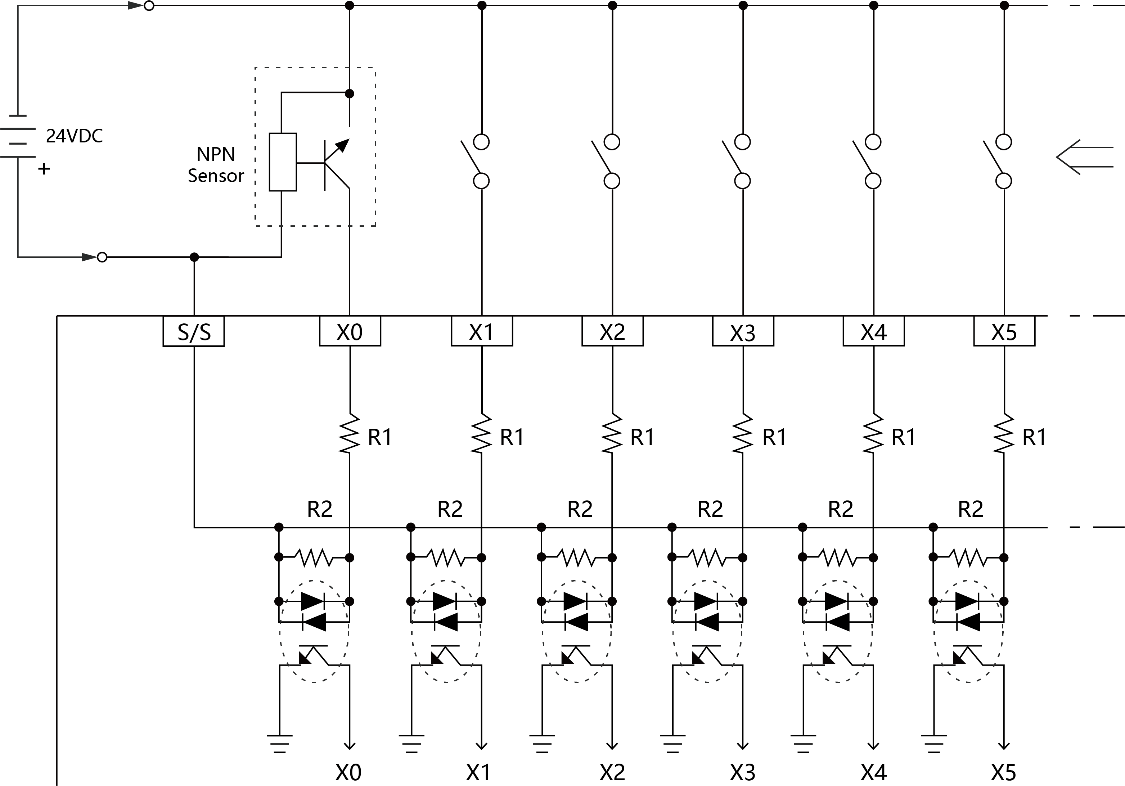
Wiring of single-end common SINK input
- Wiring of single-end common SOURCE input
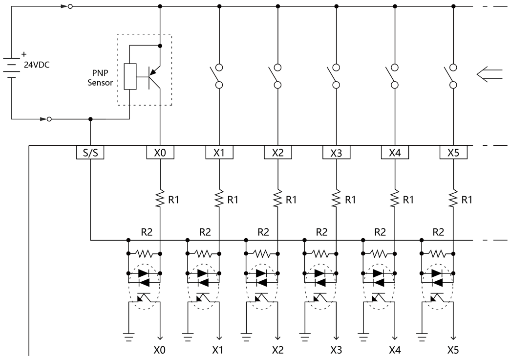
Wiring of single-end common SOURCE input
- Transistor Single-End SINK Output
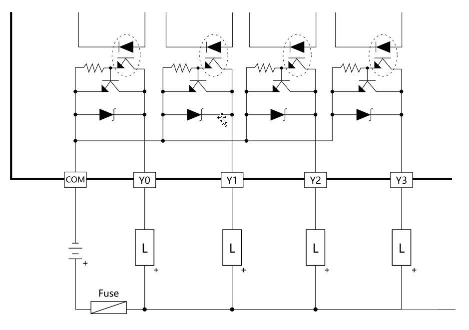
Transistor Single-End SINK Output
- Transistor Single-End SOURCE Output
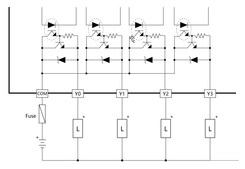
Transistor Single-End SOURCE Output
10-4 Analog Input Expansion Module Specifications
If the Analog input point of the M Series CPU module is not enough for a specific application, then can expand it with the additional expansion modules.
10-4-1 M04AD Specification
Appearance and Function
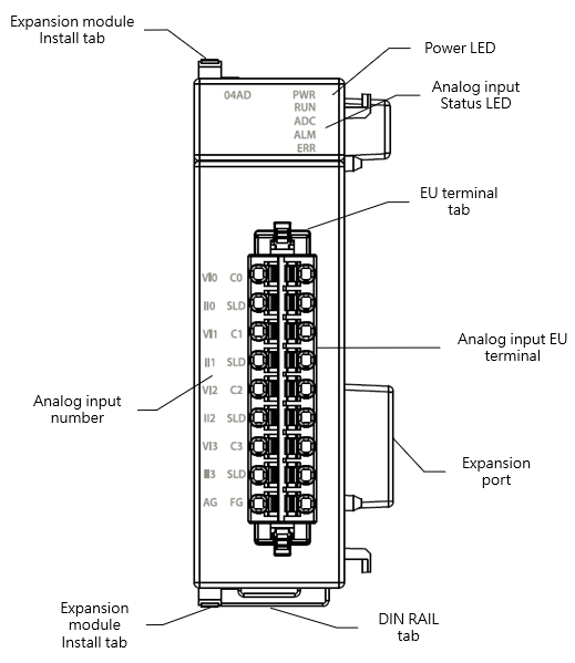
M04AD Appearance
Technical Specification
M04AD Technical Specification Table
|
Item |
Technical Specification |
|||
|
Model |
M04AD |
|||
|
Input Point |
4 |
|||
|
Conversion speed |
High Speed: 300us/Ch Medium Speed: 500us/Ch Low Speed: 1ms/Ch 50Hz filter: 80ms/Ch 60Hz filter: 68ms/Ch |
|||
|
Analog Input Characteristics and Resolution |
Analog input range |
Data |
Resolution |
|
|
Voltage |
-10~+10V |
-8192~8191 |
1.22mV |
|
|
-5~+5V |
-8192~8191 |
0.61mV |
||
|
0~10V |
0~16383 |
0.61mV |
||
|
0~5V |
0~16383 |
0.305mV |
||
|
1~5V |
0~16383 |
0.244mV |
||
|
Current |
-20mA~+20mA |
-8192~8191 |
2.44uA |
|
|
0~20mA |
0~16383 |
1.22uA |
||
|
4~20mA |
0~16383 |
0.976uA |
||
|
Conversion precision |
Voltage |
±0.1% (25°C±5℃) ±0.2% (0~55℃) |
||
|
Current |
±0.2% (25°C±5℃) ±0.4% (0~55℃) |
|||
|
AD Converter |
24-Bit |
|||
|
Input Resistance |
Voltage:1MΩ Current:250Ω |
|||
|
Hardware maximum input |
Voltage:-15V~+15V Current:-30mA~+30mA |
|||
|
Insulation |
Between analog input and CPU:insulated(Digital isolators, transformers) Between analog input channels:non-insulated |
|||
|
Operating Ambient Temperature |
0~55℃ |
|||
|
Relative Humidity |
20 ~ 90% (non-condensing) |
|||
|
Altitude |
≦2000m |
|||
|
Vibration (Fixed by DIN RAIL) |
5~8.4Hz Amplitude: 3.5mm 8.4~150Hz Constant acceleration:19.6m/s^2(2G) 10G, 10 times each along the 3 axes (IEC61131-2 Standard) |
|||
|
Shock |
10G, 3 times each along the 3 axes |
|||
|
Noise Suppression |
1500Vp-p,Width 1us |
|||
|
Withstand Voltage |
1500 VAC 1 minute (Between power terminals and input/output terminals, and between all external terminals and the housing) |
|||
Status Indicator
M04AD Status Indicator Table
|
Indicator |
instruction |
|
PWR Indicator |
Power ON: green light Power OFF: no light |
|
RUN Indicator |
Running: green light |
|
ADC Indicator |
ADC Converting: yellow light |
|
ALM Indicator |
On Alert: red light |
|
ERR Indicator |
In ERROR: red light |
Wiring
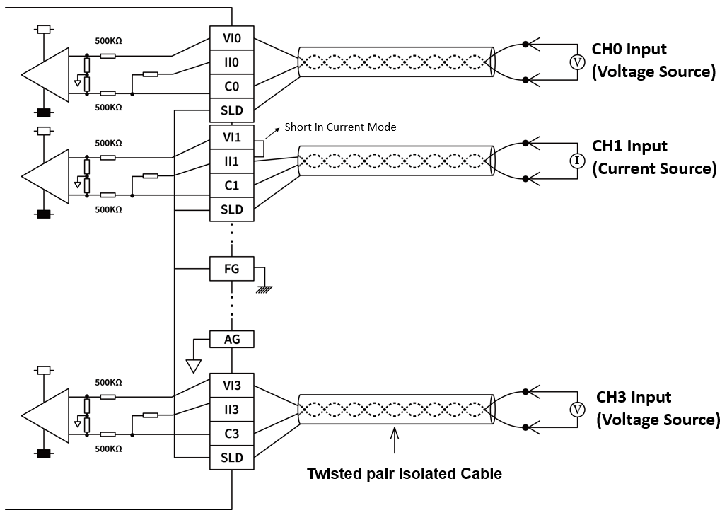
M04AD Wiring
10-4-2 M04ADS Specification
Appearance and Function
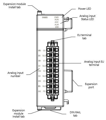
M04ADS Appearance
Technical Specification
M04ADS Technical Specification Table
|
Item |
Technical Specification |
|||
|
Model |
M04ADS |
|||
|
Input Point |
4 |
|||
|
Conversion speed |
Medium Speed: 500us/Ch Low Speed: 1ms/Ch 50Hz filter: 80ms/Ch 60Hz filter: 68ms/Ch |
|||
|
Analog Input Characteristics and Resolution |
Analog input range |
Data |
Resolution |
|
|
Voltage |
-10~+10V |
-32768~32767 |
0.3mV |
|
|
-5~+5V |
-32768~32767 |
0.15mV |
||
|
0~10V |
0~65535 |
0.15mV |
||
|
0~5V |
0~65535 |
0.075mV |
||
|
1~5V |
0~65535 |
0.06mV |
||
|
Current |
-20mA~+20mA |
-32768~32767 |
0.6uA |
|
|
0~20mA |
0~65535 |
0.3uA |
||
|
4~20mA |
0~65535 |
0.24uA |
||
|
Conversion precision |
Voltage |
±0.1% (25°C±5℃) ±0.2% (0~55℃) |
||
|
Current |
±0.2% (25°C±5℃) ±0.4% (0~55℃) |
|||
|
AD Converter |
24-Bit |
|||
|
Input Resistance |
Voltage:1MΩ Current:250Ω |
|||
|
Hardware maximum input |
Voltage:-15V~+15V Current:-30mA~+30mA |
|||
|
Insulation |
Between analog input and CPU:insulated(Digital isolators, transformers) Between analog input channels:non-insulated |
|||
|
Operating Ambient Temperature |
0~55℃ |
|||
|
Relative Humidity |
20 ~ 90% (non-condensing) |
|||
|
Altitude |
≦2000m |
|||
|
Vibration (Fixed by DIN RAIL) |
5~8.4Hz Amplitude: 3.5mm 8.4~150Hz Constant acceleration:19.6m/s^2(2G) 10G, 10 times each along the 3 axes (IEC61131-2 Standard) |
|||
|
Shock |
10G, 3 times each along the 3 axes |
|||
|
Noise Suppression |
1500Vp-p,Width 1us |
|||
|
Withstand Voltage |
1500 VAC 1 minute (Between power terminals and input/output terminals, and between all external terminals and the housing) |
|||
Status Indicator
M04ADS Status Indicator Table
|
Indicator |
instruction |
|
PWR Indicator |
Power ON: green light Power OFF: no light |
|
RUN Indicator |
Running: green light |
|
ADC Indicator |
ADC Converting: yellow light |
|
ALM Indicator |
On Alert: red light |
|
ERR Indicator |
In ERROR: red light |
Wiring
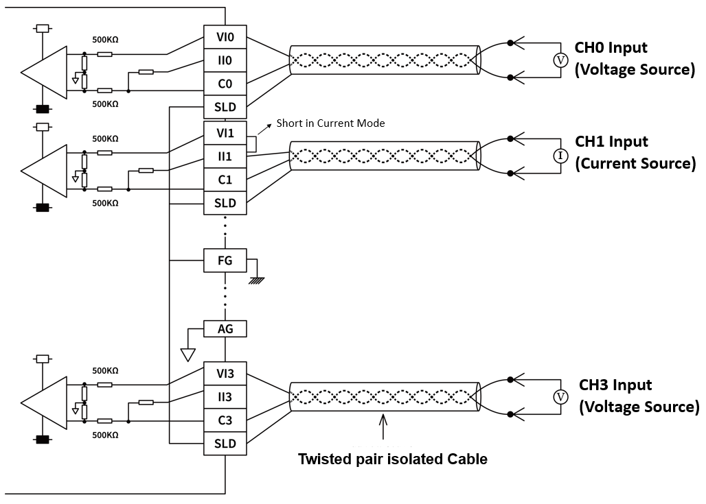
M04ADS Wiring
10-4-3 M08ADS Specification
Appearance and Function
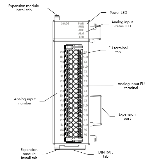
M08ADS Appearance
Technical Specification
M08ADS Technical Specification Table
|
Item |
Technical Specification |
|||
|
Model |
M08ADS |
|||
|
Input Point |
8 |
|||
|
Conversion speed |
Medium Speed: 500us/Ch Low Speed: 1ms/Ch 50Hz filter: 80ms/Ch 60Hz filter: 68ms/Ch |
|||
|
Analog Input Characteristics and Resolution |
Analog input range |
Data |
Resolution |
|
|
Voltage |
-10~+10V |
-32768~32767 |
0.3mV |
|
|
-5~+5V |
-32768~32767 |
0.15mV |
||
|
0~10V |
0~65535 |
0.15mV |
||
|
0~5V |
0~65535 |
0.075mV |
||
|
1~5V |
0~65535 |
0.06mV |
||
|
Current |
-20mA~+20mA |
-32768~32767 |
0.6uA |
|
|
0~20mA |
0~65535 |
0.3uA |
||
|
4~20mA |
0~65535 |
0.24uA |
||
|
Conversion precision |
Voltage |
±0.1% (25°C±5℃) ±0.2% (0~55℃) |
||
|
Current |
±0.2% (25°C±5℃) ±0.4% (0~55℃) |
|||
|
AD Converter |
24-Bit |
|||
|
Input Resistance |
Voltage:1MΩ Current:250Ω |
|||
|
Hardware maximum input |
Voltage:-15V~+15V Current:-30mA~+30mA |
|||
|
Insulation |
Between analog input and CPU:insulated(Digital isolators, transformers) Between analog input channels:non-insulated |
|||
|
Operating Ambient Temperature |
0~55℃ |
|||
|
Relative Humidity |
20 ~ 90% (non-condensing) |
|||
|
Altitude |
≦2000m |
|||
|
Vibration (Fixed by DIN RAIL) |
5~8.4Hz Amplitude: 3.5mm 8.4~150Hz Constant acceleration:19.6m/s^2(2G) 10G, 10 times each along the 3 axes (IEC61131-2 Standard) |
|||
|
Shock |
10G, 3 times each along the 3 axes |
|||
|
Noise Suppression |
1500Vp-p,Width 1us |
|||
|
Withstand Voltage |
1500 VAC 1 minute (Between power terminals and input/output terminals, and between all external terminals and the housing) |
|||
Status Indicator
M04ADS Status Indicator Table
|
Indicator |
instruction |
|
PWR Indicator |
Power ON: green light Power OFF: no light |
|
RUN Indicator |
Running: green light |
|
ADC Indicator |
ADC Converting: yellow light |
|
ALM Indicator |
On Alert: red light |
|
ERR Indicator |
In ERROR: red light |
Wiring
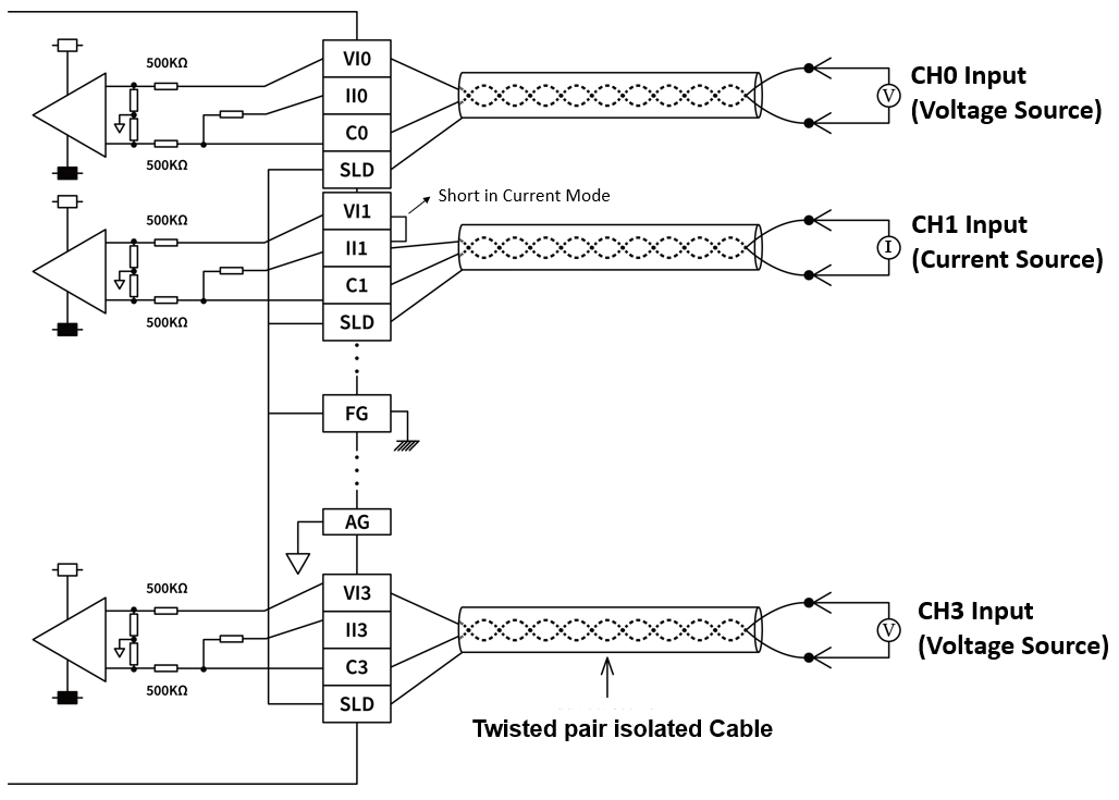
M08ADS Wiring
10-4-4 M04ADR Specification
Appearance and Function
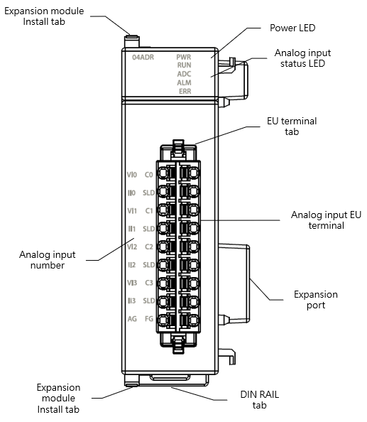
M04ADR Appearance
Technical Specification
M04ADR Technical Specification
|
Item |
Technical Specification |
|||
|
Model |
M04ADR |
|||
|
Input Points |
4 |
|||
|
Conversion speed |
High Speed: 1.5ms/Ch. Medium Speed: 4ms/Ch. Low Speed: 15ms/Ch. 50Hz Filter: 80ms/Ch. 60Hz Filter: 68ms/Ch. |
|||
|
Analog Input Characteristics and Resolution |
Analog input range |
Data |
Resolution |
|
|
Voltage |
-10~+10V |
-80000~80000 |
0.125mV |
|
|
-5~+5V |
-80000~80000 |
0.0625mV |
||
|
0~10V |
0~80000 |
0.125mV |
||
|
0~5V |
0~80000 |
0.0625mV |
||
|
1~5V |
0~80000 |
0.05mV |
||
|
Current |
-20mA~+20mA |
-80000~80000 |
0.25uA |
|
|
0~20mA |
0~80000 |
0.25uA |
||
|
4~20mA |
0~80000 |
0.2uA |
||
|
Conversion precision |
Voltage |
±0.1% (25°C±5℃) ±0.2% (0~55℃) |
||
|
Current |
±0.1% (25°C±5℃) ±0.2% (0~55℃) |
|||
|
AD Converter |
24-Bit |
|||
|
Input Resistance |
Voltage:1MΩ Current:250Ω |
|||
|
Hardware maximum input |
Voltage:-15V~+15V Current:-30mA~+30mA |
|||
|
Insulation |
Between analog input and CPU:insulated(Digital isolators, transformers) Between analog input channels:non-insulated |
|||
|
Operating Ambient Temperature |
0~55℃ |
|||
|
Relative Humidity |
20 ~ 90% (non-condensing) |
|||
|
Altitude |
≦2000m |
|||
|
Vibration (Fixed by DIN RAIL) |
5~8.4Hz Amplitude: 3.5mm 8.4~150Hz Constant acceleration:19.6m/s^2(2G) 10G, 10 times each along the 3 axes (IEC61131-2 Standard) |
|||
|
Shock |
10G, 3 times each along the 3 axes |
|||
|
Noise Suppression |
1500Vp-p,Width 1us |
|||
|
Withstand Voltage |
1500 VAC 1 minute (Between power terminals and input/output terminals, and between all external terminals and the housing) |
|||
Status Indicator
M04ADR Status Indicator Table
|
Indicator |
instruction |
|
PWR Indicator |
Power ON: green light Power OFF: no light |
|
RUN Indicator |
Running: green light |
|
ADC Indicator |
ADC Converting: yellow light |
|
ALM Indicator |
On Alert: red light |
|
ERR Indicator |
In ERROR: red light |
Wiring
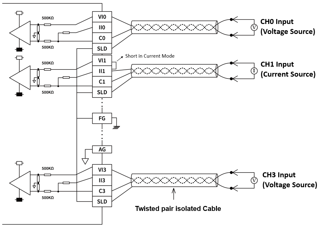
M04ADR Wiring
10-5 Analog Output Expansion Module Specifications
If the Analog output point of the M Series CPU module is not enough for a specific application, then can expand it with the additional expansion modules.
10-5-1 M04DA Specification
Appearance and Function
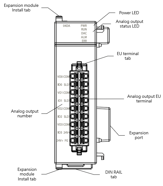
M04DA Appearance
Technical Specification
M04DA Technical Specification
|
Item |
Technical Specification |
|||
|
model |
M04DA |
|||
|
Output Point |
4 |
|||
|
Conversion speed |
1ms/channel |
|||
|
Analog output characteristics and resolution |
Analog output range |
Data |
Resolution |
|
|
Voltage |
-10~+10V |
-8192~8191 |
1.22mV |
|
|
-5~+5V |
-8192~8191 |
0.61mV |
||
|
0~10V |
0~16383 |
0.61mV |
||
|
0~5V |
0~16383 |
0.305mV |
||
|
1~5V |
0~16383 |
0.244mV |
||
|
Current |
0~20mA |
0~16383 |
1.22μA |
|
|
4~20mA |
0~16383 |
0.976μA |
||
|
Conversion precision |
Voltage |
±0.2% (25℃±5℃) ±0.5% (0~55℃) |
||
|
Current |
±0.2% (25℃±5℃) ±0.5% (0~55℃) |
|||
|
DA Converter |
16-Bit |
|||
|
Minimum load impedance |
Voltage:1kΩ |
|||
|
Maximum load impedance |
Current:500Ω |
|||
|
Hardware maximum output |
Voltage |
-10.2~+10.2V -5.1~+5.1V -0.2~10.2V -0.1~5.1V 0.9~5.1V |
||
|
Current |
0~20.2mA 4~20.2mA |
|||
|
Insulation |
Between analog output and CPU:insulated(Digital isolators, transformers) Between analog output channels:non-insulated |
|||
|
Operating Ambient Temperature |
0~55℃ |
|||
|
Relative Humidity |
20 ~ 90% (non-condensing) |
|||
|
Altitude |
≦2000m |
|||
|
Vibration (Fixed by DIN RAIL) |
5~8.4Hz Amplitude: 3.5mm 8.4~150Hz Constant acceleration:19.6m/s^2(2G) 10G, 10 times each along the 3 axes (IEC61131-2 Standard) |
|||
|
Shock |
10G, 3 times each along the 3 axes |
|||
|
Noise Suppression |
1500Vp-p,Width 1us |
|||
|
Withstand Voltage |
1500 VAC 1 minute (Between power terminals and input/output terminals, and between all external terminals and the housing) |
|||
Status Indicator
M04DA Status Indicator Table
|
Indicator |
instruction |
|
PWR Indicator |
Power ON: green light Power OFF: no light |
|
RUN Indicator |
Running: green light |
|
DAC Indicator |
DAC Converting: yellow light |
|
ALM Indicator |
On Alert: red light |
|
ERR Indicator |
In ERROR: red light |
Wiring
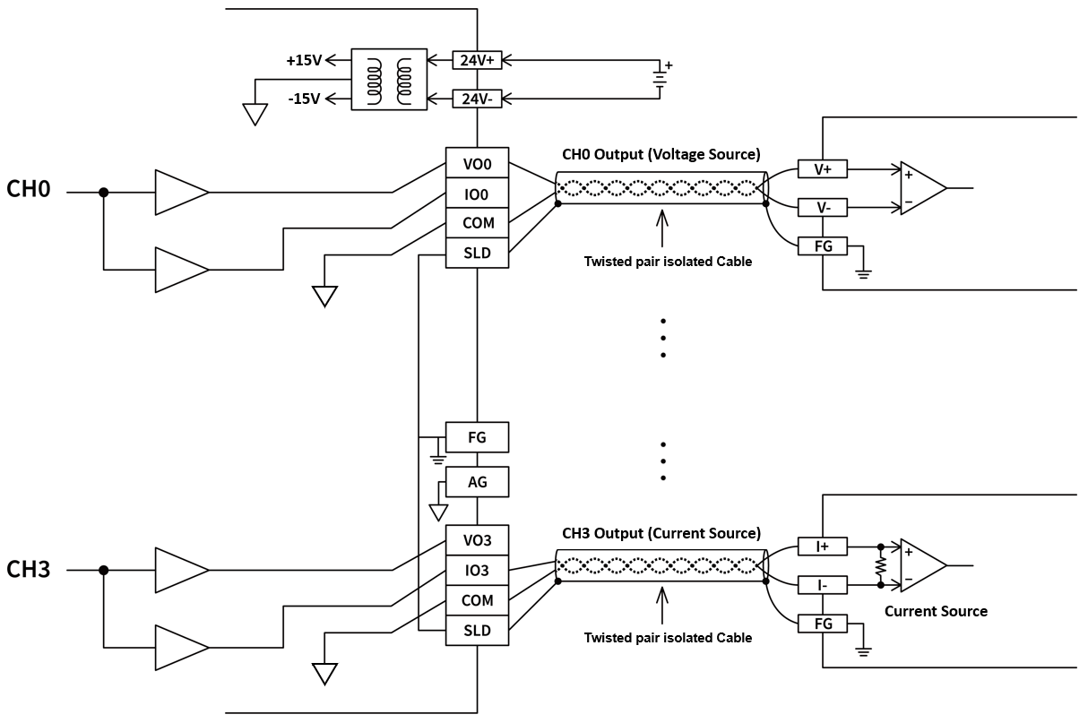
M04DA Wiring
10-5-2 M04DAR Specification
Appearance and Function
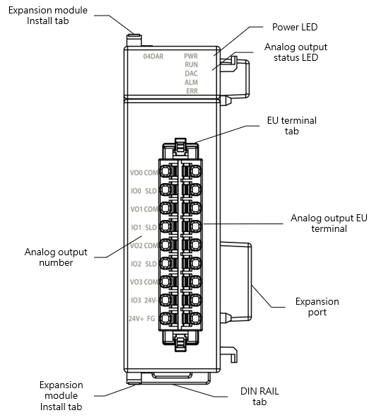
M04DAR Appearance
Technical Specification
M04DAR Technical Specification
|
Item |
Technical Specification |
|||
|
model |
M04DAR |
|||
|
Output Point |
4 |
|||
|
Conversion speed |
0.5ms/channel |
|||
|
Analog output characteristics and resolution |
Analog output range |
Data |
Resolution |
|
|
Voltage |
-10~+10V |
-27000~27000 |
0.37mV |
|
|
-5~+5V |
-27000~27000 |
0.185mV |
||
|
0~10V |
0~27000 |
0.37mV |
||
|
0~5V |
0~27000 |
0.185mV |
||
|
1~5V |
0~27000 |
0.48mV |
||
|
Current |
0~20mA |
0~27000 |
0.74μA |
|
|
4~20mA |
0~27000 |
0.592μA |
||
|
Conversion precision |
Voltage |
±0.05% (25℃±5℃) ±0.3% (0~55℃) |
||
|
Current |
±0.05% (25℃±5℃) ±0.3% (0~55℃) |
|||
|
DA Converter |
16-Bit |
|||
|
Minimum load impedance |
Voltage:1kΩ |
|||
|
Maximum load impedance |
Current:500Ω |
|||
|
hardware output |
Voltage |
-10.2~+10.2V -5.1~+5.1V -0.2~10.2V -0.1~5.1V 0.9~5.1V |
||
|
Current |
0~20.2mA 4~20.2mA |
|||
|
Insulation |
Between analog output and CPU:insulated(Digital isolators, transformers) Between analog output channels:non-insulated |
|||
|
Operating Ambient Temperature |
0~55℃ |
|||
|
Relative Humidity |
20 ~ 90% (non-condensing) |
|||
|
Altitude |
≦2000m |
|||
|
Vibration (Fixed by DIN RAIL) |
5~8.4Hz Amplitude: 3.5mm 8.4~150Hz Constant acceleration:19.6m/s^2(2G) 10G, 10 times each along the 3 axes (IEC61131-2 Standard) |
|||
|
Shock |
10G, 3 times each along the 3 axes |
|||
|
Noise Suppression |
1500Vp-p,Width 1us |
|||
|
Withstand Voltage |
1500 VAC 1 minute (Between power terminals and input/output terminals, and between all external terminals and the housing) |
|||
Status Indicator
M04DAR Status Indicator Table
|
Indicator |
instruction |
|
PWR Indicator |
Power ON: green light Power OFF: no light |
|
RUN Indicator |
Running: green light |
|
DAC Indicator |
DAC Converting: yellow light |
|
ALM Indicator |
On Alert: red light |
|
ERR Indicator |
In ERROR: red light |
Wiring
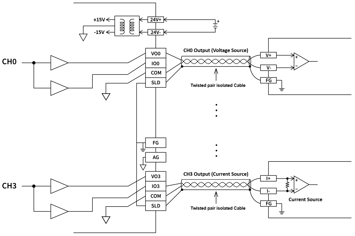
M04DAR Wiring
10-6 Analog Input/Output Combo Expansion Module Specifications
If the Analog input/output point of the M Series CPU module is not enough for a specific application, then can expand it with the additional expansion modules.
10-6-1 M0202AH Specifications
Appearance and Function
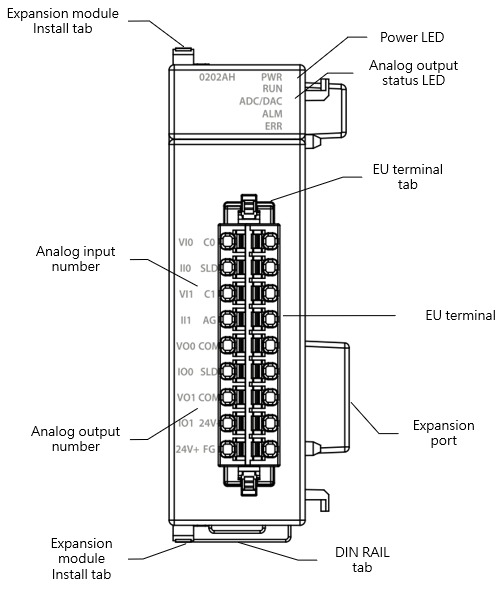
M0202AH Appearance
Technical Specification
M0202AH Technical Specification
|
Item |
Technical Specification |
|||||
|
Model |
M0202AH |
|||||
|
Input Specifications |
||||||
|
Input Point |
2 |
|||||
|
Conversion speed |
High Speed: 300us/Ch Medium Speed: 500us/Ch Low Speed: 1ms/Ch 50Hz filter: 80ms/Ch 60Hz filter: 68ms/Ch |
|||||
|
Analog Input Characteristics and Resolution |
Analog input range |
Data |
Resolution |
|||
|
Voltage |
-10~+10V |
-8192~8191 |
1.22mV |
|||
|
-5~+5V |
-8192~8191 |
0.61mV |
||||
|
0~10V |
0~16383 |
0.61mV |
||||
|
0~5V |
0~16383 |
0.305mV |
||||
|
1~5V |
0~16383 |
0.244mV |
||||
|
Current |
-20mA~+20mA |
-8192~8191 |
2.44uA |
|||
|
0~20mA |
0~16383 |
1.22uA |
||||
|
4~20mA |
0~16383 |
0.976uA |
||||
|
Conversion precision |
Voltage |
±0.1% (25°C±5℃) ±0.2% (0~55℃) |
||||
|
Current |
±0.2% (25°C±5℃) ±0.4% (0~55℃) |
|||||
|
AD Converter |
24-Bit |
|||||
|
Input Resistance |
Voltage:1MΩ Current:250Ω |
|||||
|
Hardware maximum input |
Voltage:-15V~+15V Current:-30mA~+30mA |
|||||
|
Output Specifications |
||||||
|
Output Point |
2 |
|||||
|
Conversion speed |
1ms/channel |
|||||
|
Analog output characteristics and resolution |
Analog output range |
Data |
Resolution |
|||
|
Voltage |
-10~+10V |
-8192~8191 |
1.22mV |
|||
|
-5~+5V |
-8192~8191 |
0.61mV |
||||
|
0~10V |
0~16383 |
0.61mV |
||||
|
0~5V |
0~16383 |
0.305mV |
||||
|
1~5V |
0~16383 |
0.244mV |
||||
|
Current |
0~20mA |
0~16383 |
1.22μA |
|||
|
4~20mA |
0~16383 |
0.976μA |
||||
|
Conversion precision |
Voltage |
±0.2% (25℃±5℃) ±0.5% (0~55℃) |
||||
|
Current |
±0.2% (25℃±5℃) ±0.5% (0~55℃) |
|||||
|
DA Converter |
24-Bit |
|||||
|
Minimum load impedance |
Voltage:1kΩ |
|||||
|
Maximum load impedance |
Current:500Ω |
|||||
|
Hardware Maximum output |
Voltage |
-10.2~+10.2V -5.1~+5.1V -0.2~10.2V -0.1~5.1V 0.9~5.1V |
||||
|
Current |
0~20.2mA 4~20.2mA |
|||||
|
Common Specifications |
||||||
|
Insulation |
Between analog input/output and CPU:insulated(Digital isolators, transformers) Between analog input/output channels:non-insulated |
|||||
|
Operating Ambient Temperature |
0~55℃ |
|||||
|
Relative Humidity |
20 ~ 90% (non-condensing) |
|||||
|
Altitude |
≦2000m |
|||||
|
Vibration (Fixed by DIN RAIL) |
5~8.4Hz Amplitude: 3.5mm 8.4~150Hz Constant acceleration:19.6m/s^2(2G) 10G, 10 times each along the 3 axes (IEC61131-2 Standard) |
|||||
|
Shock |
10G, 3 times each along the 3 axes |
|||||
|
Noise Suppression |
1500Vp-p,Width 1us |
|||||
|
Withstand Voltage |
1500 VAC 1 minute (Between power terminals and input/output terminals, and between all external terminals and the housing) |
|||||
Status Indicator
M0202AH Status Indicator Table
|
Indicator |
instruction |
|
PWR Indicator |
Power ON: green light Power OFF: no light |
|
RUN Indicator |
Running: green light |
|
ADC/DAC Indicator |
ADC/DAC Converting: yellow light |
|
ALM Indicator |
On Alert: red light |
|
ERR Indicator |
In ERROR: red light |
Wiring
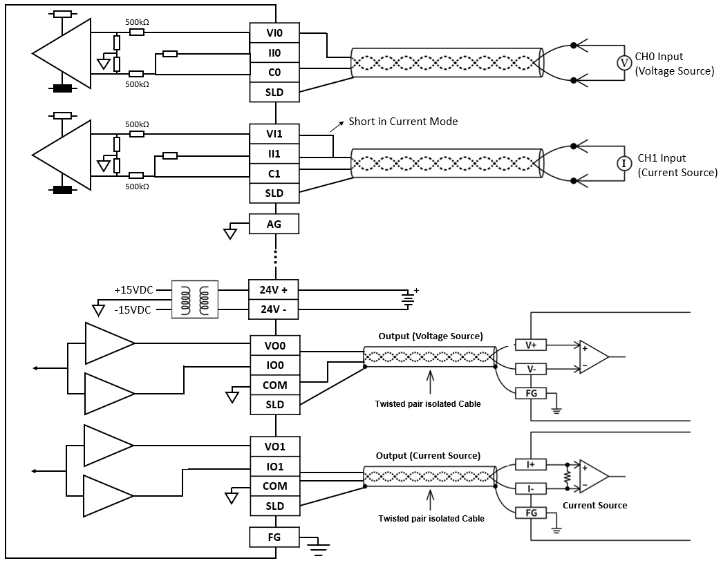
M0202AH Wiring
10-7 Temperature Expansion Module Specifications
If the temperature input point of the M Series CPU module is not enough for a specific application, then can expand it with the additional expansion modules.
10-7-1 M04TC Specification
Appearance and Function
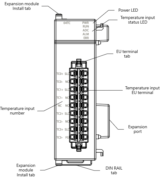
M04TC Appearance
Technical Specification
M04TC Technical Specifications Table
|
Item |
Technical Specification |
|
Model |
M04TC |
|
Input Points |
4 |
|
Resolution |
0.1℃ |
|
Sampling cycle |
High Speed:200ms/ch Standard:400ms/ch |
|
Temperature sensor type |
K, J, E, T, R, B, N, S, mV |
|
Conversion precision |
±0.5% (25°C±5℃) ±1% (0~55℃) |
|
AD Converter |
24-Bit |
|
Operating mode |
PID Control ON/OFF Control |
|
Control cycle |
0.1~30 Second+ 1 Scan time |
|
Tuning |
PID Auto Tuning |
|
Insulation |
Between analog input and CPU:insulated(Digital isolators) Between analog input channels:insulated(optocoupler isolator) |
|
Operating Ambient Temperature |
0~55℃ |
|
Relative Humidity |
20 ~ 90% (non-condensing) |
|
Altitude |
≦2000m |
|
Vibration (Fixed by DIN RAIL) |
5~8.4Hz Amplitude: 3.5mm 8.4~150Hz Constant acceleration:19.6m/s^2(2G) 10G, 10 times each along the 3 axes (IEC61131-2 Standard) |
|
Shock |
10G, 3 times each along the 3 axes |
|
Noise Suppression |
1500Vp-p,Width 1us |
|
Withstand Voltage |
1500 VAC 1 minute (Between power terminals and input/output terminals, and between all external terminals and the housing) |
Status Indicator
M04TC Status Indicator Table
|
Indicator |
instruction |
|
PWR Indicator |
Power ON: green light Power OFF: no light |
|
RUN Indicator |
Running: green light |
|
ADC Indicator |
ADC Converting: yellow light |
|
ALM Indicator |
On Alert: red light |
|
ERR Indicator |
In ERROR: red light |
Wiring
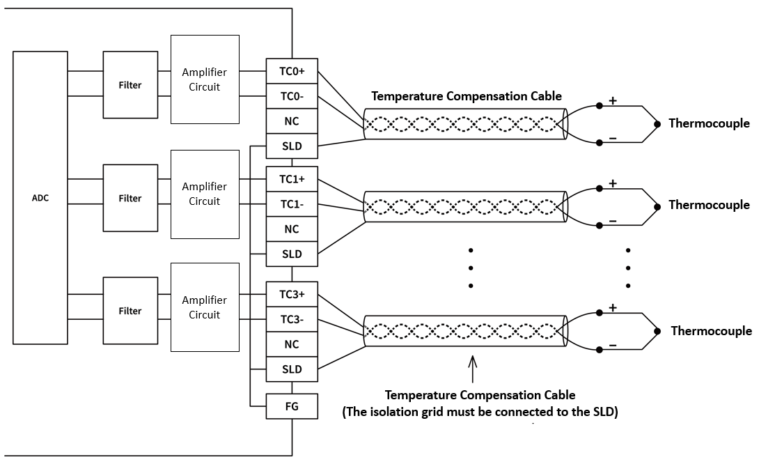
M04TC Wiring
10-7-2 M04TCR Specification
Appearance and Function
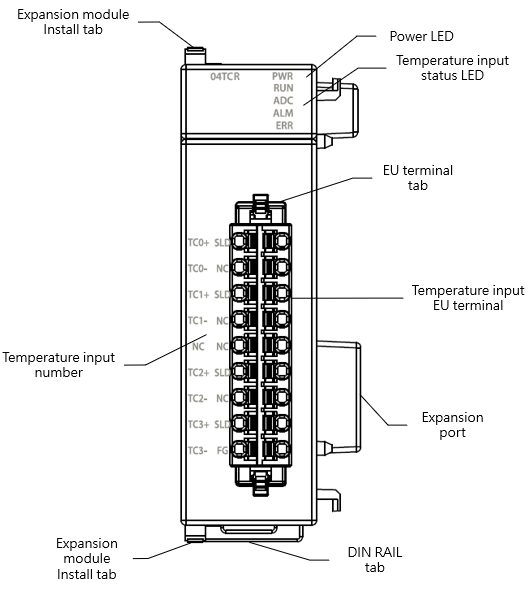
M04TCR Appearance
Technical Specification
M04TCR Technical Specifications Table
|
Item |
Technical Specification |
|
Model |
M04TCR |
|
Input Points |
4 |
|
Resolution |
0.1℃ |
|
Sampling cycle |
High Speed:100ms/ch Standard:200ms/ch |
|
Temperature sensor type |
K, J, E, T, R, B, N, S, mV |
|
Conversion precision |
±0.2% (25°C±5℃) ±0.4% (0~55℃) |
|
AD Converter |
24-Bit |
|
Operating mode |
PID Control ON/OFF Control |
|
Control cycle |
0.1~30 Second+ 1 Scan time |
|
Tuning |
PID Auto Tuning |
|
Insulation |
Between analog input and CPU:insulated(Digital isolators) Between analog input channels:insulated(optocoupler isolator) |
|
Operating Ambient Temperature |
0~55℃ |
|
Relative Humidity |
20 ~ 90% (non-condensing) |
|
Altitude |
≦2000m |
|
Vibration (Fixed by DIN RAIL) |
5~8.4Hz Amplitude: 3.5mm 8.4~150Hz Constant acceleration:19.6m/s^2(2G) 10G, 10 times each along the 3 axes (IEC61131-2 Standard) |
|
Shock |
10G, 3 times each along the 3 axes |
|
Noise Suppression |
1500Vp-p,Width 1us |
|
Withstand Voltage |
1500 VAC 1 minute (Between power terminals and input/output terminals, and between all external terminals and the housing) |
Status Indicator
M04TCR Status Indicator Table
|
Indicator |
instruction |
|
PWR Indicator |
Power ON: green light Power OFF: no light |
|
RUN Indicator |
Running: green light |
|
ADC Indicator |
ADC Converting: yellow light |
|
ALM Indicator |
On Alert: red light |
|
ERR Indicator |
In ERROR: red light |
Wiring
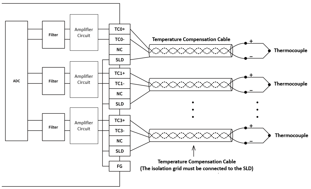
M04TCR Wiring
10-7-3 M04RTD Specification
Appearance and Function
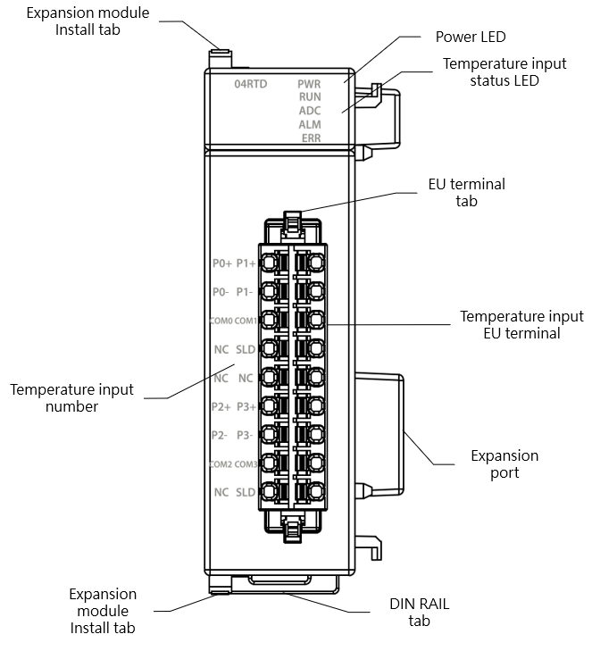
M04RTD Appearance
Technical Specification
M04RTD Technical Specifications Table
|
Item |
Technical Specification |
|
Model |
M04RTD |
|
Input Points |
4 |
|
Resolution |
0.1℃ |
|
Sampling cycle |
100ms/ch |
|
Temperature sensor type |
Pt100 / Pt1000: (-200~850℃) JPt100 / JPt1000: (-200~600℃) PT100(1000) – DIN EN 60751 JPT100(1000) – JIS C 1609-1981 |
|
Conversion precision |
±0.1% (25°C±5℃) ±0.5% (0~55℃) |
|
AD Converter |
24-Bit |
|
Operating mode |
PID Control ON/OFF Control |
|
Control cycle |
0.1~30 Second+ 1 Scan time |
|
Tuning |
PID Auto Tuning |
|
Insulation |
Between analog input and CPU:insulated(Digital isolators) Between analog input channels:insulated(optocoupler isolator) |
|
Operating Ambient Temperature |
0~55℃ |
|
Relative Humidity |
20 ~ 90% (non-condensing) |
|
Altitude |
≦2000m |
|
Vibration (Fixed by DIN RAIL) |
5~8.4Hz Amplitude: 3.5mm 8.4~150Hz Constant acceleration:19.6m/s^2(2G) 10G, 10 times each along the 3 axes (IEC61131-2 Standard) |
|
Shock |
10G, 3 times each along the 3 axes |
|
Noise Suppression |
1500Vp-p,Width 1us |
|
Withstand Voltage |
1500 VAC 1 minute (Between power terminals and input/output terminals, and between all external terminals and the housing) |
Status Indicator
M04RTD Status Indicator Table
|
Indicator |
instruction |
|
PWR Indicator |
Power ON: green light Power OFF: no light |
|
RUN Indicator |
Running: green light |
|
ADC Indicator |
ADC Converting: yellow light |
|
ALM Indicator |
On Alert: red light |
|
ERR Indicator |
In ERROR: red light |
Wiring
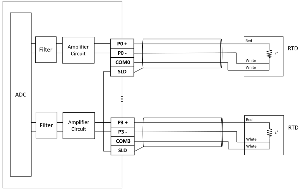
M04RTD Wiring
10-8 Temperature Combo Expansion Module Specifications
If the temperature input point of the M Series CPU module is not enough for a specific application, then can expand it with the additional expansion modules.
10-8-1 M0202TH Specification
Appearance and Function
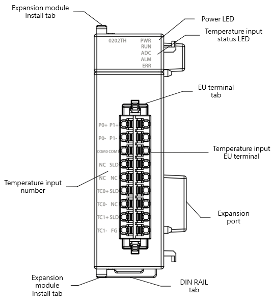
M0202TH Appearance
Technical Specification
M0202TH Technical Specifications Table
|
Item |
Technical Specification |
|
Model |
M0202TH |
|
TC Specifications |
|
|
Input Points |
2 |
|
Resolution |
0.1℃ |
|
Sampling cycle |
High Speed:200ms/ch Standard:400ms/ch |
|
Temperature sensor type |
K, J, E, T, R, B, N, S, mV |
|
Conversion precision |
±0.5% (25°C±5℃) ±1% (0~55℃) |
|
AD Converter |
24-Bit |
|
RTD Specifications |
|
|
Input Points |
2 |
|
Resolution |
0.1℃ |
|
Sampling cycle |
100ms/ch |
|
Temperature sensor type |
Pt-100, Pt-1000 (-200~850℃) JPt-100, JPt-1000 (-200~600℃) |
|
Conversion precision |
±0.1% (25°C±5℃) ±0.5% (0~55℃) |
|
AD Converter |
24-Bit |
|
Common Specifications |
|
|
Operating mode |
PID Control ON/OFF Control |
|
Control cycle |
0.1~30 Second |
|
Tuning |
PID Auto Tuning |
|
Insulation |
Between analog input and CPU:insulated(Digital isolators) Between analog input channels:insulated(optocoupler isolator) |
|
Operating Ambient Temperature |
0~55℃ |
|
Relative Humidity |
20 ~ 90% (non-condensing) |
|
Altitude |
≦2000m |
|
Vibration (Fixed by DIN RAIL) |
5~8.4Hz Amplitude: 3.5mm 8.4~150Hz Constant acceleration:19.6m/s^2(2G) 10G, 10 times each along the 3 axes (IEC61131-2 Standard) |
|
Shock |
10G, 3 times each along the 3 axes |
|
Noise Suppression |
1500Vp-p,Width 1us |
|
Withstand Voltage |
1500 VAC 1 minute (Between power terminals and input/output terminals, and between all external terminals and the housing) |
Status Indicator
M0202TH Status Indicator Table
|
Indicator |
instruction |
|
PWR Indicator |
Power ON: green light Power OFF: no light |
|
RUN Indicator |
Running: green light |
|
ADC Indicator |
ADC Converting: yellow light |
|
ALM Indicator |
On Alert: red light |
|
ERR Indicator |
In ERROR: red light |
Wiring
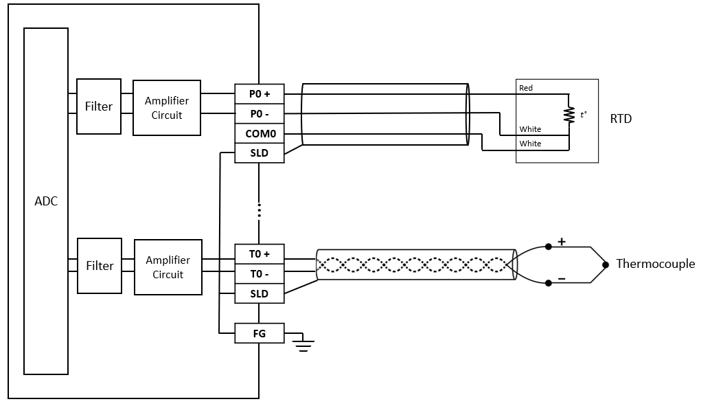
M0202TH Wiring
10-9 Load Cell Expansion Module Specifications
If the Load Cell input point of the M Series CPU module is not enough for a specific application, then can expand it with the additional expansion modules.
10-9-1 M02LC Specifications
Appearance and Function
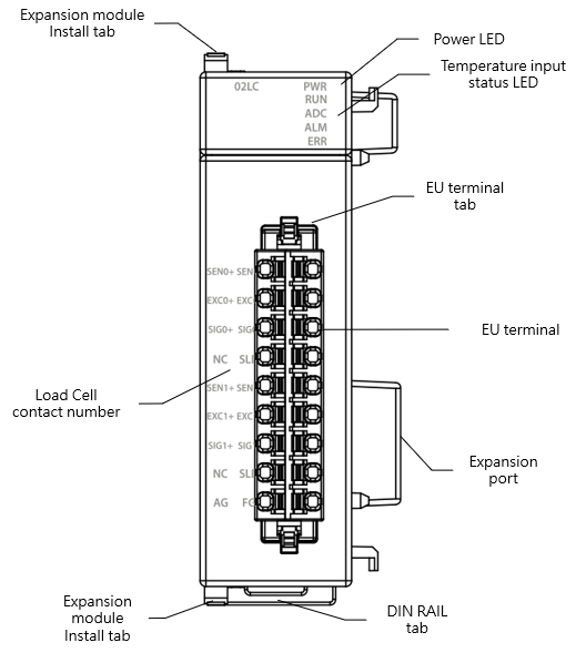
M02LC Appearance
Technical Specification
M02LC Technical Specifications Table
|
Item |
Technical Specification |
|
Model |
M02LC |
|
Input Points |
2 |
|
Excitation Voltage |
5VDC±5%, 60mA |
|
Sensor Type |
4-wire or 6-wire Load Cell |
|
Number of Sensor Connection |
4 * 350Ω Sensor |
|
Sensitivity |
±1.0mV/V |
|
AD Converter Resolution |
24-Bit |
|
Conversion precision |
±0.5% (25°C±5℃) |
|
Zero Drift |
0.2uV/℃ |
|
Gain Drift |
±10ppm/℃ |
|
Sampling cycle |
High Speed :2ms/ch. (only Use Single Point) |
|
Insulation |
Between analog input and CPU:insulated(Digital isolators) Between analog input channels:insulated(optocoupler isolator) |
|
Operating Ambient Temperature |
0~55℃ |
|
Relative Humidity |
20 ~ 90% (non-condensing) |
|
Altitude |
≦2000m |
|
Vibration (Fixed by DIN RAIL) |
5~8.4Hz Amplitude: 3.5mm 8.4~150Hz Constant acceleration:19.6m/s^2(2G) 10G, 10 times each along the 3 axes (IEC61131-2 Standard) |
|
Shock |
10G, 3 times each along the 3 axes |
|
Noise Suppression |
1500Vp-p,Width 1us |
|
Withstand Voltage |
1500 VAC 1 minute (Between power terminals and input/output terminals, and between all external terminals and the housing) |
Status Indicator
M02LC Status Indicator Table
|
Indicator |
instruction |
|
PWR Indicator |
Power ON: green light Power OFF: no light |
|
RUN Indicator |
Running: green light |
|
ADC Indicator |
ADC Converting: yellow light |
|
ALM Indicator |
On Alert: red light |
|
ERR Indicator |
In ERROR: red light |
Wiring
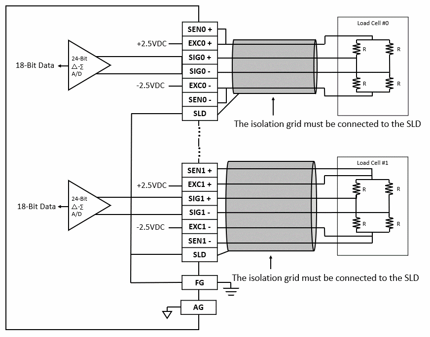
M02LC Wiring
10-9-2 M02LCR Specifications
Appearance and Function
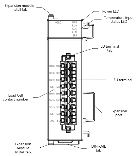
M02LC Appearance
Technical Specification
M02LCR Technical Specifications Table
|
Item |
Technical Specification |
|
Model |
M02LCR |
|
Input Points |
2 |
|
Excitation Voltage |
5VDC±5%, 60mA |
|
Sensor Type |
4-wire or 6-wire Load Cell |
|
Number of Sensor Connection |
4 * 350Ω Sensor |
|
Sensitivity |
±1.0mV/V |
|
AD Converter Resolution |
24-Bit |
|
Conversion precision |
±0.01% (25°C±5℃) ±0.4% (0~50°C) |
|
Zero Drift |
0.2uV/℃ |
|
Gain Drift |
±10ppm/℃ |
|
Sampling cycle |
Standard:10ms/ch |
|
Insulation |
Between analog input and CPU:insulated(Digital isolators, Transformer) Between analog input channels:insulated(optocoupler isolator) |
|
Operating Ambient Temperature |
0~55℃ |
|
Relative Humidity |
20 ~ 90% (non-condensing) |
|
Altitude |
≦2000m |
|
Vibration (Fixed by DIN RAIL) |
5~8.4Hz Amplitude: 3.5mm 8.4~150Hz Constant acceleration:19.6m/s^2(2G) 10G, 10 times each along the 3 axes (IEC61131-2 Standard) |
|
Shock |
10G, 3 times each along the 3 axes |
|
Noise Suppression |
1500Vp-p,Width 1us |
|
Withstand Voltage |
1500 VAC 1 minute (Between power terminals and input/output terminals, and between all external terminals and the housing) |
Status Indicator
M02LCR Status Indicator Table
|
Indicator |
instruction |
|
PWR Indicator |
Power ON: green light Power OFF: no light |
|
RUN Indicator |
Running: green light |
|
ADC Indicator |
ADC Converting: yellow light |
|
ALM Indicator |
On Alert: red light |
|
ERR Indicator |
In ERROR: red light |
Wiring
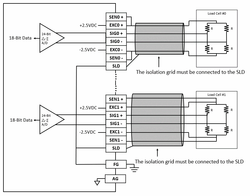
M02LCR Wiring
10-10 Repeater Expansion Module Specifications
If the power of the Power module is not enough for expansion module, then can expand it with the additional repeater Expansion module.
10-10-1 MRPWE-AC Specifications
Appearance and Function
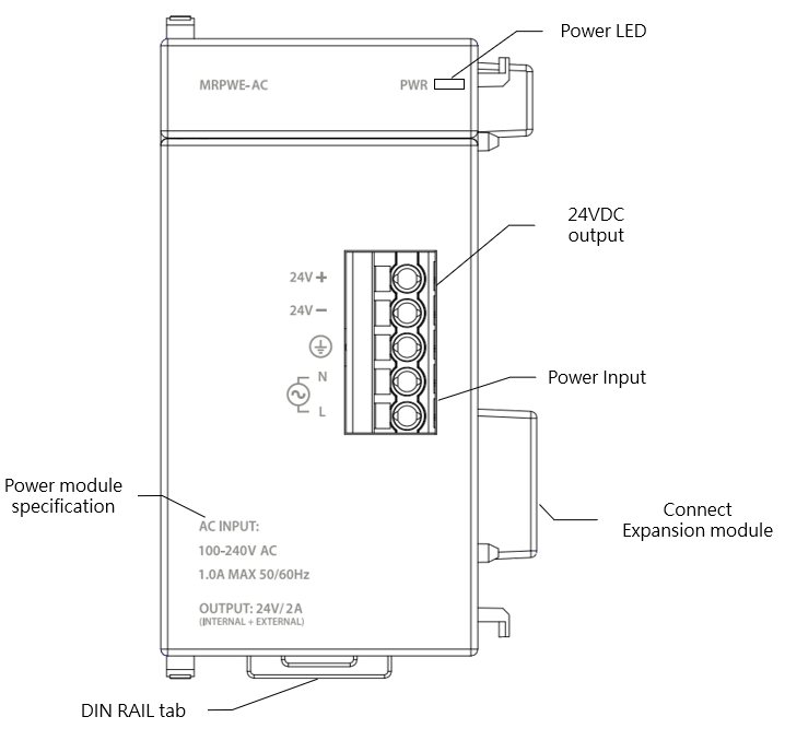
MRPWE-AC Appearance
Technical Specifications
MRPWE-AC Technical Specifications Table
|
Item |
Technical Specifications |
|
|
Model |
MRPWE-AC |
|
|
Input |
Input voltage |
100~240VAC |
|
Input frequency |
50/60Hz |
|
|
Maximum input current |
1A max. |
|
|
Inrush current(cold start) |
22A/115Vac (44A/230Vac) |
|
|
Withstand voltage |
3,000 VAC (Primary-secondary), 1,500 VAC (Primary-PE), 500 VAC (Secondary-PE) |
|
|
Insulation resistance |
>100MΩ/500VDC |
|
|
Fuse |
2A |
|
|
Hold-up time |
>15ms/ 115VAC,>60ms/ 220VAC |
|
|
Isolation Type |
Transformer/ Photocoupler Isolation,1500VAC/1 minute |
|
|
Power indication |
LED (green) |
|
|
output |
Rated output power |
48W (Shared CPU dedicated power supply and external Sensor power supply) |
|
Rated output current |
2A (Shared CPU dedicated power supply and external Sensor power supply) |
|
|
Output voltage range |
24VDC±1% |
|
|
Conversion efficiency |
86%/110VAC,87%/220VAC |
|
|
Protection |
Overvoltage protection |
Latching overvoltage protection, re-power on to recover 34V~36V |
|
Overcurrent protection |
Method: Foldback overload protection, automatically recover when overload is removed 101%~133% rated output power |
|
|
Operating Ambient Temperature |
0~55℃ |
|
|
Relative Humidity |
20 ~ 90% (non-condensing) |
|
|
Altitude |
≦2000m |
|
|
Vibration (Fixed by DIN RAIL) |
5~8.4Hz Amplitude: 3.5mm 8.4~150Hz Constant acceleration:19.6m/s^2(2G) 10G, 10 times each along the 3 axes (IEC61131-2 Standard) |
|
|
Shock |
10G, 3 times each along the 3 axes |
|
|
Noise Suppression |
1500Vp-p,Width 1us |
|
|
Withstand Voltage |
1500 VAC 1 minute (Between power terminals and input/output terminals, and between all external terminals and the housing) |
|
|
Certification |
CE |
|
Status Indicator
MRPWE-AC Status Indicator Table
|
Name |
instruction |
|
PWR LED |
Power ON: green light Power OFF: no light |
10-11 I/O Bus extension module Specifications
If extension expansion module to 2nd row, then can expand it with the additional I/O Bus extension module to Expansion module.
10-11-1 MRGH Specifications
Appearance and Function
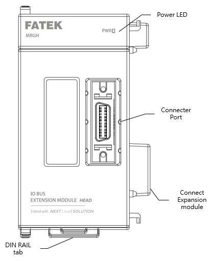
MRGH Appearance
Technical Specifications
MRGH Technical Specifications Table
|
Item |
Technical Specifications |
|
Model |
MRGH |
|
Function |
The head module must be used with the MRGT (tail). Each row can expand up to 16 Local I/O expansion modules, with a maximum of 6 rows (6 sections, racks), for a total of 64 expansion modules. |
|
Operating Ambient Temperature |
0~55℃ |
|
Relative Humidity |
20 ~ 90% (non-condensing) |
|
Altitude |
≦2000m |
|
Vibration (Fixed by DIN RAIL) |
5~8.4Hz Amplitude: 3.5mm 8.4~150Hz Constant acceleration:19.6m/s^2(2G) 10G, 10 times each along the 3 axes (IEC61131-2 Standard) |
|
Shock |
10G, 3 times each along the 3 axes |
|
Noise Suppression |
1500Vp-p,Width 1us |
|
Withstand Voltage |
1500 VAC 1 minute (Between power terminals and input/output terminals, and between all external terminals and the housing) |
|
Certification |
CE |
Status Indicator
MRGH Status Indicator Table
|
Name |
instruction |
|
PWR LED |
Power ON: green light Power OFF: no light |
10-11-2 MRGT Specifications
Appearance and Function
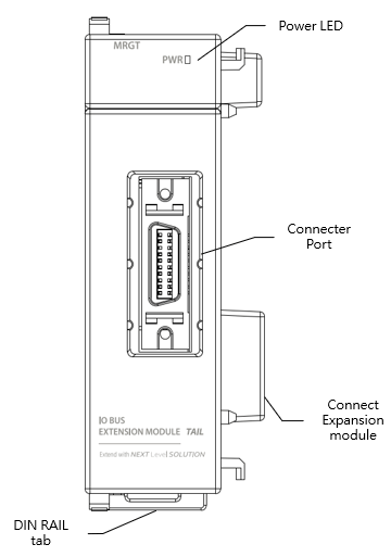
MRGT Appearance
Technical Specifications
MRGT Technical Specifications Table
|
Item |
Technical Specifications |
|
Model |
MRGT |
|
Function |
The tail module must be used with the MRGH (head). Each row can expand up to 16 Local I/O expansion modules, with a maximum of 6 rows (6 sections, racks), for a total of 64 expansion modules. |
|
Operating Ambient Temperature |
0~55℃ |
|
Relative Humidity |
20 ~ 90% (non-condensing) |
|
Altitude |
≦2000m |
|
Vibration (Fixed by DIN RAIL) |
5~8.4Hz Amplitude: 3.5mm 8.4~150Hz Constant acceleration:19.6m/s^2(2G) 10G, 10 times each along the 3 axes (IEC61131-2 Standard) |
|
Shock |
10G, 3 times each along the 3 axes |
|
Noise Suppression |
1500Vp-p,Width 1us |
|
Withstand Voltage |
1500 VAC 1 minute (Between power terminals and input/output terminals, and between all external terminals and the housing) |
|
Certification |
CE |
Status Indicator
MRGT Status Indicator Table
|
Name |
instruction |
|
PWR LED |
Power ON: green light Power OFF: no light |
Tip: press ← → to switch chapters, Ctrl+K to search