5-1 The Principle and the Structure of Interrupt Function
There are many jobs that M-Series PLC needs to carry out. For example, there are at least 20k words user’s program need to be solved, 1024 points of I/O status need to be captured or updated, many communication ports need to be serviced, and etc. However, jobs can only be executed one at a time as there is merely one CPU available. Therefore, PLC service one job after another in sequence until all the jobs are executed once. Then, it will return to the first job to repeat the same cycle. The time interval of each execution is called the “scan time” of PLC. The CPU execution speed is extremely fast in comparison with human response. As far as human feeling is concerned, PLC almost completes all jobs at the same time when PLC can normally complete the foregoing huge workload within tens of milliseconds(ms). Hence, it can meet the requirements of the most practical control cases.
In most application cases, the control method described above is very much sufficient. But for some applications that require a high-speed response (such as positioning control), a delay in scan time will certainly mean an increase in error. Under the circumstances, only applying the “Interrupt” function can achieve the precision requirement.
The so-called “Interrupt” means the interrupt request to the CPU during normal scan cycle when an immediate response is required. After receiving such request, the CPU will promptly stop all scanning work to prioritize to perform and complete the corresponding service work before return (the so-called “Return from Interrupt” or RTI) to where interrupt occurred and resume the interrupted scanning work.
The service work needed to carry out while interrupt occurred is called Interrupt Service Routine, which is a subroutine consisted by a series of ladder codes. It is placed in the subroutine area and begin with the LBL instruction with reserved label name (please refer to Section 5.3). Since it is placed in the subroutine area, it will not be executed in a normal PLC scanning cycle (PLC only constantly scans the main program area but not the subroutine area).
In normal case, the CPU can promptly execute the corresponding interrupt routine within hundreds of micro-seconds when an interrupt occurred. When there are more than one interrupt occurred at the same time (i.e., M-Series PLC has 36 interrupts source), only the interrupt with highest priority can be executed. All the other interrupt routines need to wait until it became the highest priority among the pending interrupts. Consequently, a response delay of hundreds of microseconds, or even few milliseconds, may be caused. Hence, in a multiple interrupt inputs structure, an interrupt priority is given to each interrupt in accordance with its importance. In case another interrupt request is made when the PLC is carrying out the interrupt service routine for an interrupt request that has a higher priority than the new interrupt request, the CPU will wait until the execution of the subroutine is completed before accepting the new interrupt request. However, if the priority of the new interrupt request is higher than the one being executed, the CPU will stop the running of the current interrupt service routine immediately to execute the interrupt service routine with a higher priority. After completing the execution, the CPU will return to the previously interrupted service routine with a lower priority to continue the incomplete work. This kind of interrupt in an interrupt execution is called the “Nested Interrupt”.
5-2 Structure and Application of Interrupt Service Routine
Although both “Interrupt” and “Call” are having subroutines, but the calling methods (to jump to subroutine for execution) are different. When the CALL command [FUN67] is executed by “Call” in the main program, the CPU will execute the subroutine with the label name designated by the CALL command. The CPU will return to the main program after the RTS (Return from Subroutine) command is executed.
The calling of “Interrupt” is triggered by, instead of using software commands, the hardware interrupt signal to the CPU. The CPU will identify the source of the interrupt and jump automatically to the “Interrupt Service Routine” with the label name of the interrupt in the subroutine for execution. It will return to the main program after the RTI (Return from Interrupt) command is executed. Therefore, there is no ladder code relevant to interrupt in the main program area.
|
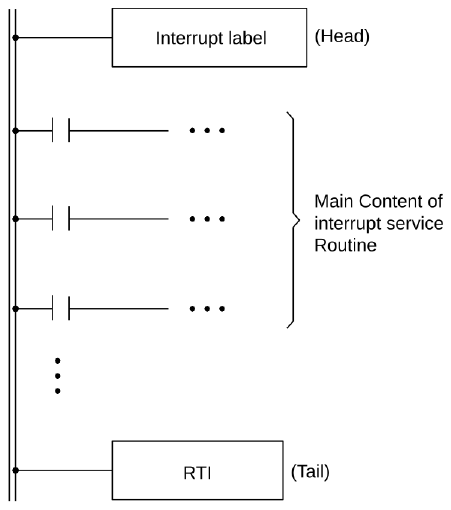
As mentioned before, interrupt service routine must be placed in the sub program area. The structure is shown as the diagram on the right where a “head”, a “tail” and the main body of the service routine are included. The “head” is the “interrupt label name” of the interrupt (to be discussed in the next section). The “tail” is the RTI command [FUN69], to tell the CPU that the interrupt subroutine is ended and it should jump to the place where were interrupted, please refers to FUN69 (RTI) instruction. In between the “head” and the “tail” is the main body of the interrupt service routine used to tell the CPU what control actions should be executed when interrupt occurs. |
The power line for subroutine is indicated by double lines to differentiate from the power line for the main program (single line) for easy reading. Figure 12 Interrupt Service Routine |
5-3 Interrupt Source, Label and Priority
As described in the last section, every “Interrupt Service Routine” should have a unique “Interrupt Label”. There are “Interrupt Labels” for interrupts, namely “Interrupt Reserve Words “in UperLogic, can be used in the sub program area of M-Series PLC. These labels are dedicated to the interrupt routines hence cannot use for normal subroutine or jump target.
The “Interrupt Label” (Interrupt Reserve Words) are all suffix with an “I” letter. For examples, the interrupt label for high-speed counter HSC0 should be “HSC0I” and the interrupt label for X0+ should be “X0+I”. The “Interrupt Labels” and their priorities for M-Series PLC interrupt sources are shown as below.
The following table is the interrupt sources and their label names, the principle of use is to use STM0I~STM3I, X0+I~X7 first。
The smaller the priority value, the higher the priority of the interrupt source or tag.
|
Suspension source |
Priority |
Suspension marking |
Conditions |
Remark |
|
|
Hardware timing base |
3 |
STM0I |
Interval: 1ms–60000ms |
Time unit: 1ms |
|
|
3 |
STM1I |
Interval: 1ms–60000ms |
|||
|
3 |
STM2I |
Interval: 1ms–60000ms |
|||
|
3 |
STM3I |
Interval: 1ms–60000ms |
|||
|
3 |
LTM0I |
Interval: 10ms–60000ms |
Time unit: 10ms |
||
|
3 |
LTM1I |
Interval: 10ms–60000ms |
|||
|
3 |
LTM2I |
Interval:10ms–60000ms |
|||
|
3 |
LTM3I |
Interval:10ms–60000ms |
|||
|
HSC |
2 |
HSC0I |
HSC0 to (CV=PV) |
||
|
2 |
HSC1I |
HSC1 to (CV=PV) |
|||
|
2 |
HSC2I |
HSC2 to (CV=PV) |
|||
|
2 |
HSC3I |
HSC3 to (CV=PV) |
|||
|
HST |
1 |
HST0I |
HST0 to (CV=PV) |
Time unit: 100us |
|
|
1 |
HST1I |
HST1 to (CV=PV) |
|||
|
1 |
HST2I |
HST2 to (CV=PV) |
|||
|
1 |
HST3I |
HST3 to (CV=PV) |
|||
|
Digital input |
2 |
X0+I (INT0+) |
X0 Positive edge triggered |
||
|
2 |
X0−I (INT0-) |
X0 Negative edge triggered |
|||
|
2 |
X1+I (INT1+) |
X1 Positive edge triggered |
|||
|
2 |
X1−I (INT1-) |
X1Negative edge triggered |
|||
|
2 |
X2+I (INT2+) |
X2 Positive edge triggered |
|||
|
2 |
X2−I (INT2-) |
X2 Negative edge triggered |
|||
|
2 |
X3+I (INT3+) |
X3 Positive edge triggered |
|||
|
2 |
X3−I (INT3-) |
X3 Negative edge triggered |
|||
|
2 |
X4+I (INT4+) |
X4 Positive edge triggered |
|||
|
2 |
X4−I (INT4-) |
X4 Negative edge triggered |
|||
|
2 |
X5+I (INT5+) |
X5 Positive edge triggered |
|||
|
2 |
X5−I (INT5-) |
X5 Negative edge triggered |
|||
|
2 |
X6+I (INT6+) |
X6 Positive edge triggered |
|||
|
2 |
X6−I (INT6-) |
X6 Negative edge triggered |
|||
|
2 |
X7+I (INT7+) |
X7 Positive edge triggered |
|||
|
2 |
X7−I (INT7-) |
X7 Negative edge triggered |
|||
|
Digital input |
X8+I(INT8+) |
X8 Positive edge triggered |
|||
|
X8-I(INT8-) |
X8 Negative edge triggered |
||||
|
X9+I(INT9+) |
X9 Positive edge triggered |
||||
|
X9-I(INT9-) |
X9 Negative edge triggered |
||||
|
X10+I(INT10+) |
X10 Positive edge triggered |
||||
|
X10-I(INT10-) |
X10 Negative edge triggered |
||||
|
X11+I(INT11+) |
X11 Positive edge triggered |
||||
|
X11-I(INT11-) |
X11 Negative edge triggered |
||||
|
X12+I(INT12+) |
X12 Positive edge triggered |
||||
|
X12-I(INT12-) |
X12 Negative edge triggered |
||||
|
X13+I(INT13+) |
X13 Positive edge triggered |
||||
|
X13-I(INT13-) |
X13 Negative edge triggered |
||||
|
X14+I(INT14+) |
X14 Positive edge triggered |
||||
|
X14-I(INT14-) |
X14 Negative edge triggered |
||||
|
X15+I(INT15+) |
X15 Positive edge triggered |
||||
|
X15-I(INT15-) |
X15 Negative edge triggered |
||||
|
X16+I(INT16+) |
X16 Positive edge triggered |
||||
|
X16-I(INT16-) |
X16 Negative edge triggered |
||||
|
Digital input |
X17+I(INT17+) |
X17 Positive edge triggered |
|||
|
X17-I(INT17-) |
X17 Negative edge triggered |
||||
|
X18+I(INT18+) |
X18 Positive edge triggered |
||||
|
X18-I(INT18-) |
X18 Negative edge triggered |
||||
|
X19+I(INT19+) |
X19 Positive edge triggered |
||||
|
X19-I(INT19-) |
X19 Negative edge triggered |
||||
|
X20+I(INT20+) |
X20 Positive edge triggered |
||||
|
X20-I(INT20-) |
X20 Negative edge triggered |
||||
|
X21+I(INT21+) |
X21 Positive edge triggered |
||||
|
X21-I(INT21-) |
X21 Negative edge triggered |
||||
|
X22+I(INT22+) |
X22 Positive edge triggered |
||||
|
X22-I(INT22-) |
X22 Negative edge triggered |
||||
|
X23+I(INT23+) |
X23 Positive edge triggered |
||||
|
X23-I(INT23-) |
X23 Negative edge triggered |
||||
5-4 How to use Interrupt Function?
Whether internal timing suspension, external input suspension or HSC/HST interruption, a similar operating method will be used. Because a dedicated section is provided for describing the operation method of HSC/HST, this section shall provide the example in order to explain internal timing suspension and external input suspension.
|
Start |
|||
|
Set up the Interrupt value in Main Program Field: For example, set the STM0 cycle as R35435. |
For special register, please refer to Appendix A, |
||
|
In Main Program Field, trigger the Interrupt of special relay; for example, set STM0 as M9166. |
For special register, please refer to Appendix A, |
||
|
In sub-program field, write the service Interrupt program. |
please refer to Section 5.6 |
||
|
End |
|||
Figure 13 The configuration of time-setting interrupt
|
Start |
|||
|
Set up the suspended configuration |
Please refer to Section 5.5 |
||
|
In sub-program field, write the service suspension program |
Please refer to Section 5.6 |
||
|
End |
|||
|
Figure 14 The configuration of external interrupt |
|||
5-5 Configuring the Interrupt Function
In fact, the interrupt configuration means the application regarding whether certain interrupt functions should be used or not.
The interrupt configuration comprises the I/O relevant configuration and the I/O irrelevant configuration. When using the I/O relevant HSC/HST and external interrupt, activate the corresponding I/O interrupt in the I/O configuration of the UperLogic. After being configured, the system will trigger the Enable to suspend such device.
As for the “internal timing interrupt” irrelevant to I/O, the system will regard it that such interrupt function is being planned when the interrupt-running sub-program is enabled by the “Timing interrupt” wording that will be displayed in the sub-program field. In this case, set the interrupt cycle with Special Register and then enable the interrupt function by triggering the corresponding Special Relay. The value required for setting up the interrupt of Special Register cannot be written after Special Relay is triggered. Therefore, it should be changed before triggering the relay.
5-5-1 Example of Interrupt Configuration
In project window, click “I/O Configuration Setup”: Project Name
System configuration
I/O configuration 🡪 Select “interrupt setup”
After displaying the “Interrupt setup” picture, you may click the external input that will be suspended in the window.
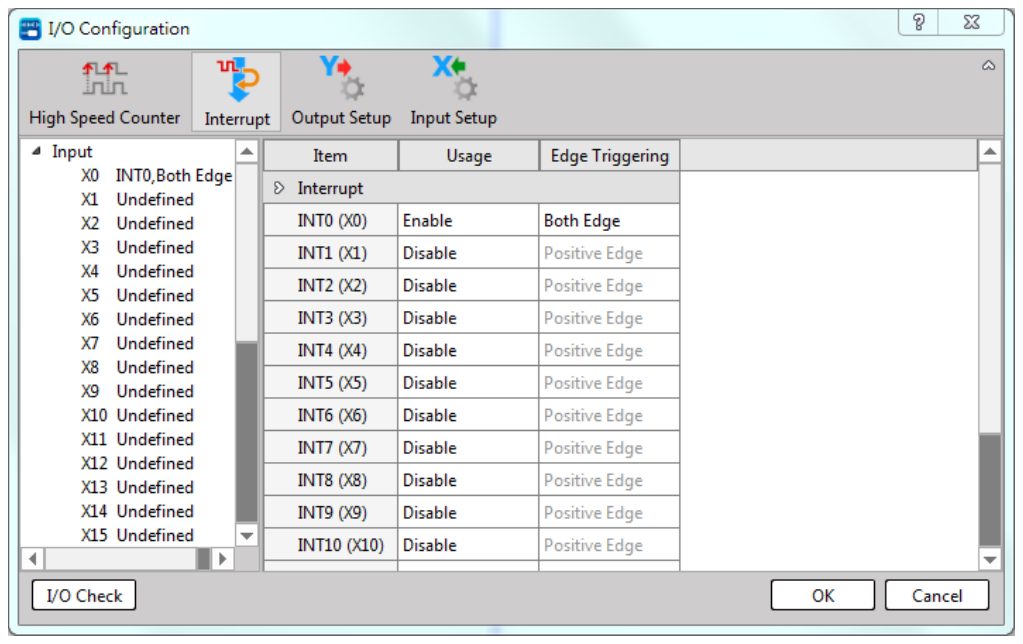
Figure 15 Interrupt Configuration
5-6 Type of Interrupt Function
5-6-1 Hardware timing base
The hardware time base comprises 1ms STM, 10ms LTM, 0.1ms graduation of High-speed Timer HST and a 32-bit cycle timer. In addition to the cycle timer, other hardware timing bases support interrupts, and can be turned on or off by calling the EN (FUN145) and DIS (FUN146) commands (after setting its special relay, the default is on). Interrupts are used by triggering their corresponding special relays. According to the period value of the register corresponding to the timing base, the interrupt program is executed periodically; the current timing register is also provided as a program or monitoring. See Section 8.2 for details.
Time-setting Timer STM
Totaling 4 of 16-bit timer, time unit: 1ms.
Time-setting Timer LTM
Totaling 4 of 16-bit timer, time unit: 10ms.
High-speed Timer HST
Totaling 4 of 32-bit high-speed timer, time unit: 0.1ms.
Cycle Timer HSTA
Totaling 1 of 32-bit cycle timer, time unit: 0.1ms.
5-6-2 High-speed Counter HSC
M-Series PLC supports the Hardware High-Speed Counter (briefed as HHSC) configured by hardware circuit. Such HHSC can read the high-speed signal that cannot be achieved by conventional counters. In this regard, M-Series PLC provides 4~8 HHSCs depending on the series, and they are serving as 32-bit high-speed counters (HSC0–HSC7). For details, please refer to Section 8.1.
5-6-3 External Interrupt
The external interrupt is mainly used in the application that needs to be executed or reflected within a very short period of time when receiving the external signal from the PLC. When compared to general input, the external interrupt may vary according to the program scanning time. The system can execute the content of externally imported interrupt within a very short period of time in order to achieve the control action such as stopping the motor immediately when the motor reaches the intended position.
- Once completing the interrupt configuration, it cannot be changed during the PLC RUN process. In spite of this, M-Series PLC provides EN command (FUN145) and DIS command (FUN146) to allow or prohibit the external interrupt and the HSC interrupt so as to control the change flexibly during the PLC RUN process. Please refer to the description of the aforesaid two commands.
5-7 Example of Interrupt Program
Regarding the content of interrupt, following suggestions are provided as a reference for users:
- The content of the suspended program should be short and concise in order to improve the PLC efficiency.
- The efficiency of the M PLC is very high. The user program of a general application usually takes only 1~single digit milliseconds to execute. Therefore, if the application can tolerate a few millisecond variations for a specific time interval difference, consider calling Timer in the main program. And in the main program "time up" event occurs in the way of re-calling the sub-program. In this way, the CPU can be switched due to the removal of interrupts, and the overall program performance can be improved.
- The Jump and Label commands can be used in the suspended program for jumping alternately in the suspended program. However, you cannot jump from Main Program or Sub-program to the suspended Label or jump from the suspended content to the Main Program or Sub-program Label. Indicated below is the concept diagram:
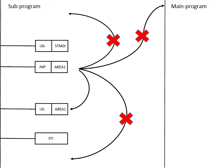
Figure 16 Using JUMP in an interrupt program
Example 1
Example of position precision control for desired contact by suspending “X0+” with external hardware:
X0: Detects the position of sensor
X1: Emergency stop
Y0: Controlling motor
【External interrupt configuration】
|
【INT : X0+】 |
During the configuration, input X0 and then issue the interrupt signal when 0→1 |
【Main Program】

M0 (Enable). When 0→1, the Controlling Motor is ON.
【Sub-program】
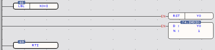
When Sensor X0 detects that the command reaches the detected position. i.e., when X0 becomes 0→1 and the hardware will execute such Interrupt Sub-program automatically.
When the Controlling Motor changes from Y0 to 0, the system will stop the motor immediately.
In the interrupt sub-program, you need to issue the Input/Output command immediately in order to achieve the real-time high-speed precision control effect.
Example 2 1ms internal timing interrupt
【Main Program】
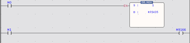
When M0=1, set the interrupt cycle of STM0 as 1ms. After R35435=1 and M1=1, the STM0 will execute timing interrupt once every 1ms.
【Sub-program】

After enabling 1ms timing suspension, the system will run such suspension sub-program every 1ms automatically.
R0 serves as the up-cycle timer of 1ms time base.
R1 serves as the down-cycle timer of 1ms time base.
Tip: press ← → to switch chapters, Ctrl+K to search