11-1 Setting the Network Interface
Default parameter of network interface
|
Address |
Content |
|
|
IP Address |
192.168.2.4 |
|
|
Sub-net Mask |
255.255.255.0 |
|
|
Gateway Preset |
192.168.2.1 |
|
|
DNS Primary Address |
1.1.1.1 |
|
|
DNSS Secondary Address |
8.8.8.8 |
|
Setting network interface through software:
- Open UperLogic software and then set up the connection between PC and PLC. Click “Connection Parameter” in PLC tag.

Figure 63 “Connection Parameter” under PLC tag
- Select the USB type that will be connected.
- Connection test: Check if the connection is normal while displaying the required information such as the connected model and firmware version, etc.
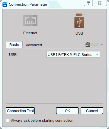
Figure 64 Connection Parameter
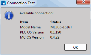
Figure 65 Connection Test
- Click “Ethernet Configuration” and the Ethernet setup window will appear. At this time, you may start setting the PLC IP address, sub-net mask, gateway preset and DNS service as well as selecting the need of using the DHCP function. You also can set up the primary and secondary ports of FATEK and Modbus TCP communication protocols.
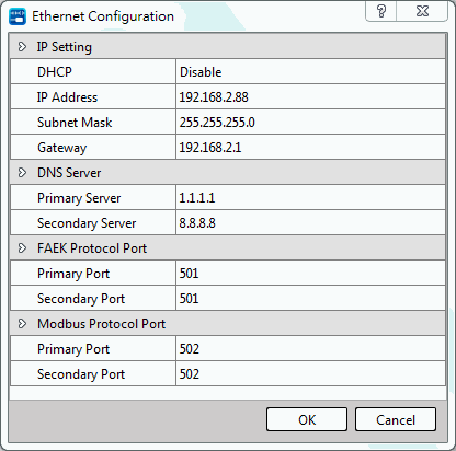
Figure 66 Setting of Ethernet
6. Click “OK” and then the system will start writing in the PLC.
The network interface setting through the registers:
|
Special Register No. |
Description |
|
R35382 |
CPU Unit IP address OCT1 (Leading) |
|
R35383 |
CPU Unit IP address OCT2 |
|
R35384 |
CPU Unit IP address OCT3 |
|
R35385 |
CPU Unit IP address OCT4 |
|
R35386 |
CPU Unit Sub-net Mask OCT1 (Leading) |
|
R35387 |
CPU Unit Sub-net Mask OCT2 |
|
R35388 |
CPU Unit Sub-net Mask OCT3 |
|
R35389 |
CPU Unit Sub-net Mask OCT4 |
|
R35390 |
CPU Unit Gateway OCT1 (Leading) |
|
R35391 |
CPU Unit Gateway OCT2 |
|
R35392 |
CPU Unit Gateway OCT3 |
|
R35393 |
CPU Unit Gateway OCT4 |
|
R35394 |
CPU Unit Primary DNS Server OCT1 (Leading) |
|
R35395 |
CPU Unit Primary DNS Server OCT2 |
|
R35396 |
CPU Unit Primary DNS Server OCT3 |
|
R35397 |
CPU Unit Primary DNS Server OCT4 |
|
R35398 |
CPU Unit Secondary DNS Server OCT1 (Leading) |
|
R35399 |
CPU Unit Secondary DNS Server OCT2 |
|
R35400 |
CPU Unit Secondary DNS Server OCT3 |
|
R35401 |
CPU Unit Secondary DNS Server OCT4 |
|
Special Contact No. |
Description |
|
M9164 |
Network interface restarting |
|
M9165 |
DHCP enable |
|
Special Register No. |
Description |
|
R35481 |
FATEK M1 Communication Protocols Port |
|
R35482 |
Modbus TCP Communication Protocols Port |
When using the register to set up the Ethernet IP address, please execute the following procedure:
To set the IP address of the PLC as “192.168.0.152”:
- If the IP address of the original Ethernet of the CPU Unit is “192.168.0.150”, check the value of special registers R35382–R35385 on the monitoring page, i.e., R35382=192, R35383=168, R35384=0 and R35385=150, as per below.
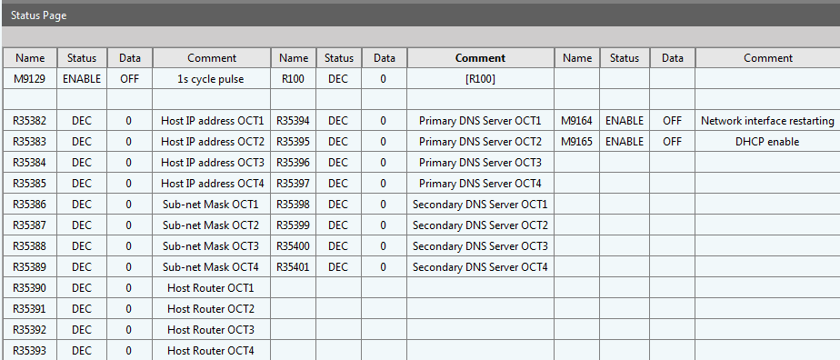
Figure 70 Values of R25382~R35383 special registers on status page
- Change the values of R35382–R35385 special registers as follows:
R35382=192, R35383=18, R35384=0 and R35385=152, as per the figure below.
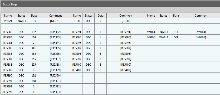
Figure 71 Modifying values of R25382~R35383 special registers
- Run M9164 for one pulse and then write the value of special register on Ethernet in the PLC in order to establish the changed IP address. At this time, you have completed the setting of Ethernet IP address for M-PLC with the register.
- Note: M9164 is designed in resetting type. After being set as “ON”, it will be restored automatically.
11-2 FATEK Searching Protocols
When there is more than one CPU Unit in the same network domain, users need a method to make it easier to maintain on CPU Units with different purposes. This is the purpose of the FATEK Searching Protocols. You can use the software to search for CPU Units in the current domain, obtain the main information of each CPU Unit, and directly connect to the target CPU Unit.
Execute the function of searching on network through software:
- Open UperLogic and then click “Connection Parameter” in PLC tag.

Figure 72 “Connection Parameter” in PLC tag
- Click “Ethernet” in “Connection Parameter”.
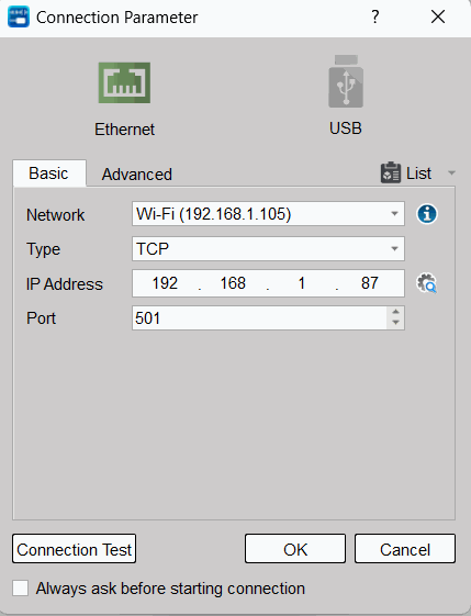
Figure 73 Click “Ethernet”
- Click “Search”.
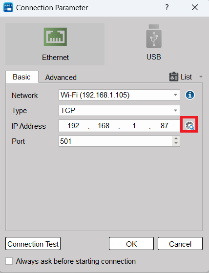
Figure 74 Network searching
- Click “Scan”, and the CPU Units in the same domain that support the FATEK searching protocol will appear, and their IP (name), MAC address, and mode information will be displayed.
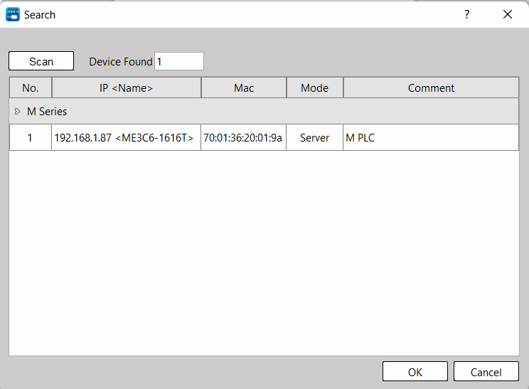
Figure 75 Click “Scan”
- To connect with the PLC of other unit, click the PLC of that unit and then press “OK” and the connection parameter will be set as the IP address of the respective PLC automatically.
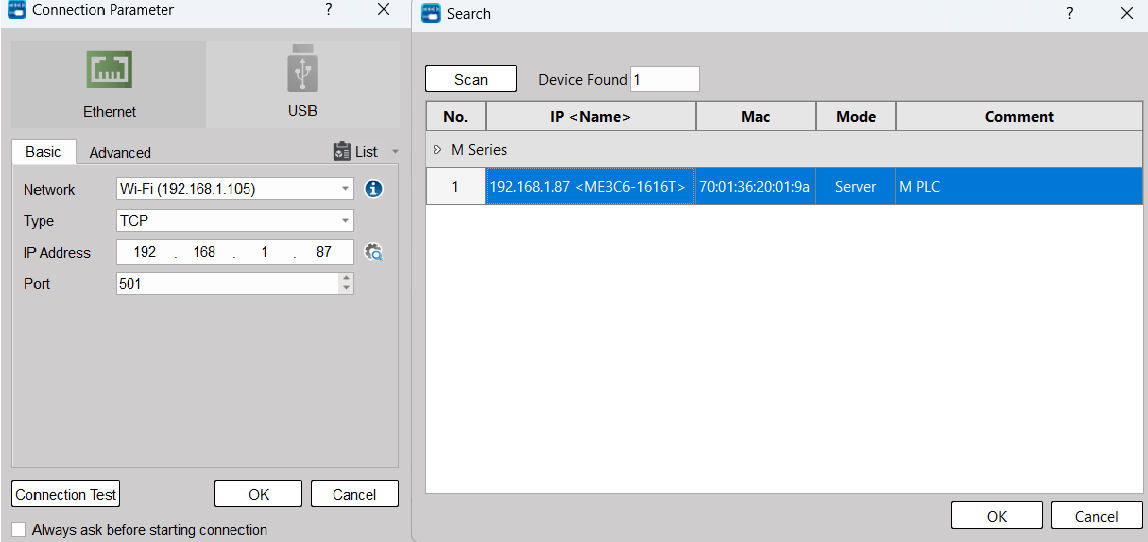
Figure 77 CPU Unit connection
11-3 NTP Time Synchronization
The purpose of NTP time synchronization function is to avoid the trouble of manual time calibration regularly for the PLC to execute the time synchronization through the network and the appointed server in order to achieve more efficient time calibration and synchronization for the equipment.
Setting and description of NTP time synchronization function:
- Open UperLogic and click the “Server Configuration” in “Project” tag or click “Server Configuration” in “Project management”.
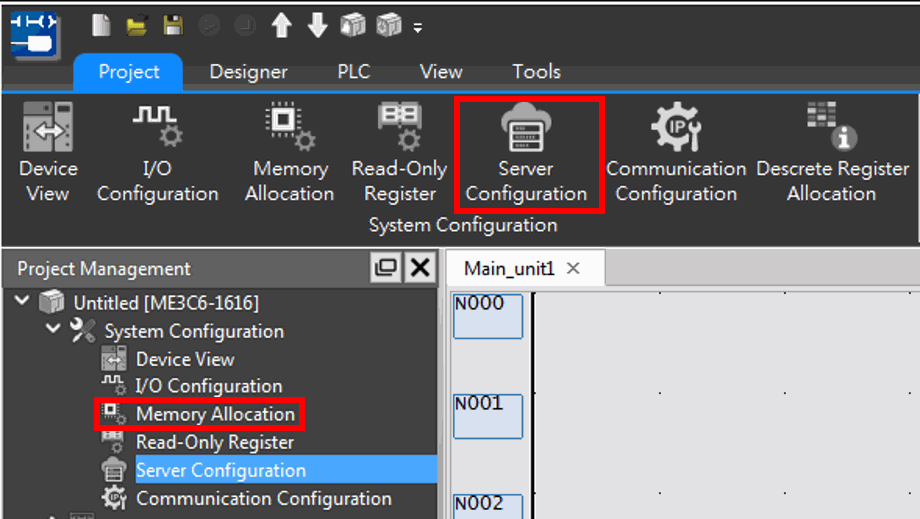
Figure 78 Click “Server Configuration” in “Project”.
- After that, the system will show the “Server Configuration” dialogue window as per below:
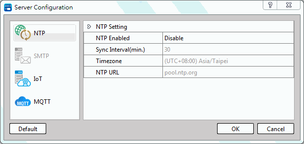
Figure 79 Server setting
- Click the left-side “NTP” function option and the right-side is the function setting.
- Select the “NTP Enabled” option as “Enable” and then set “Sync Interval”, “Timezone” and “NTP URL”. Finally, download the project to PLC to complete the setting process.
- If the PLC network maintains normal communication after downloading the project to PLC, the system will execute the first round of time synchronization and then follow the programmed synchronization interval. If the PLC network is operating unstably from the very beginning, then it will execute the synchronization during the next round of synchronization interval.
|
Option |
Description |
|---|---|
|
NTP Enabled |
Click the NTP time synchronization function to see if it is enabled. |
|
Sync Interval |
To set the synchronous time; the unit will be expressed in minutes. |
|
Timezone |
Set according to the time zone where the application is located. The example shown is Taipei GMT+08:00 and it means that the time zone in Taipei will be GMT+8 hours. |
|
NTP URL |
The website where the network time-setting server (NTP server) is installed. |
Table 22 Description table of NTP setting options
11-4 Publishing/ Subscribing MQTT
The MQTT serves a kind of communication protocol designed for the IoT. Being simple and compact, it is suitable for applying in an environment where the hardware resources and the network bandwidth are restricted in order to satisfy the remote monitoring and data swapping demands.
The message transmission mechanism is designed in publishing/subscribing mode. Each individual message should be assigned with a subject name for easier identification such as temperature. The Client end is acting the publisher and subscriber role in which, the Publisher is liable for publishing the subject-affixed message and the Subscriber is playing the role of subscribing the subject. The server end serves as a Broker to receive the message from the Publisher and then transfer to the Subscriber asking for the subject.
The MQTT function triggered by the M-Series CPU Units can play the aforesaid 3 roles concurrently, i.e., Publisher, Subscriber and Broker. Through MQTT function, M-Series CPU Units will be allowed to publish the register address of the device (HMI, PLC) to the Broker on the network; in the meantime, it also connects the subject data to be subscribed by the Broker and then read and write such data in the register address. Further, the M SERIES PLC can also use the built-in Broker directly without the need of searching for another Broker tool.
This chapter will describe the MQTT related pages and setting method.
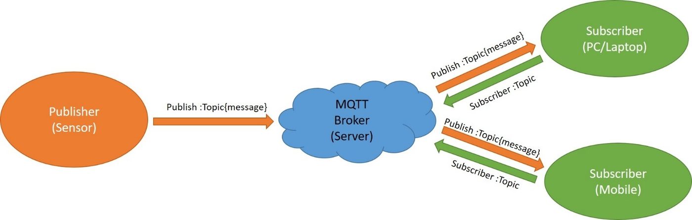
Figure 80 Schematic diagram of MQTT application
11-4-1 Server configuration
To use the MQTT function, click “MQTT” from the “Server Configuration” window in the left-side “Project” and you will be allowed to access the setup page. The “Server” page can be used to set the MQTT Server (Broker), as per the figure below:
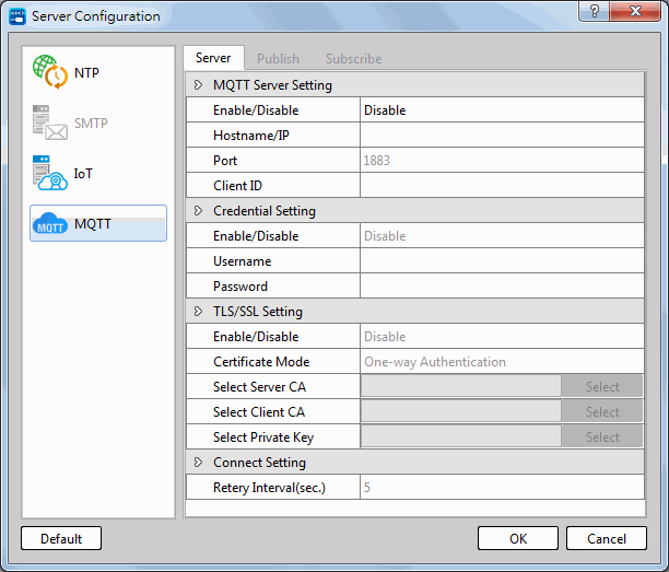
Figure 81 Setting window of MQTT Server
|
Column |
Description |
|
【Set MQTT server】 |
【Enable/ Disable】 For selecting to see if to enable “MQTT” and it is serving as the main switch of the “MQTT” function. After being enabled, you will be allowed to set the detail column and use the desired “Subject publishing” and “Subject subscribing” pages. 【Host (IP or domain name)】 To set the Broker host address, you may log in the IP or domain name and then it will be preset as “127.0.01”. 【Port No.】 To set the Broker connection port. Preset as “1883”. 【Client ID】 The ID specially owned by the Client. It can be set privately and you may use special code bearing “%” prefix to combine them into unique ID: %1: HMI name %2: Random code %%: Bit % |
|
【ID verify】 |
【Enable/Disable】 For selecting to see if MOTT Broker ID should be used. The Broker to be connected has been set with an ID. You may input the following items here: 【User name】 Input the username appointed by the Broker. 【Password】 Input the password appointed by the Broker. After that, it will be protected with the encryption code. |
|
【TLS/SSL】 |
【Enable/Disable】 For selecting to see if the TLS/SSL function of MQTT should be used 【Certification Mode】 For selecting to see if it belongs to one-way verification or two-way verification function. The Broker to be connected has been set with TLS/SSL encrypted message transmission function. You may import the certification file here. 【Select server certificate】 When using server certification method, “import” the required certificate. 【Select Client certificate】 Use the Client certification method in order to “import” the required certificate. 【Select private key】 For selecting the private key to be used. |
Table 23: Properties for setting MQTT Server page
11-4-2 Topic Publish
To use the MQTT function, click “MQTT” from the “Server Configuration” window in the left-side “Project” and then select “Enable” to show the “Topic Publish”. Next, click the upper-left “Add” button to add a new subject. By clicking “Delete” button, you may delete the selected subject. By clicking “Edit” or double clicking the item in the Topic List, you may edit the selected topic. If the Topic List contains the existing items, you may click “Export” and all of the topic data will be exported for creating the specific-format CSC file. By clicking the “Import” button, you may import the specific-format CSC file for updating the topic table. In Topic List, the left-side of each topic is provided an exclusive ID and it will be used as the topic ID.
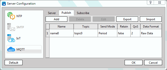
Figure 82 Topic setting of publishing MQTT topics
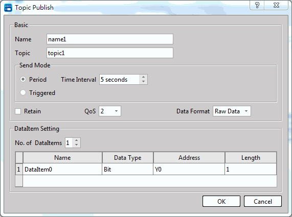
Figure 83 Topic publish of MQTT
|
Column |
Description |
||||||||
|
【Basic】 |
【Name】 For setting the topic name and it can be used to describe the name. 【Topic】 The topic when MQTT is transmitting the message. (Notice: “#” and “+” are wildcard characters and they should not be used). 【Transmission Mode】 a. 【Cyclic】 Transmitting the message periodically and it can be used to set the interval second duration. b. 【Value change trigger】 The system will transmit the message when the value of the figure data item has changed. 【Retain message】 For determining if the MQTT message should be retained in the server. If selecting this item, the server will preserve such subject message. If a new subscriber is required or when the interrupted subscriber should be reconnected, then they will receive the latest message being retained. 【QoS】 For setting the Quality of Service of MQTT, and it comprises the following 3 classes:
【Data format】 The message content of each individual subject is composed of the address values of the figure data item, as per below: 【Raw Data】 01 2a 03 b8 1e e5 3f 6c 6f 76 65 Note: 【JSON】 { "d": { "DataItem0": [true, true], "DataItem1": [810, 793, 688], "DataItem2": [1.789, 3.51], "DataItem3": ["love"] }, "error": [], "ts": "2019-06-18T10:55:41.491" } 【Custom】 User-defined Text using %1, %2, … variables to incorporate register or relays. Note:
|
||||||||
|
【Set figure data item】 |
【Number of figure data item】 Set the number of figure data item required for such topic. Described below is the detailed setting of figure data item. 【Name】 The name of figure data item cannot be left blank and the name of each item must be unique and exclusive. The user shall be allowed to input the item name directly. 【Type of figure data】 It comes with 【bit】, 【16-bit BCD number】, 【16-bit positive integer】, 【32-bit BCD number】, 【32-bit integer】, 【32-bit positive integer】, 【32-bit floating point number】 and 【Ascii (U.S.)】 for option. 【Address】 Based on the type of figure data, the user will be allowed to set the address for each individual figure data item. 【Length】 If the type of figure data is configured in 16-bit, it will occupy one byte and 32-bit will occupy two bytes. In case of Ascii-String, it allows the user to determine the number of bytes that will be occupied by the figure data item. Each individual byte can accommodate 2 bits. |
11-4-3 Topic Subscribe
To use the MQTT function, click “MQTT” from the “Server Configuration” window in the left-side “Project” and then select “Enable” to show the “Topic Subscribe”. Next, click the upper-left “Add” button to add a new topic. By clicking the “Delete” button, you may delete the selected topic. By clicking “Edit” or double clicking the item in the Topic List, you may edit the selected topic. If the Topic List contains the existed items, you may click “Export” and all of the topic data will be exported for creating the specific-format CSC file. By clicking the “Import” button, you may import the specific-format CSC file for updating the topic table. In Topic List, the left-side of each topic is provided with an exclusive ID and it will be used as the topic ID.
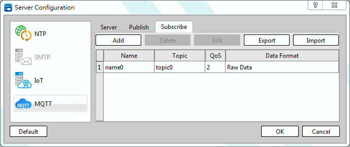
Figure 84 Topic setting of MQTT topic subscribe
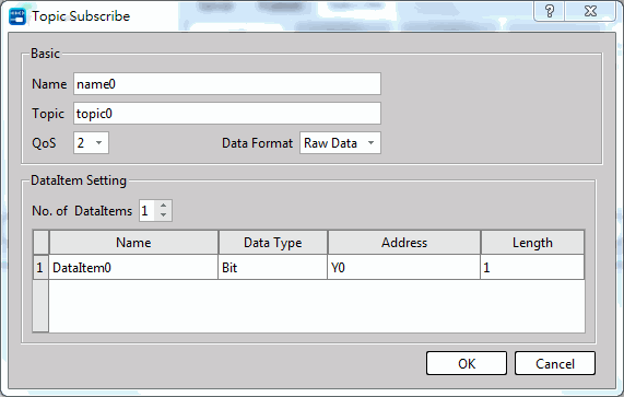
Figure 85 Topic Subscribe
|
Column |
Description |
||||||||
|
【Basic】 |
【Name】 Setting the topic name for making detailed description. 【Topic】 The topic used when MQTT is transmitting the message. (Notice: “#” and “+” are wildcard characters and they should not be used). 【QoS】 For setting the QoS (Quality of Service) for MQTT, and it comprises the following 3 classes:
【Data Format】 The message content of each individual subject is composed of the address values of the data item, as per the format below: 【Raw Data】 01 2a 03 b8 1e e5 3f 6c 6f 76 65 【JSON】 { "d": { "DataItem0": [true, true], "DataItem1": [810, 793, 688], "DataItem2": [1.789, 3.51], "DataItem3": ["love"] }, "error": [], "ts": "2019-06-18T10:55:41.491" } 【Custom】 User-defined Text using %1, %2, … variables to incorporate register or relays. Note:
|
||||||||
|
【Set figure data item】 |
【Number of figure data item】 Set the number of figure data item required for such subject. Described below is the detailed setting of figure data item. 【Name】 The name of figure data item cannot be left as blank and the name of each item must be unique and exclusive. The user shall be allowed to input the item name directly. 【Type of figure data】 It comes with 【bit】, 【16-bit BCD number】, 【16-bit positive integer】, 【32-bit BCD number】, 【32-bit integer】, 【32-bit positive integer】, 【32-bit floating point number】 and 【Ascii (U.S.)】 for option. 【Address】 Based on the type of figure data, the user will be allowed to set the address for each individual figure data item. 【Length】 If the type of figure data is configured in 16-bit, it will occupy one byte and 32-bit will occupy two bytes. In case of Ascii-String, it allows the user to determine the number of bytes that will be occupied by the figure data item. Each individual byte can accommodate 2 bits. |
Table 25 Setting Properties of Topic Subscription Edit Window
11-4Status Register
The system provides the MQTT status register R35679 for users to check the MQTT connection status.
|
R35679 Status Code |
Description |
|
0 |
Connected |
|
1 |
Version not support |
|
2 |
Descriptor Mismatch |
|
3 |
Access Denied |
|
4 |
Wrong account & password |
|
5 |
Authentication failed |
|
256 |
Connection Closed |
|
257 |
Connection Timeout |
|
258 |
Memory Allocation Failed |
|
259 |
Incompatible Custom Format |
11-4-5 Used Tools
This chapter describes the MQTT related tools:
Using external Broker
In 【Host (IP or domain name)】 of 【Server】 setup page, input the IP address or the domain name of the external Broker.
Example: Using the publicly tested Broker on Mosquitto (https://test.mosquitto.org/)
- Host: test.mosquitto.org
- Port: 1883
Install the Broker
It allows the user to install the Broker.
Example: Using Mosquitto (http://mosquitto.org/download/), and it is a public and free resource. For detailed installation and using method, please visit its website.
11-4-6 Client application
To monitor the data transmitted by MQTT, it will be required to use the MQTT client program provided by the third party for connecting to the selected Broker and then you may subscribe the topic published by HMI in order to receive the updated data. Currently, a lot of free MQTT client programs are available on the network for download.
Example: MQTT.fx (https://mqttfx.jensd.de/index.php/download)
11-5 Modbus TCP Communication Protocols
Modbus TCP Slave Station
The scope of Modbus slave station address conversion can be planned by the designer in "Modbus
Address Allocation" through software, please refer to Section 10-4-2.
Modbus TCP Master Station
Use the Modbus network communication connection command to communicate, please refer to
Section 11-5-1.
11-5-1 Convenient command for Modbus network communication connection
|
FUN152 NCR |
Convenient command for Modbus network (Master station) communication connection |
FUN152 NCR |
|||||||||||||||||||||||||||||||||||||||||||||||||||||||||||||
|
Symbol |
|||||||||||||||||||||||||||||||||||||||||||||||||||||||||||||||
|
|
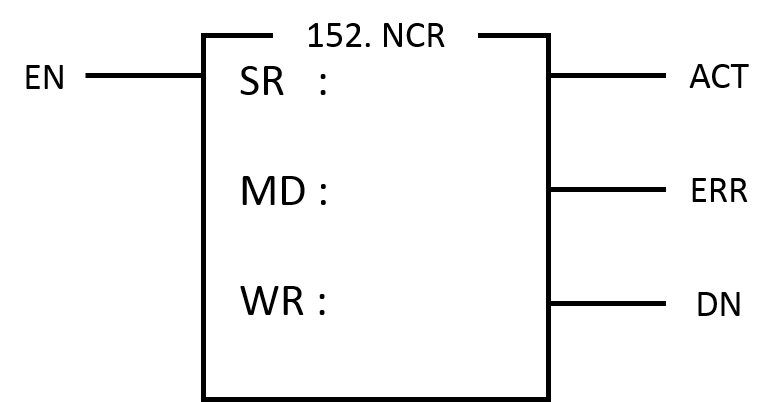
SR: Starting register address in the table MD: WR: Working Register |
||||||||||||||||||||||||||||||||||||||||||||||||||||||||||||||
|
|||||||||||||||||||||||||||||||||||||||||||||||||||||||||||||||
|
Description |
|||||||||||||||||||||||||||||||||||||||||||||||||||||||||||||||
|
|||||||||||||||||||||||||||||||||||||||||||||||||||||||||||||||
|
FUN152 NCR |
Convenient command for Modbus network (Master station) communication connection |
FUN152 NCR |
||||||||||||||||||||||||||||||||||||||||||||||||||||
|
Description of FUN152 command operand SR
|
||||||||||||||||||||||||||||||||||||||||||||||||||||||
|
FUN152 NCR |
Convenient command for Modbus network (Master station) communication connection |
FUN152 NCR |
||||||||||||||||||||||||||||||||||||||||||||
|
Description of FUN152 command operand SR
When it is Modbus TCP active communication (specified station number), it must be adjusted as follows:
|
||||||||||||||||||||||||||||||||||||||||||||||
|
FUN152 NCR |
Convenient command for Modbus network (Master station) communication connection |
FUN152 NCR |
|||||||||||||||||||||||||||||||||
|
The data type, code and initial number of FATEK master station.
Note: The data type of Master and Slave must be the same. In other words, if Master Station is Y/M/S, then the Slave Station must be coded as”0/1”. If the Master Station is R/D, then the Slave Station must be coded as “3/4”; and vice versa. |
|||||||||||||||||||||||||||||||||||
|
FUN152 NCR |
Convenient command for Modbus network (Master station) communication connection |
FUN152 NCR |
|||||||||||||||||
|
Description of FUN152 command operand WR High Byte Low Byte
Function Code: Low Byte valid; =0, read slave PLC system status =1, read slave PLC data =2, write data to slave PLC Result code: 0, communication success. 2, data length error (=0 or out of upper limit.) 3, command code error (=0, or <3) 4, data type error (refer data types code) |
|||||||||||||||||||
|
FUN152 NCR |
Convenient command for Modbus network (Master station) communication connection |
FUN152 NCR |
|
|
5: Data number is incorrect (see data starting number). 6: Master and slave data type are not the same. (e.g., Master Station is Y/M/S and Slave Station is coded as “4”). 8: Illegal communication table is used. A: Slave Station remains inactive (Time-out error) B: Communication is abnormal. (Receiving incorrect data or incorrect message is replied by Slave Station). C: Connect error |
|||
|
Example |
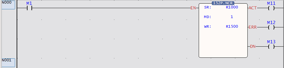
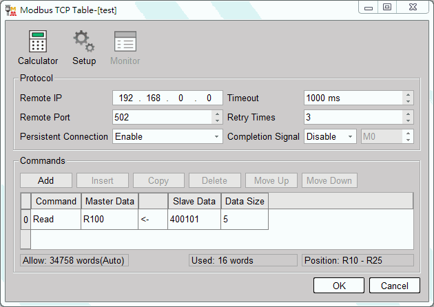
Slave Station 400101– 400105 (IP: 192.168.0.151) to Master Station R100–R104 addresses (IP: 192.168.0.150). |
||
|
Description of program example When the input control "EN" changes from 0 to 1, based on the settings in the Modbus TCP table, the remote IP Slave Station reads the register data and stores it in the PLC Master Station, and continuously completes the data transaction. For detailed setting steps, please see the description provided below 1. First, add the “Modbus Master” table in the original data list. 2. In Modbus Master table, define remote IP and Port as well as the address that will be read and written, including the Master Station and Slave Station data. 3. Edit Fun152 NCR command in Master Station Ladder. |
|||
|
FUN152 NCR |
Convenient command for Modbus network (Master station) communication connection |
FUN152 NCR |
|
|
Example |
|||
|
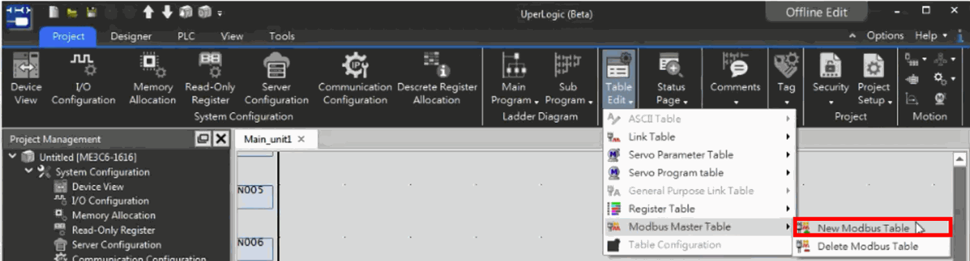
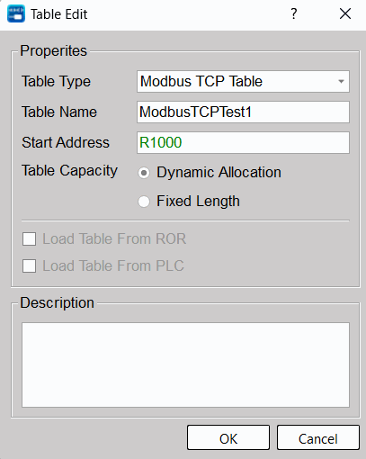
Edit communication table with UperLogic In Project window, click followings: Data List Modbus Master Table Press right key and then click “New Modbus Table”. The table type will be “Master TCP table”. You may also click “Table Edit” in “Project” tag, roll down for selecting “Modbus Master table” and then select “New Modbus Table”. The table can also be configured as “Modbus TCP table” type.。
|
|||
|
FUN152 NCR |
Convenient command for Modbus network (Master station) communication connection |
FUN152 NCR |
|
|
Example |
|||
|
Figure 87 Editing Modbus Master Table
|
|||
|
FUN152 NCR |
Convenient command for Modbus network (Master station) communication connection |
FUN152 NCR |
|
|
Example |
|||
|
Figure 88 Modbus Master Table
|
|||
11-6 iMonitor Remote Monitoring
FATEK IoT provides a new iMonitor remote monitoring HMI and PLC solution, as long as the device can be connected to the Internet, users can easily obtain the data on the device, and can monitor and access multiple device systems at the same time, and receive the system alarm information and data collection function in a real time for remote debugging and troubleshooting. In terms of communication security, there is also a professional security encryption mechanism to help customers check, so as to effectively protect the operation and access equipment data, and avoid the use of malicious people. Above, users do not need to make any network settings.
For detailed usage, please refer to the FATEK IoT cloud service user manual linked below:
https://www.fatek.com/zh-tw/download.php?act=list&cid=16
11-6-1 HWID
Every FATEK product that supports iMonitor has a unique device code called HWID. You can view 【PLC Status】 in the project, as shown in the figure below, and you can also view the current iMonitor connection status in this window. The same information can also be obtained in server-related settings. In order to facilitate the user to register the device correctly in the cloud background, click the function icon behind the HWID to quickly copy the HWID text content.
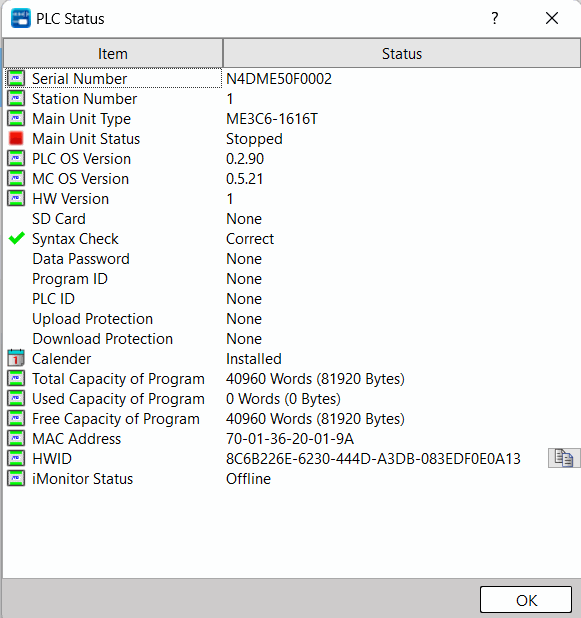
Figure 81 Status of PLC
11-6-2 Server Setting
For the iMonitor function, click 【IoT】 in the 【Server Configuration】 window in the 【Project】 on the left to enter its setting page. The 【Server】 tab can be used to view and configure iMonitor, as shown in the figure below:
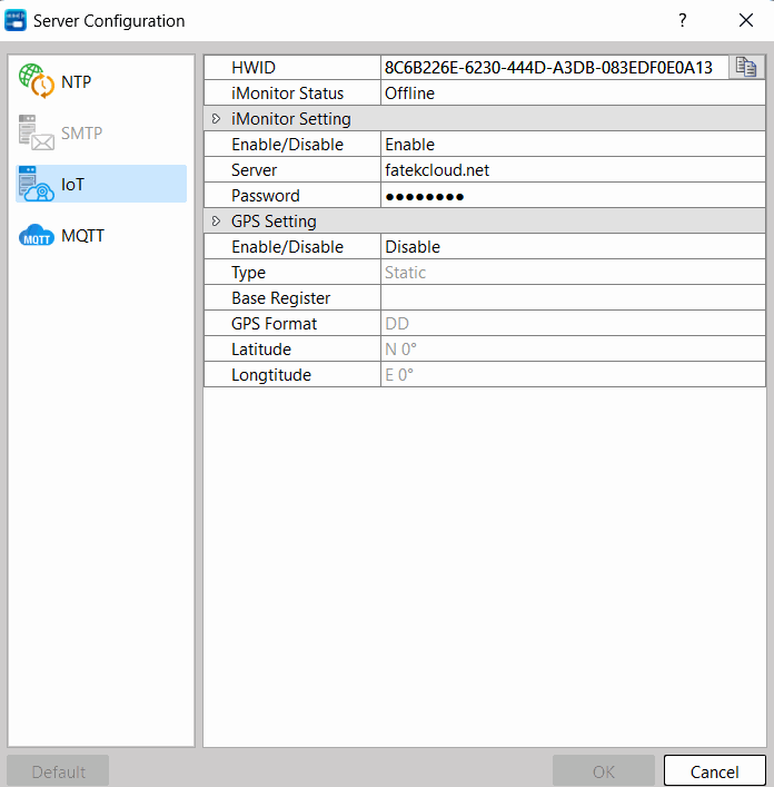
Figure 81 iMonitor setting window
11-6-3 Status Register
In addition to knowing the iMonitor connection information through the software interface, the relevant detailed information can also be obtained in the status register R35483.
|
R35483 Status Code |
Description |
|
0 |
Offline |
|
1 |
Online |
|
2 |
In connection |
|
Other |
Error code |
11-7 Fatek Binary’s open protocol explains the communication protocol
Please reference Fatek Binary communication user manual.
Tip: press ← → to switch chapters, Ctrl+K to search