|
⚠Danger |
|
This section describes the program creating procedure that will be required for editing the Ladder Diagram.
6-1 Main Program and Sub-Program Unit Management
The editing window is divided into Master Program Field and Sub-program Field. It presents orderly organized program architecture for users to carry out the editing and the checking more easily. Both units are operated in the same way. Described below is the operation procedure of each program unit:
6-1-1 Creating new program unit
During the planning, the programs can be categorized for editing in order to present orderly organized program architecture. With such kind of program unit adding function, a well-defined architecture will be presented when planning the program.
You may click [Project] → [Ladder Diagram] → [Main Program] → [Right mouse button] → [Main Program Add] in project management toolbar, or you may select [Main Program Add] from the scroll-down menu in function toolbar icon.
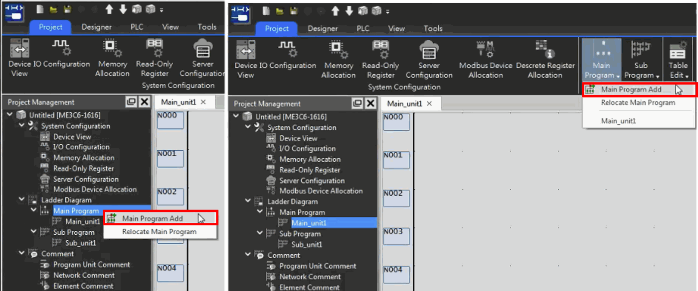
Fig. 71: Add Main Program Unit
6-1-2 Deleting program unit
If the created program unit is no longer required, you may delete it with the program unit deleting function. In this case, you may move the cursor to the unit tag and then click the right mouse button → [Delete] and then such program unit will be deleted.
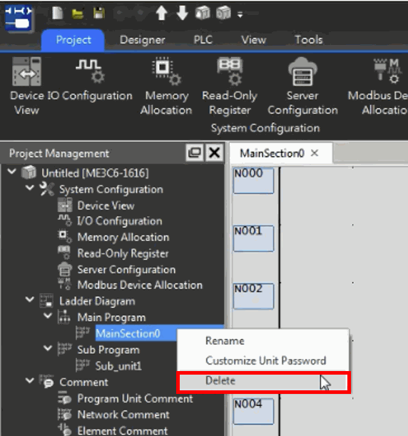
Fig. 72: Deleting program unit
6-1-3 Program unit relocating sequence
You may click [Project] → [Ladder Diagram] → [Main Program] → [Right mouse button] → [Relocate Main Program] in project management toolbar, or you may select [Relocate Main Program] from the scroll-down menu in the toolbar icon.
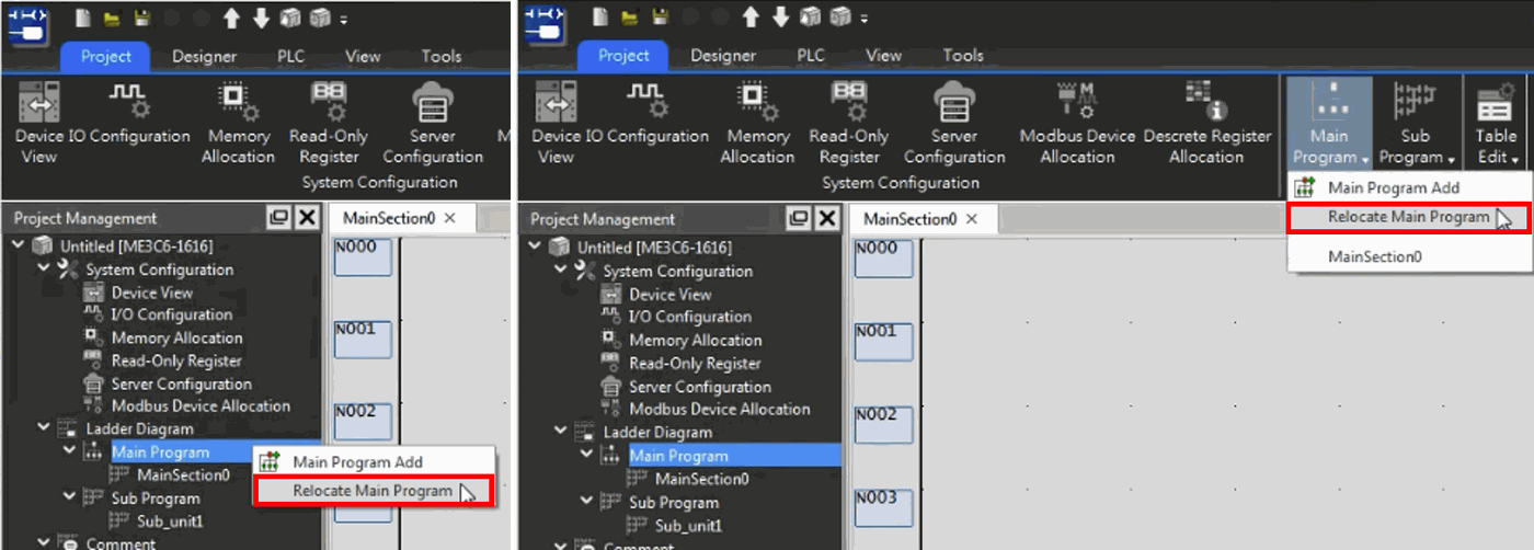
Fig. 73: Relocating Master Program Unit
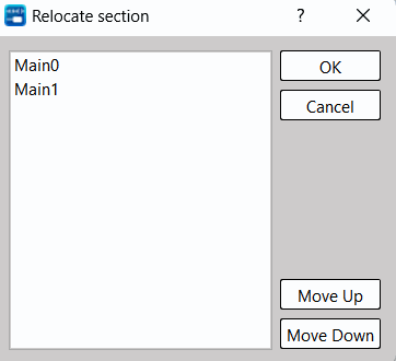
Fig. 74: Relocating Master Program Unit_2
Press [OK], and you may change the array of the program unit in the project window.
The [Relocate Main Program] of Sub-program can be adjusted in the same way as the Main Program. In this case, simply select the function from the Sub-program.
6-1-4 Changing program unit name
After creating the program unit name, you may change the program unit name. Click [Test Example]→ [Ladder Diagram] → [Main Program] → [Main Section] in project management window and then press the right mouse button → [Rename]:
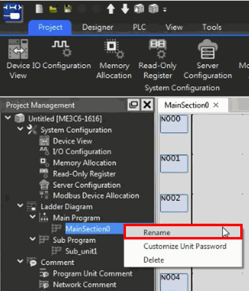
Fig. 75: Changing program unit name
6-1-5 Inputting program unit comment
If several program units are to be processed, it will be required to create a comment for the respective program unit for the convenience of checking and changing later on.
Inputting comment operation method in dedicated Comment Field
Click [Project] → [Comment] → “Program section” → “Double-click left mouse button” in function toolbar, or you may click toolbar icon and then the [Program Unit Comment] input field will appear.
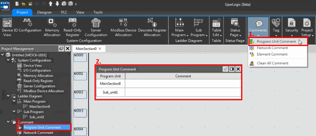
Fig. 76: Program unit comment
Input the comment text. Press [OK] and the comment will be displayed at the topmost side of such Ladder Diagram.
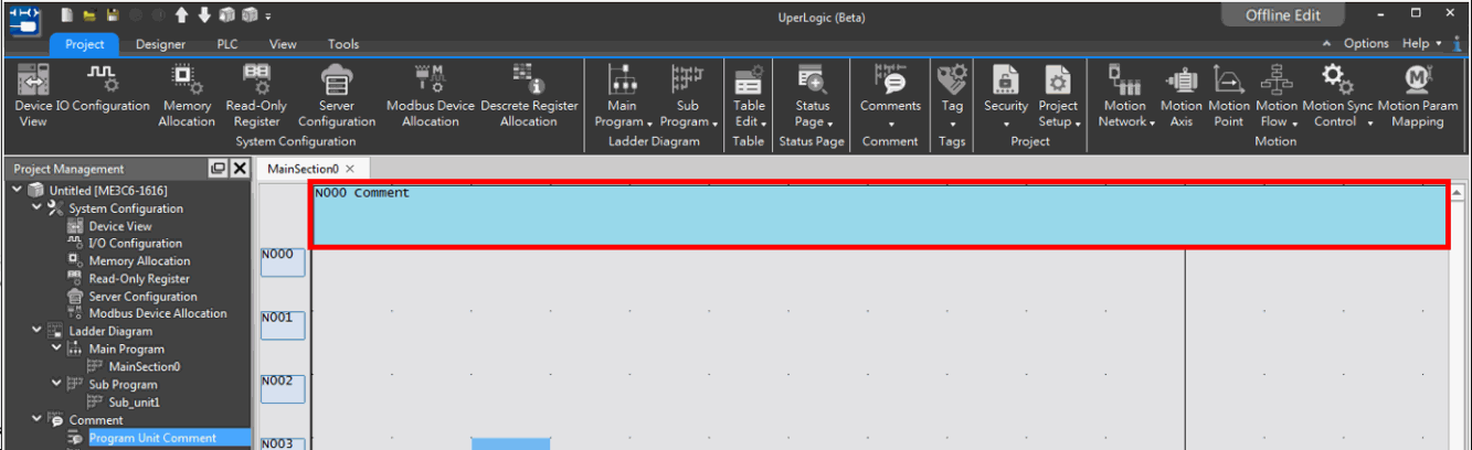
Fig. 77: Displaying comment at topmost side of Ladder Diagram
Operation method for inputting comment by selecting Single Program Unit
In the Ladder Diagram program field, click the right mouse button and the function menu will appear for selecting the desired [Network Comment] function:
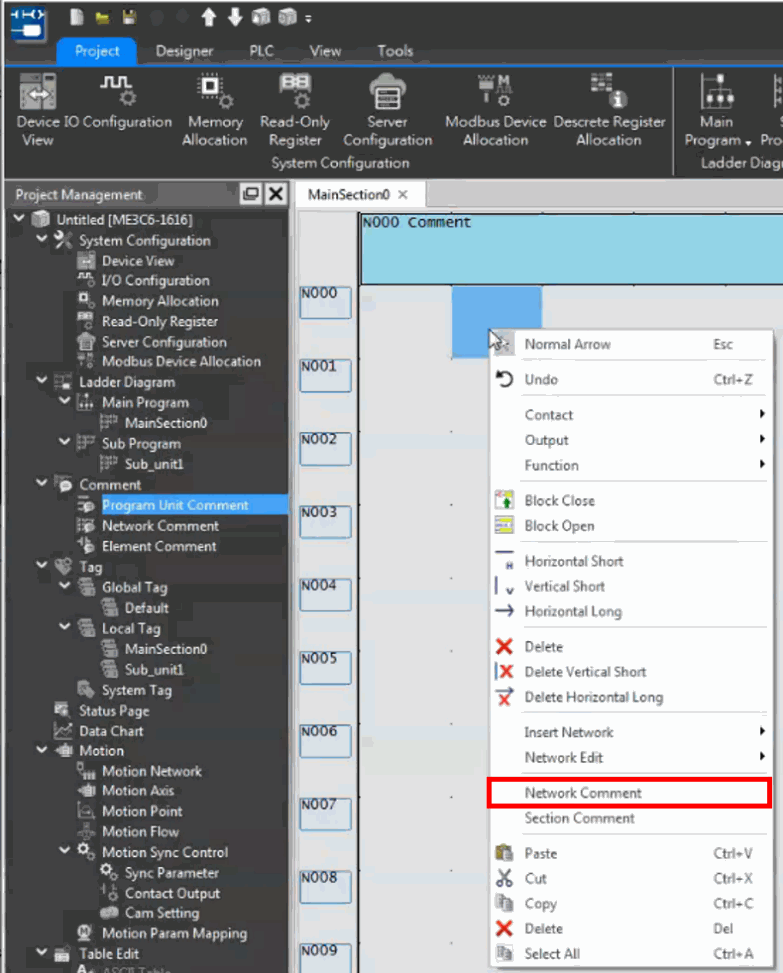
Fig. 78: Adding unit network comment
You may click [Project] → [Comment] → [Network Comment] in function toolbar and the program comment input field representing the respective unit will appear.
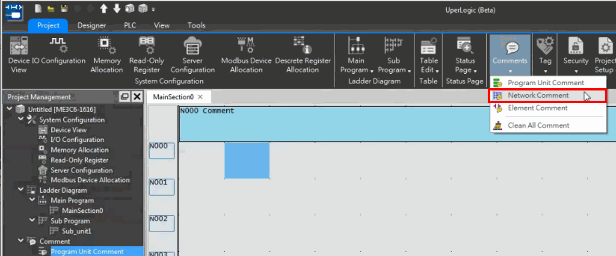
Fig. 79: Network Comment
Press [OK] to complete the inputting of network comment.
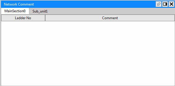
Fig. 80: Inputting network comment
Press [OK] and the comment will be displayed at upper side of the program.
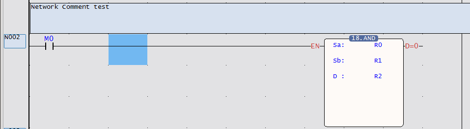
Fig. 81: Displaying comment at upper side of the program
6-2 Ladder Diagram (LD)
The most essential part of such application program is the compilation of the Ladder Diagram related program. For this purpose, it also provides the well-organized window in order to display relevant messages. Described below is its operation method:
6-2-1 Display elements
Window operation
It provides a number of window-based ladder program pictures for showing the programs being created for different sections at the same time for users to execute the compare, copy and edit functions.
- Creating multi-ladder window
Each project comprises Master Program Section and Sub-program Section in which, each section will be allowed for adding the desired program tab, as per the figure below. By clicking “Switch page” in the “Tab,” it allows the user to switch between the program section of each page.
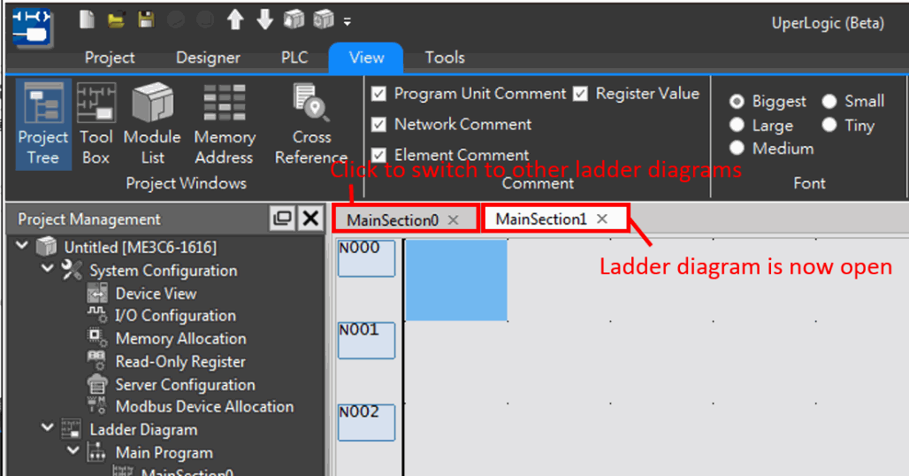
Fig. 82: Creating multi-ladder window
- Arraying of ladder window
- Arraying of cascade display:
Click [Window] → [Cascade]
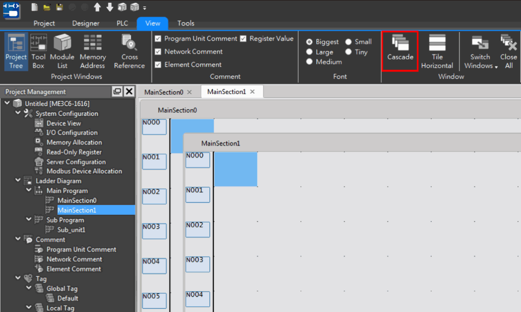
Fig. 83: Cascade window
- Arraying of tile horizontal display:
Click [Window] → [Tile Horizontal]
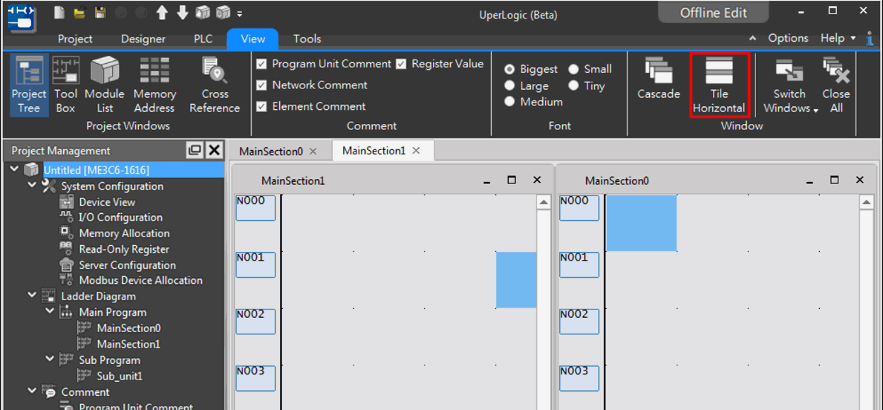
Fig. 84: Tile Horizontal display
6-2-2 Component operation
Click [Designer] → [Ladder Diagram] in function toolbar, and the component items from A Contact to vertical line will be displayed. Indicated in the figure below is the arraying method of the respective contact component in the company panel, as below:
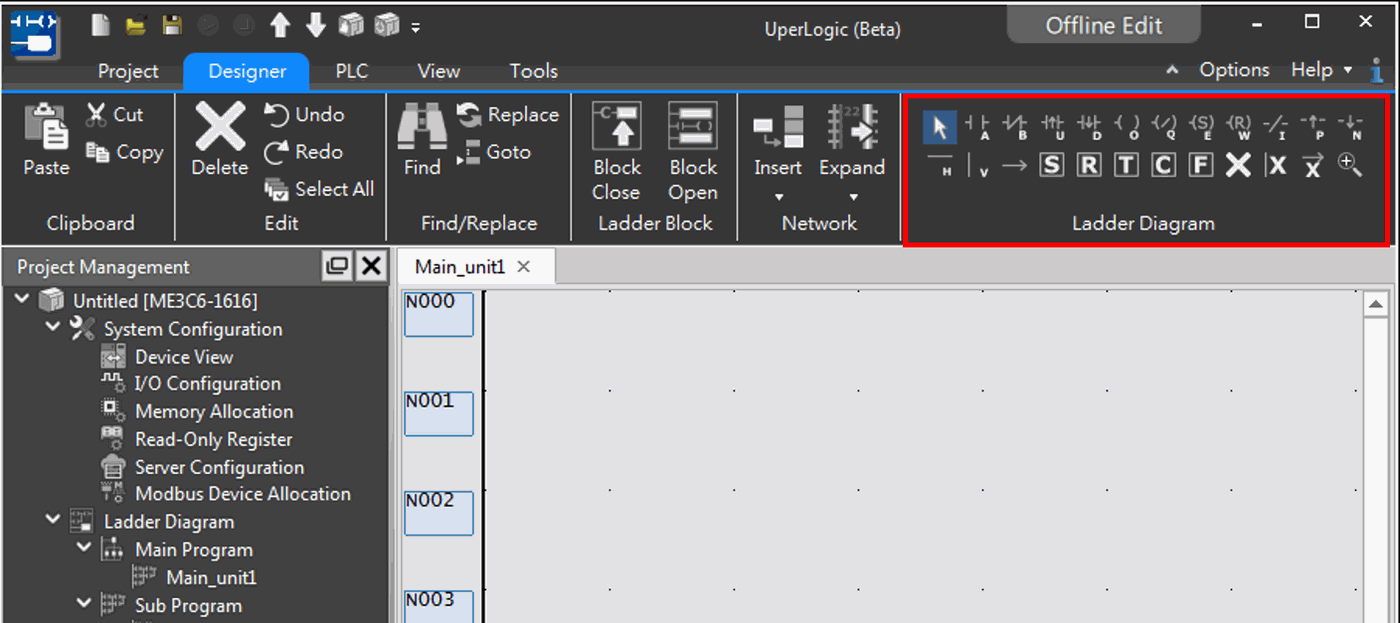
Fig. 85: Ladder Diagram component operation
Select the contact component that will be imported. Drag such component to Ladder Diagram program section and it will be displayed. Described below is the operation procedure:
Input contact component
Click [Designer] → [Component Panel] → [A Contact]  in function toolbar.
You may also move the cursor to the Ladder Diagram program section and then click the right mouse button and the Pop-up Menu will appear as the figure below. After that, select [Contact] → [A Contact]:
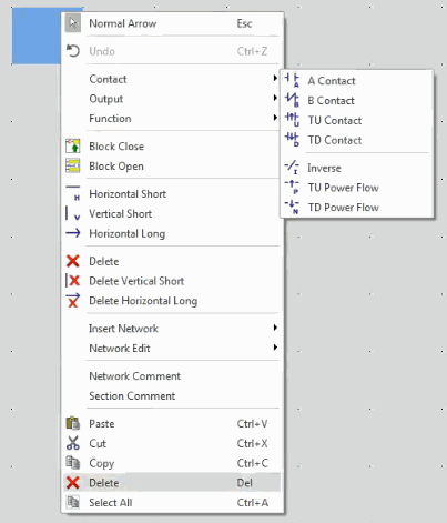
Fig. 86: Inputting contact component
Click the desired input position in the Ladder Diagram program section, and the [Element Edit] box will appear:
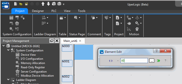
Fig. 87: Inputting component number
After inputting “X0”, press “ENTER” key and the picture will be displayed as below:
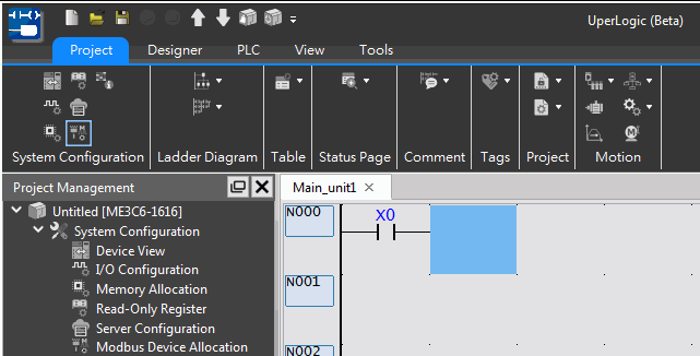
Fig. 88: Complete component inputting
Next, move the cursor to the input position in the Ladder Diagram program field. After that, click the left mouse button once and then input “AX0” or “X0A” with keyboard and the figure above will appear.
In the meantime, press “Shift” + “A” keys to show the webpage where A Contact component will be displayed in program section only without inputting the component number, as per the figure below:
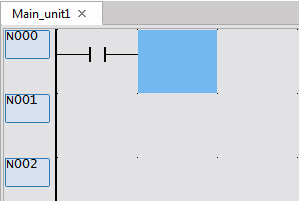
Fig. 89: Page without inputting component number
Changing the type or the number of contact component
To change the type of the contact component being entered, select the contact type to be changed; for example, select B Contact from the component panel, and then click the left button on the contact component to be modified in the ladder diagram program section, and the input number box of the B contact element will appear.
To change the component number, move the cursor to the component to be changed in the program section and then enter the new number or press “SPACE” key to show the edit window. After that, input the new number as per the figure below.
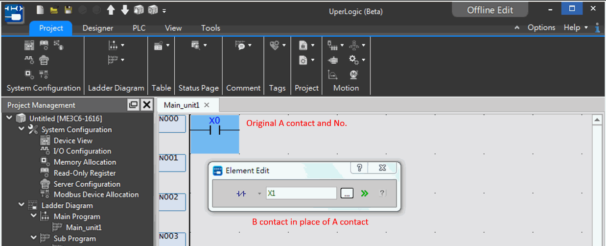
Fig. 90: Component number changing method
You may also key the number in the “Element Edit” box at B Contact, such as “X1”. After that, the “X0” of the original A Contact will be revised as “X1” of B Contact.
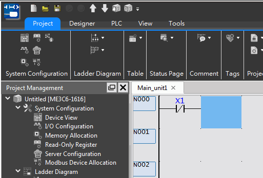
Fig. 91: Component number changing result
Deleting contact component
In component panel, you may select deletion icon  or move the cursor to the Ladder Diagram program section. Next press the right mouse button to display the Pop-up Menu where you will be allowed to select the [Delete] function. At this time, the cursor serves as the deleting function; or you may click [X1] of B Contact component and then press “Delete” key on the keyboard and “X1” will be deleted.
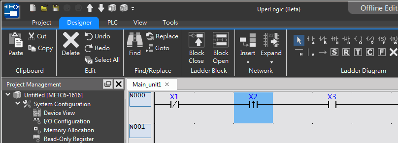
Fig. 92: Selecting the component to be deleted
Press “Delete” key on the keyboard, it will be deleted directly. 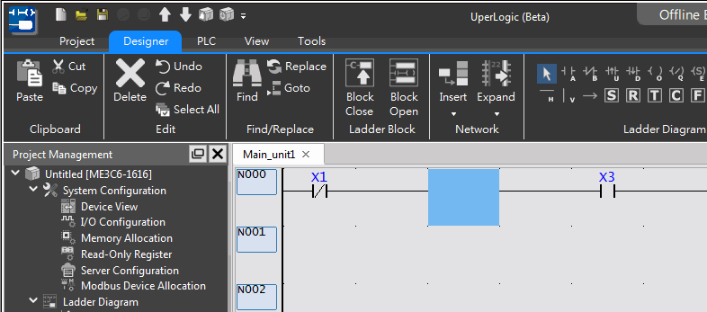
Fig. 93: Deleting component by clicking Delete
6-2-3 Operating by instructions
The UperLogic also provides convenient function instruction set. You may select the required instruction by clicking [Check] → [ToolBox] → [Set/Reset] → [Timer/Counter] → [Function Instruction] in function toolbar and drag the module to the configuration position by clicking the left mouse button. In the meantime, you may also click the component panel icon  which can be used as the function instruction option.
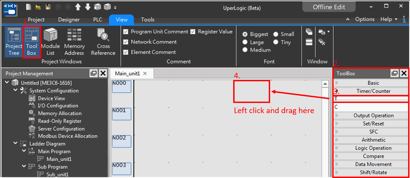
Fig. 94: Dragging Function instruction
After releasing the left mouse button, the function instruction will appear. After inputting the parameter setting, press [OK] to complete the configuration.
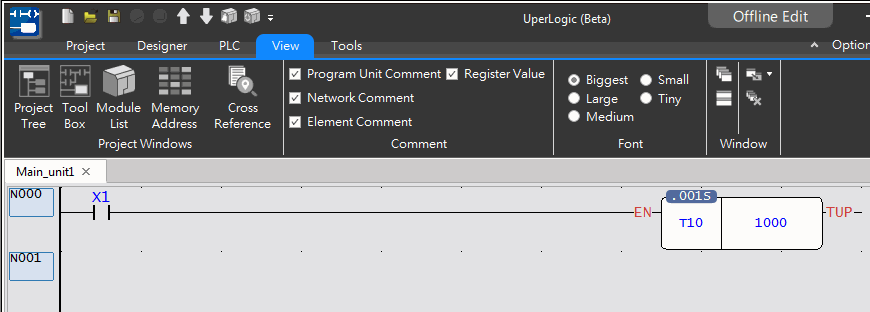
Fig. 95: Completing component dragging
Input Function instruction
If users want to use different function instructions, for example, when setting a fixed time timer, it is necessary to control the timing start, when the timing ends, and how much value the timing accumulates, etc., the operation steps can refer to the following instructions:
To set up a fixed-time Timer between X1 contact and Y0 output, you may input the Function instruction to carry out the setting:
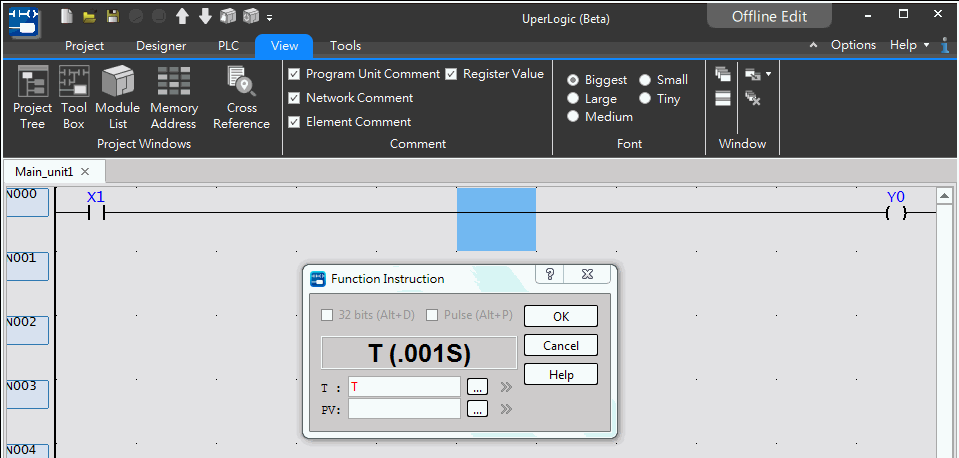
Fig. 96: Setting by inputting Function instruction
You may click [Designer] → [Ladder Diagram] → select timer function icon from component panel in function toolbar. At this time, the cursor is serving as the Timer. In the Ladder Diagram program section, click the space between X1 and Y0 and the “Timer” Function instruction setting dialog box will appear.
In the Ladder Diagram program section, you may also click the space between X1 and Y0 and then press “Shift” + “T” quick keys and the “Timer” Function instruction setting dialog box will appear:
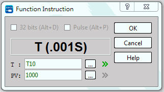
Fig. 97: “Timer” Function instruction setting dialog box
Key “T10” in “T” column and key “1000” in “PV” section to complete the fixed-time setting for the Timer:
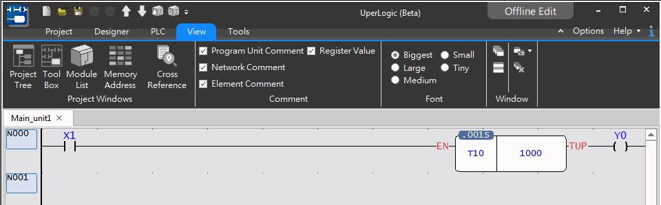
Fig. 98: Completing the fixed-time setting for Timer
Deleting functional component
You can select the delete icon in the component panel, or click the right button in the ladder diagram program section to display the Pop-up menu to select the [Delete] function, and the cursor represents the delete function; or directly click the function component, and then press the keyboard “Delete” key, you can also delete it directly
6-2-4 Network operation
In the Ladder Diagram program section, the network is an essential element that is designed with a variety of operation methods. Described below is the network operation method in the program section.
Copying single network
Point the cursor at the network to be copied. For example, network “N009” per the figure below:

Fig. 99: Replicating single network
Press the right mouse button to show the Pop-up Menu and then select [Copy] or press “Ctrl” + “C” quick key and then execute the copy instruction. Next, press the right mouse button to show the menu for selecting [Paste]; or press “Ctrl” + “V” quick key to execute the paste command. In this way, it allows the user to complete the single network copying:

Fig. 100: Complete the copying of single network
Copying multiple networks
To copy the connected networks coded in N001 to N003, the user may use the mouse to scroll the selected N001 to N003 or press “Shift” key and then click Network N001 to N003, as per the figure below:
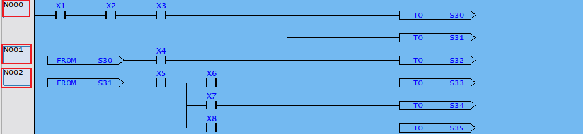
Fig. 101: Copying multiple networks
Execute the copying and pasting actions to complete the copying of networks that are connected with each other. To copy the non-connected networks such as N001, N003 and N005, highlights Network N001 with mouse, press “Ctrl” simultaneously and then highlights N003 and N005 to achieve the following result:
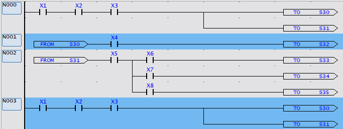
Fig. 102: Completing the copying of multiple networks
Execute the copying and pasting steps to complete the non-connected network copying.
Copying the network between different projects
First, open the UperLogic application program and then open Project-1 file. Likewise, open the UperLogic application program again and then open Project-2 file. In this way, you will be allowed to open two units of UperLogic application program windows. In Project-1, highlight Network N001 and press the right mouse button to show the Pop-up Menu and then select [Copy] or press “Ctrl” + “C” quick keys to copy the desired network. Next, move the cursor to the pasting position in Project-2 and then press the right mouse button to show Pop-up Menu. Next, select [Paste] or press “Ctrl” + “V” quick key to paste the network. In this way, it allows the user to complete the copying of network between different projects.
Deleting network
Highlight the Network Number to be deleted and then click [Designer] → [Delete] in function toolbar, or press “Delete” quick key and it will be deleted directly.
Editing network lines and rows
In the Ladder Diagram, the program section is composed of multiple Network Numbers. Through the lines and rows of the Network Number, an orderly configured program is presented that will be easier for maintenance. Further, other functions are also designed for the network lines and rows to achieve more convenient and quicker program compilation. Described below is the operation method of these functions:
Expand network to 22 lines
If multiple contacts are created that will be insufficient for the original 11 lines in the network, it can be expanded to 22 lines. By doing so, move the cursor to the network where 11 lines will be expanded to 22 lines and then click [Designer] → [Network] → [Expand to 22 lines] in function toolbar; or you may press the right mouse button to show Pop-up Menu and then click [Edit Network line/row] → [Expand to 22 lines].
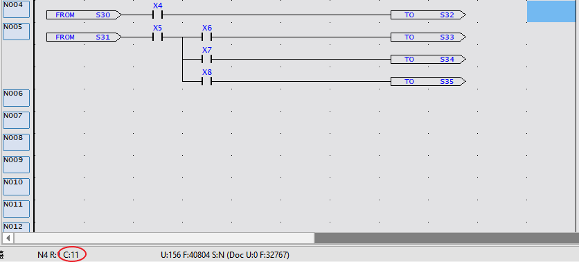
Fig. 103: Before expanding to 22 lines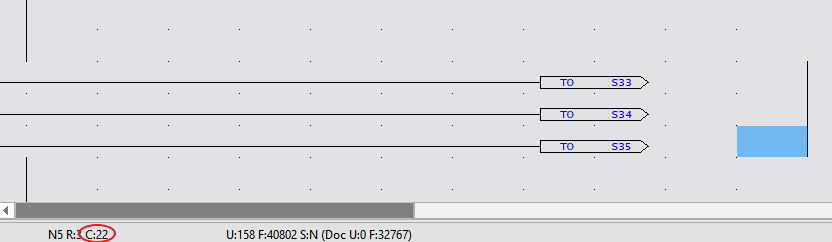
Fig. 104: After expanding to 22 lines
Compressing network to 11 lines
Move the cursor to the network where 22 lines will be compressed to 11 lines and then click [Designer] → [Network] → [Compress to 11 lines] in function toolbar; or you may press the right mouse button to show Pop-up Menu and then click [Edit Network line/row] → [Compress to 11 lines].
Vertical expanding
To expand the vertical distance between the upper and lower lines of X1 and X3, execute per the figure below: 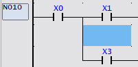
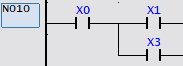
Fig. 105: Expanding vertical distance
Click X3 with cursor:
Click [Designer] → [Expand Network] → [Vertical Expand]; or press the right mouse button to show Pop-up Menu and then click [Edit Network line/row] → [Vertical Expand] to complete the vertical expanding.
Vertical compressing
To compress the vertical distance between the upper and lower lines of X1 and X3, execute per the figure below:
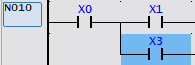
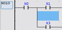
Fig. 106: Compressing vertical distance
Then the cursor clicks the blank row to be compressed between X1 and X3:
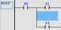
Fig. 107: Clicking the empty rows to be compressed
Click [Designer] → [Expand Network] → [Vertical Compress]; or press the right mouse button to show Pop-up Menu and then click [Edit Network line/row] → [Vertical Compress] to complete the vertical compressing.
Horizontal expanding
To expand the distance between X0 and X3:


Fig. 108: Expanding horizontal distance
Click [Edit] → [Expand Network] → [Horizontal Expand] in function toolbar; or press the right mouse button to show Pop-up Menu and then click [Edit Network line/row] → [Horizontal Expand] to complete the horizontal expanding.
Horizontal compressing
To compress the distance between X0 and X3:


Fig. 109: Compressing horizontal distance
Click [Edit] → [Expand Network] → [Horizontal Compress] in function toolbar; or press the right mouse button to show Pop-up Menu and then click [Edit Network line/row] → [Horizontal Compress] to complete the horizontal compressing.
Inserting empty network
To insert an empty network in the upper side of Network N012, execute the following procedure:
In the Ladder Diagram program section, move the cursor to any component contact of N012 and then press the right mouse button to show Pop-up Menu. Next, click [Insert Empty Network] → [Upper Insert]; or you may press the right mouse button of Network N012 to show Pop-up Menu and then click [Insert Empty Network] → [Upper Insert]; or click [Designer → [Insert Network] → [Upper Insert]; or press “Shift” + “Insert” quick keys and then Network N012 will become an empty network. In the meantime, the content of original Network N012 will change to Network N013.


Fig. 110: Inserting empty network
Searching network
To search Network N001 of the intended program unit, click [Designer] → [Go To]; or press “Ctrl” + “G” quick keys to show the following window:
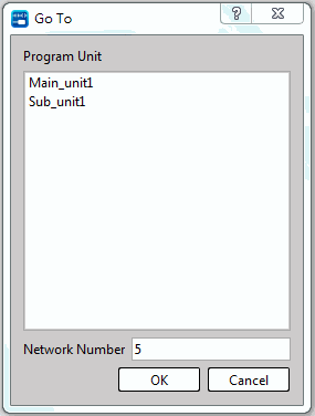
Fig. 111: Searching network
Taking the searching of Network N005 in [Main_unit1] for example:
In [Program Unit List], highlights [Main_Unit-1] and then enter “5” in [Network Number] column to represent N005. Next, press [OK] button and the cursor will move to the Network Number position to be searched.
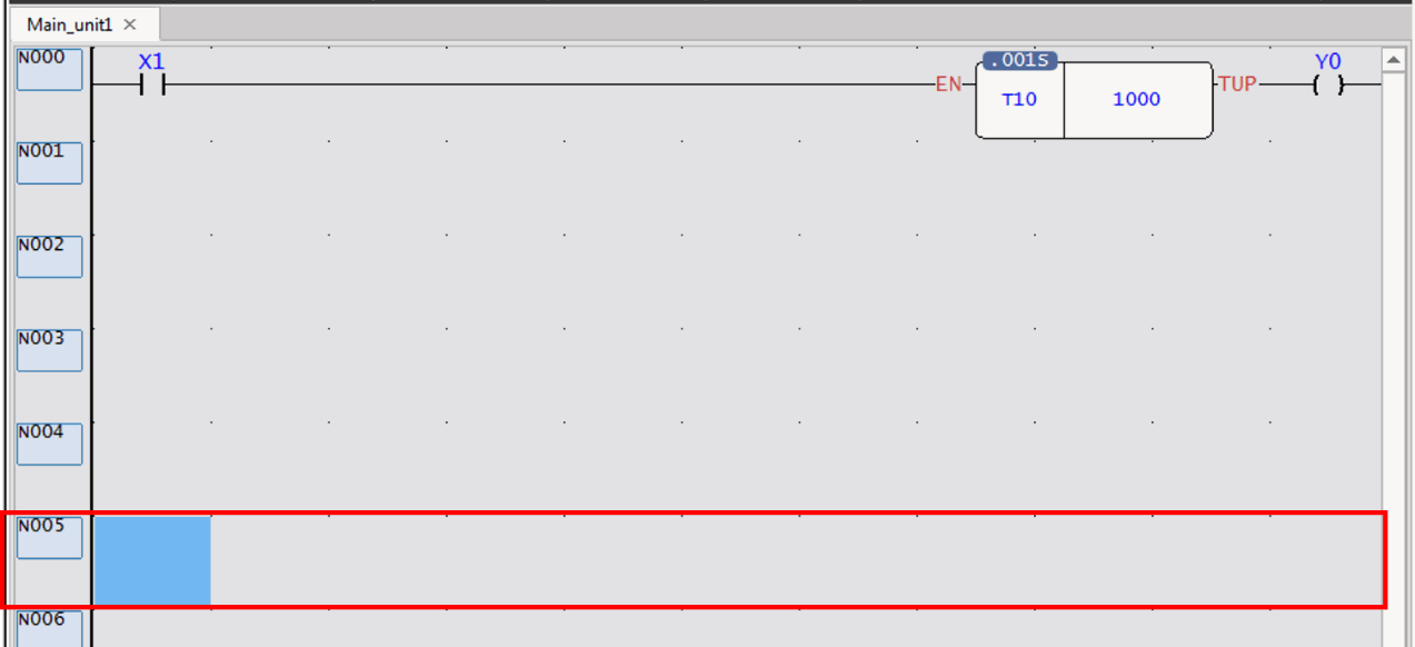
Fig. 112: Moving to the Network Number position to be searched
6-2-5 Editing comment
To input the network comment for Network N012, move the cursor to N12 or any component and then press the right mouse button to show Pop-up Menu. Next, click [Network Comment] and the network comment input section will appear:
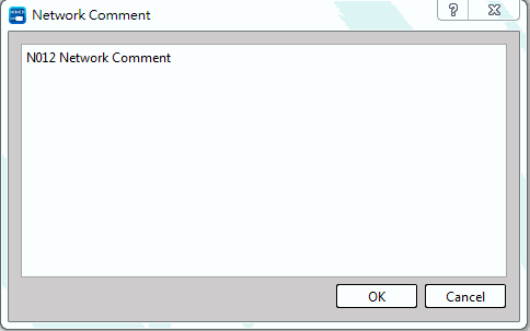
Fig. 113: Network comment input section
Input “N012 Network Comment.” Press [OK] button and you will see that the keyed comment is displayed in the previous line of the existing Network N012:

Fig. 114: Displaying comment in previous line of Network Number
In the meantime, you may double click [Project] → [Comment] → [Network Comment]; or in project window, double clicking → [Comment Description] → [Network Comment] to show all of the Network Numbers. Find out N012 by scrolling down the menu and then double clicking on the empty comment section and the network comment input empty section will appear:
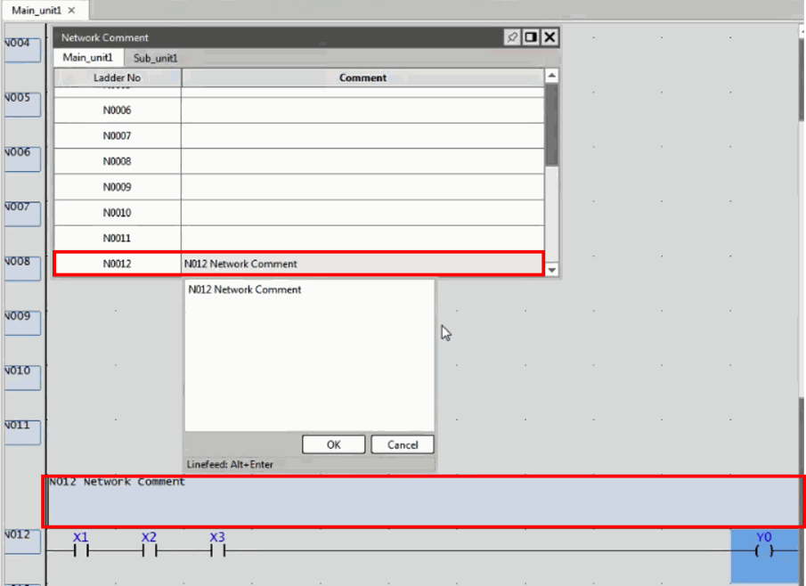
Fig. 115: Adding network comment
Input “N012 Network Comment” and then press [OK] button to complete the network comment inputting.
6-3 Structured Text (ST)
In addition to the most basic editing of ladder diagram programs, UperLogic also provides a structured document programming language (Structured Text), whose syntax is similar to Pascal. Through this syntax, it is convenient to perform complex logic and calculations that are more difficult to edit than ladder diagrams. Commonly used programs and circuits can also be edited through Function Block (FB) is created for repeated use. For more detailed information, please refer to the ST manual. The operating method is introduced as follows:
6-3-1 Display Composition
Window Operation
Provides a multi-window ladder program page, which can display programs in different sections at the same time for comparison, copying and editing.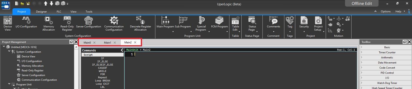
Fig. 116: List of programs in use
6-3-2 Commands Operation
[Commands] on the left side of the ST window will provide users with corresponding commands, which are divided into three categories: Script, Toolbox and FCM:
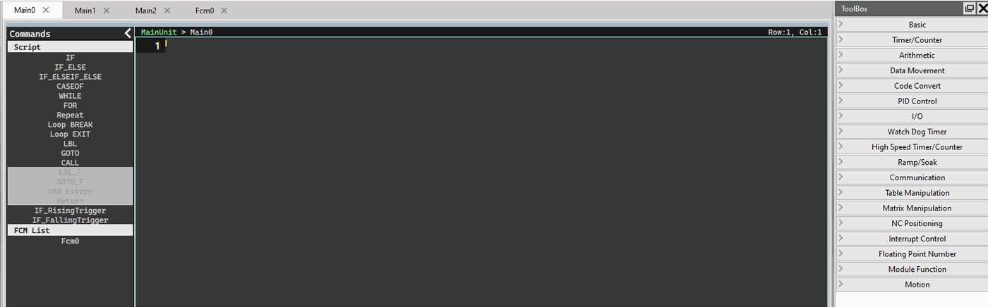
Fig. 117: ST commands operation
Double-click the command you want to use or enter it directly on the screen to use it. The following is the operation instruction:
Script:
Users can write programs through the instructions here. For example, after double-clicking the IF, the screen will display the corresponding specifications, and use ( ) to prompt the user to fill in the information here. If the user already understands, you can also directly enter the corresponding command.
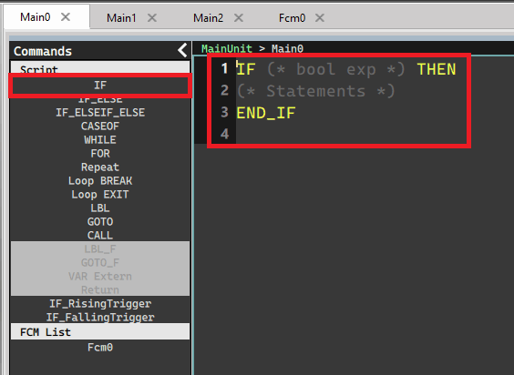
Fig. 118: Syntax hints comments
ToolBox:
Users can edit the project through the written program, and the function here will be similar to the Ladder command. The method of use is the same as that of ToolBox. For example, after double-clicking Timer, the corresponding specification will be displayed on the screen, and ( ) will be used to prompt the user to fill in the information here. If the user already understands it, he can also directly enter the corresponding command.
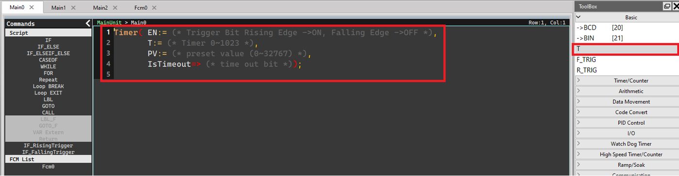
Fig. 119: Function hint comments
FB:
Users can use the function blocks written in the function block program to edit the project.
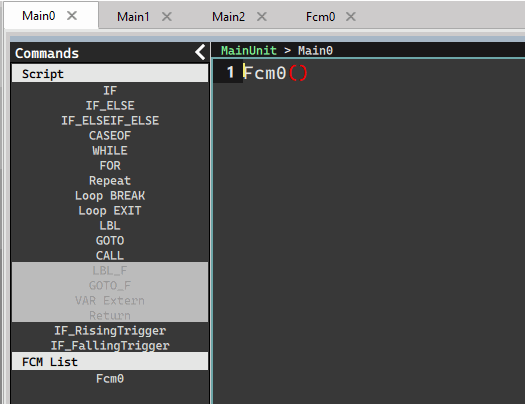
Fig. 120: Using Function Block
For the interface operation of the function block, please refer to Chapter 6-7.
6-4 Step Ladder Instruction Description
6-4-1 Instruction-based operation
The main purpose is to achieve higher program readability, easier maintainability and updating, as well as more reliable software quality. Aiming at the sequential control of mechanical action process, the software is designed for combining the widely accepted Ladder Diagram language under the support of step-based execution command. To operate, click [Designer] → [Ladder Diagram] → [Function Lookup] or press “F” quick key; or in Ladder Diagram program field, press the right mouse button to show Pop-up Menu and then click [Function Lookup] → [Function Lookup]. In the Ladder Diagram program section, click the position where step instruction will be conveyed and all types of function instructions will appear. Under type item, select [SFC instruction] and the right-side Function Name will show the following four step instructions, i.e., “STP,” “FROM,” “TO” and “STPEND,” as per the figure below:
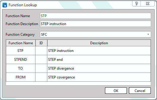
Fig. 121: SFC instructions
For its operation instructions, please refer to Chapter 8 of the M-PLC instruction application manual:
6-5 Syntax Check
After inputting the ladder program, the system will be allowed for executing the syntax check to help you find out program errors. To execute, click [PLC] → [Syntax check] in function toolbar to show the error statistic list resulting from the syntax check:
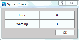
Fig. 122: Syntax check
The system will list all errors under the program section. In the error section, double clicking any item in error section and the program section will show the error component block, as per the figure below:
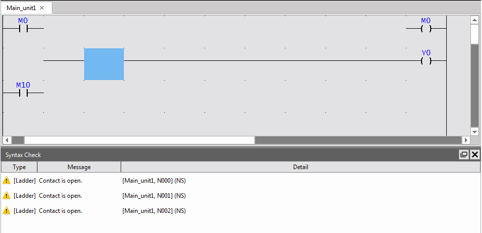
Fig. 123: Error displaying resulting from syntax check
6-6 Interrupt Program
UperLogic classifies related interrupt programs and motion control subroutines here, which is convenient for users to use and design. For example, to add an interrupt program, you only need to add and select the interrupt type, instead of defining the interrupt program through the command Label 65 and the end of RTI like Winproladder. In addition to the ladder LD language, programmers can also write special program logic through ST. Each special type of program is unique and cannot be repeated.
6-6-1 Types of Interrupt Program
|
Interrupt Source |
Priority |
Interrupt Label |
Condition |
Note |
|
Hardware Time Tick |
3 |
STM0I |
Interval from 1ms~9ms |
Tick unit 1ms |
|
3 |
STM1I |
Interval from 1ms~9ms |
||
|
3 |
STM2I |
Interval from 1ms~9ms |
||
|
3 |
STM3I |
Interval from 1ms~9ms |
||
|
3 |
LTM0I |
Interval from 10ms~60000ms |
Tick unit 10ms |
|
|
3 |
LTM1I |
Interval from 10ms~60000ms |
||
|
3 |
LTM2I |
Interval from 10ms~60000ms |
||
|
3 |
LTM3I |
Interval from 10ms~60000ms |
||
|
HSC |
2 |
HSC0I |
Interval from HSC0 to (CV=PV) |
|
|
2 |
HSC1I |
Interval from HSC1 to (CV=PV) |
||
|
2 |
HSC2I |
Interval from HSC2 to (CV=PV) |
||
|
2 |
HSC3I |
Interval from HSC3 to (CV=PV) |
||
|
2 |
HSC4I |
Interval from HSC4 to (CV=PV) |
||
|
2 |
HSC5I |
Interval from HSC5 to (CV=PV) |
||
|
2 |
HSC6I |
Interval from HSC6 to (CV=PV) |
||
|
2 |
HSC7I |
Interval from HSC7 to (CV=PV) |
||
|
HST |
1 |
HST0I |
Interval from HST0 to (CV=PV) |
Tick uint 100us |
|
1 |
HST1I |
Interval from HST1 to (CV=PV) |
||
|
1 |
HST2I |
Interval from HST2 to (CV=PV) |
||
|
1 |
HST3I |
Interval from HST3 to (CV=PV) |
||
|
Interrupt from External Hardware Input or Software High-Speed Timer |
X0+I (INT0+) |
X0 positive edge trigger |
The software high speed counter HSC0~HSC7 can be assigned as the trigger source of any interrupt X0~X15. Therefore, the interrupt priority of the software high speed counter depends on the priority of X0~X15. |
|
|
X0−I (INT0-) |
X0 negative edge trigger |
|||
|
X1+I (INT1+) |
X1 positive edge trigger |
|||
|
X1−I (INT1-) |
X1 negative edge trigger |
|||
|
X2+I (INT2+) |
X2 positive edge trigger |
|||
|
X2−I (INT2-) |
X2 negative edge trigger |
|||
|
X3+I (INT3+) |
X3 positive edge trigger |
|||
|
X3−I (INT3-) |
X3 negative edge trigger |
|||
|
X4+I (INT4+) |
X4 positive edge trigger |
|||
|
X4−I (INT4-) |
X4 negative edge trigger |
|||
|
X5+I (INT5+) |
X5 positive edge trigger |
|||
|
X5−I (INT5-) |
X5 negative edge trigger |
|||
|
X6+I (INT6+) |
X6 positive edge trigger |
|||
|
X6−I (INT6-) |
X6 negative edge trigger |
|||
|
X7+I (INT7+) |
X7 positive edge trigger |
|||
|
X7−I (INT7-) |
X7 negative edge trigger |
|||
|
Interrupt from External Hardware Input or Software High-Speed Timer (MA Series) |
X8+I (INT8+) |
X8 positive edge trigger |
The software high speed counter HSC0~HSC7 can be assigned as the trigger source of any interrupt X0~X15. Therefore, the interrupt priority of the software high speed counter depends on the priority of X0~X15. |
|
|
X8−I (INT8-) |
X8 negative edge trigger |
|||
|
X9+I (INT9+) |
X9 positive edge trigger |
|||
|
X9−I (INT9-) |
X9 negative edge trigger |
|||
|
X10+I (INT10+) |
X10 positive edge trigger |
|||
|
X10−I (INT10-) |
X10 negative edge trigger |
|||
|
X11+I (INT11+) |
X11 positive edge trigger |
|||
|
X11−I (INT11-) |
X11 negative edge trigger |
|||
|
X12+I (INT12+) |
X12 positive edge trigger |
|||
|
X12−I (INT12-) |
X12 negative edge trigger |
|||
|
X13+I (INT13+) |
X13 positive edge trigger |
|||
|
X13−I (INT13-) |
X13 negative edge trigger |
|||
|
X14+I (INT14+) |
X14 positive edge trigger |
|||
|
X14−I (INT14-) |
X14 negative edge trigger |
|||
|
X15+I (INT15+) |
X15 positive edge trigger |
|||
|
X15−I (INT15-) |
X15 negative edge trigger |
|||
|
MQ model DI Plug-in (MQ Series) |
X16+I |
X16 positive edge trigger |
||
|
X16-I |
X16 negative edge trigger |
|||
|
X17+I |
X17 positive edge trigger |
|||
|
X17-I |
X17 negative edge trigger |
|||
|
X18+I |
X18 positive edge trigger |
|||
|
X18-I |
X18 negative edge trigger |
|||
|
X19+I |
X19 positive edge trigge |
|||
|
X19-I |
X19 negative edge trigger |
|||
|
X20+I |
X20 positive edge trigger |
|||
|
X20-I |
X20 negative edge trigger |
|||
|
X21+I |
X21 positive edge trigger |
|||
|
X21-I |
X21 negative edge trigger |
|||
|
X22+I |
X22 positive edge trigger |
|||
|
X22-I |
X22 negative edge trigger |
|||
|
X23+I |
X23 positive edge trigger |
|||
|
X23-I |
X23 negative edge trigger |
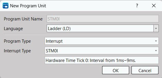
Fig. 124: Select interrupt program type
6-6-2 Types of motion program
|
Motion Source |
Priority |
Motion Label |
Condition |
Note |
|
Motion Control |
1 |
MSR |
Motion Synchronous Routine |
Interrupt every 1 ms cycle. |
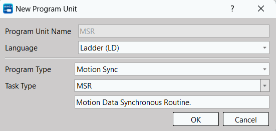
Fig. 125: Select motion program type
MSR can be regarded as the continuous PLC program flow after the action of the continuation of the motion process. It is used as the planning of synchronous motion parameters to avoid the running time difference between the PLC program and the motion process. Designers can synchronize motion parameters in the MSR program to output to PLC registers or output Y contacts in real time, ensuring that the output of motion control will not be affected by the existing PLC program logic. For more details, please refer to the chapter on motion control.
6-6-3 Add special program
Click [Project] → [Program Unit] → [Special Program] → [Add Special Program] with the mouse; or right-click [Add Special Program] in the project management window [Special Program] to create a new special program:
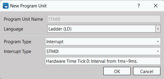
Fig. 126: Add special program unit
Program Unit Name:
Will be automatically generated by the system, and will have the same name as the interrupt or motion control type.
Language:
Users can choose whether this special program unit is edited using ladder diagram or ST programming language.
Interrupt Type:
Usera can choose the type of the interrupt program, and each interrupt type can only create one program unit, which cannot be created repeatedly.
6-6-4 Adjust Interrupt Program
Click [Project] → [Program Unit] → [Interrupt Program] → [Adjust Interrupt Program]; or right-click [Adjust Interrupt Program] in the project management window [Interrupt Program] to adjust the interrupt program order of sorting:
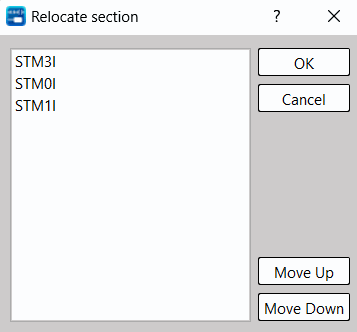
Fig. 127: Adjusting Interrupt Program
6-6-5 Call Interrupt Program
The calling of the interrupt is not by using software instructions, but by sending an interrupt signal to the CPU through the hardware circuit, and the CPU recognizes the name of the interrupt and automatically jumps into the interrupt subroutine and marks it with the interrupt name.
6-7 Function Module Program
In PLC programming, to allow users to easily reuse code, simplify and speed up programming, avoid errors and repetitive debugging, and even establish commonly used libraries for programmers to facilitate reuse in different projects, M PLC provides the FCM function module program. This allows users to easily implement Function and Function Block features to modularize PLC programs. For detailed usage, please refer to M PLC Function / Function BlocK User Manual.
6-7-1 Add Function Module Program
Click [Project] → [Program Unit] → [Function Module Program] → [Add FCM Program] with the mouse; or right-click [Add FCM Program] in the project management window [Function Module Program], you can add new function module program:
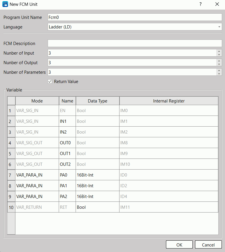
Fig. 128: Add Function Module Program
Program Unit Name:
Users can define the name of the desired program unit at the time of creation, and this name will be used when calling this function block program when other program units are programmed.
Language:
Users can choose whether to use the ladder diagram or ST programming language to edit the interrupt program unit.
Function Module Description:
Users can define the required program unit descriptions by themselves.
Input Numbers:
Users can set the quantity to be input, the minimum is 1 and the maximum is 8. The first group of input names is fixed as EN, and the remaining 7 groups of input names can be edited by the user.
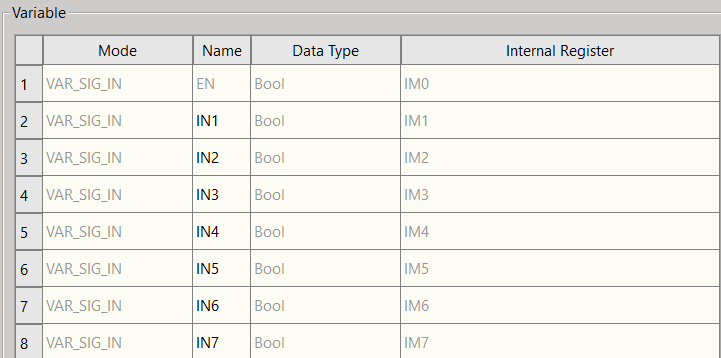
Fig. 129: FCM input variables
Output Numbers:
Usera can set the quantity to be output, the minimum is 0 and the maximum is 8. Users can edit the name of the output by themselves.
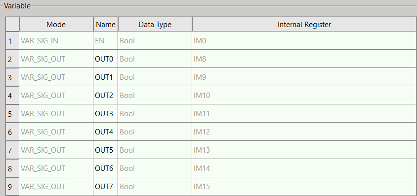
Fig. 130: FCM output variables
Parameter Numbers:
The user can set the number of parameters required by the function module, the minimum is 0, and the maximum is 12. Users can define the mode, name and data type of parameters by themselves, which will be explained one by one below:
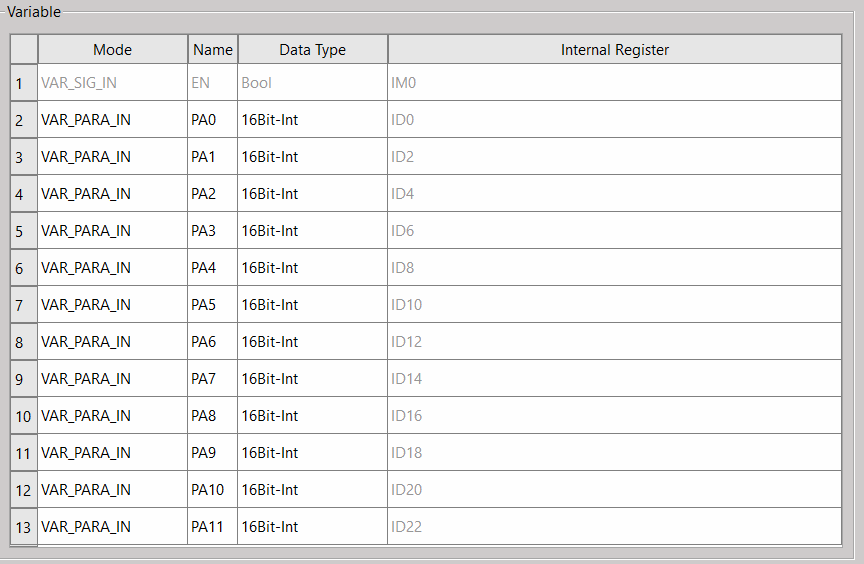
Fig. 131: INOUT parameters of function block
- Mode
Users can choose the mode of this parameter as input (IN), output (OUT), or output-input (INOUT). When IN is selected, the value of the parameter before entering FCM will be inherited, and the change in FCM will be ignored after the function block is terminated.
When selecting OUT, the value of the parameter before entering the FCM will be ignored, and if the value is changed, it will be output to the designated register.
When INOUT is selected, it will have both the characteristics of IN and OUT, inherit the value of the parameter before entering FCM, and retain the changes in FCM.
- Name
Users can define the name of the parameter by themselves.
- Data Type
Users can select the data type of the parameter as 16Bit-Int, 16Bit-UInt, 32Bit-Int, 32Bit-UInt or Float.

Fig. 132: Data type
- Return Value
After checking, the return value and the specified register will be output. It is mainly used in ST language.
6-7-2 Adjust Function Module Program
Click the function bar [Project] → [Program Unit] → [FCM Program] → [Adjust FCM Program] with the mouse; or right click [Adjust FCM Program] in the project management window [FCM Program] to adjust the FCM program order of sorting:
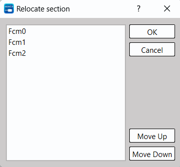
Fig. 133: Adjusting FCM Program
6-7-3 Import and Export Function Module Program
- Import:
Click the function bar [Project] → [Program Unit] → [FCM Program] → [Import Program] with the mouse; or right click [Import Program] in the project management window [FCM Program].
- Export:
Right click the program to be exported in project management window and select [Export Program].
Tip: press ← → to switch chapters, Ctrl+K to search