|
⚠Danger |
|
This section describes the system related parameters that will be required for setting up the content of I/O configuration, memory configuration and read-only Register.
5-1 I/O Configuration
I/O configuration provides configuration enablement and adjustment of high-speed counters, interrupts, outputs and inputs. Execute the function bar [Project] → [I/O Configuration], or click [Test Example] → [System Configuration] → [I/O Configuration] in the project management window: High-Speed Counter.
Different modules have different numbers of high-speed counters, HSC0~3 provide 6 counting modes:
- Single-phase independent up-counting high-speed counter U
- Single-phase independent up-counting high-speed counter U*2
- Single-phase relative up/down high-speed counter P/R
- Bidirectional correlation high-speed counter A/B
- Bidirectional correlation high-speed counter A/B*2
- Bidirectional correlation high-speed counter A/B*4
Some modules of HSC4~7 only provide A/B*4, and all modules provide software masking and clearing.
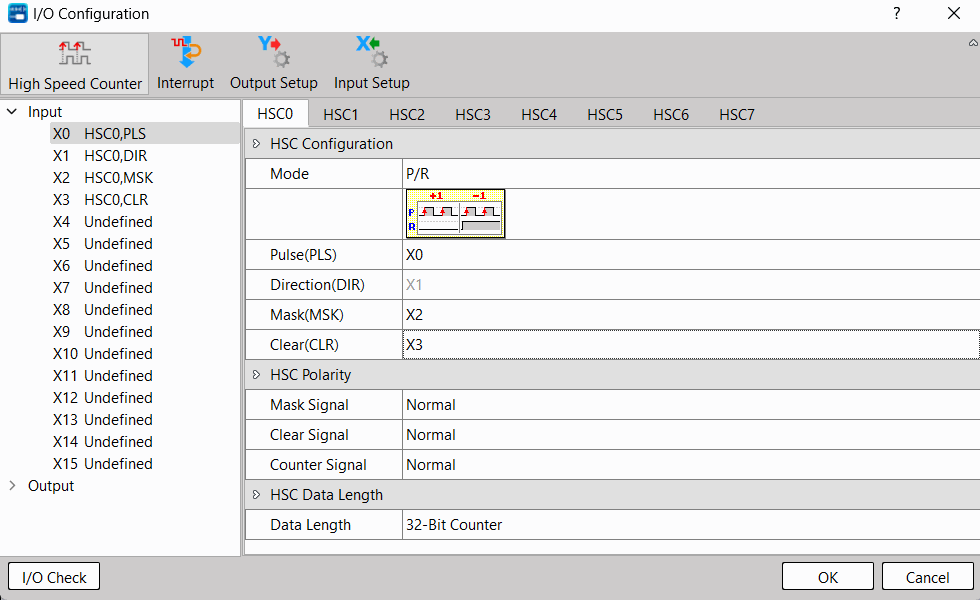
Fig. 54: High-Speed Counter
|
Item |
說明 |
|
|
HSC Configuration |
Up (UP)/Down (DN) A-Phase / B-Phase |
Sets the selection of the counting input of the high counter. |
|
Mask (MSK) |
Sets the selection for mask input. When the input signal is 1, the counter will be blocked and will not count, and the internal state will remain unchanged. When the signal returns to 0, the counter will work properly. |
|
|
Clear (CLR) |
Sets the selection to clear the input. When the input signal is 1, the current count value temporary register inside the counter will be cleared to 0 and cannot count. The counter will not start counting from 0 until the signal returns to 0. |
|
|
HSC Polarity |
Mask Signal |
Able to set the normal phase or negative phase of the mask input. |
|
Clear Signal |
Able to set the normal phase or negative phase of the clear input. |
|
|
Counter Signal |
The input signal can be set as normal counting or reverse counting. |
|
|
HSC Data Length |
Provides two modes “16-bit counter” and “32-bit counter” to choose from. For example: if the temporary register for HSC0 storing the count value is DR35280, if “32-bit counter” is selected, DR35280 will be used as the current count value register of the high-speed counter; if “16-bit counter” is selected, R35280 is still the current count value register of the high-speed counter. But R35281 will be used by the system as a 16-bit loop counter. |
|
The inputs of the counting mode are interdependent. Except “U”, which only has a single input, they must be used in pairs. For example, when “X4” is selected in the “A-Phase” field, “B-Phase” will automatically use “X5”. The input selections of “Mask” and “Clear” also need to be paired, but you can choose to use only “Mask” or “Clear”. In order to achieve optimal benefits, the input points are configured as shown in the table below:
|
Input Point |
||||||||
|
Up (UP) |
Pulse |
A-Phase |
Down (DN) |
Direction |
B-Phase |
Mask (MSK) |
Clear (CLR) |
|
|
HHSC0 |
X0 |
NA |
X1 |
X2, X4, X6, X8, X10, X12, X14 |
X3, X5, X7, X9, X11, X13, X15 |
|||
|
HHSC1 |
X2 |
X3 |
||||||
|
HHSC2 |
X4 |
X5 |
||||||
|
HHSC3 |
X6 |
X7 |
||||||
|
HHSC4 |
X8 |
X9 |
||||||
|
HHSC5 |
X10 |
X11 |
||||||
|
HHSC6 |
X12 |
X13 |
||||||
|
HHSC7 |
X14 |
X15 |
||||||
Table 15 Configuration of input points
5-1-2 Interrupt Signal Configuration
The interrupt means that the PLC will send an interrupt request to the CPU immediately when the demand for immediate response occurs during the normal sequential execution of the scan cycle. After the CPU receives the interrupt request, it immediately stops the scanning work being executed, and executes the “interrupt service routine” first. After the task is completed, return to the unfinished scanning task. This page is used to set the use and trigger conditions of the input interrupt.
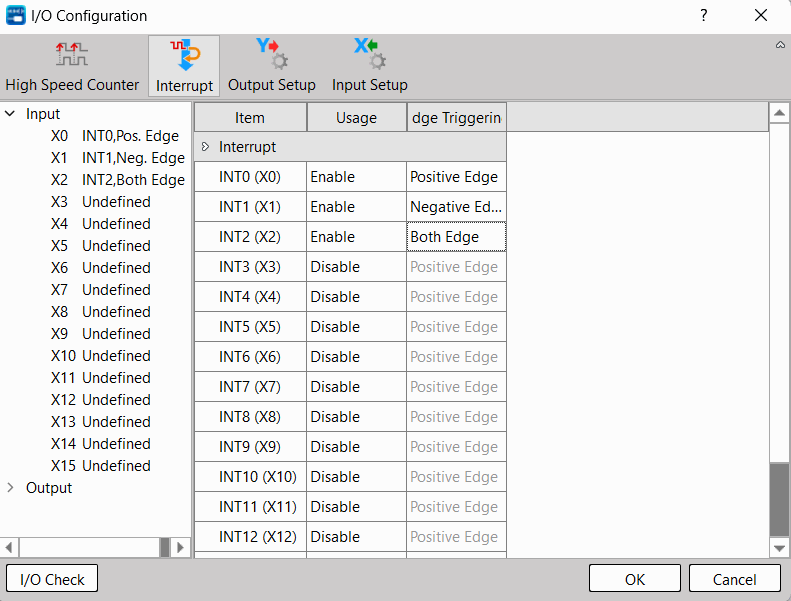
Fig. 55: Interrupt setting
|
Item |
Description |
|
Usage |
Set to enable or disable the interrupt function. |
|
Edge Trigger |
Set trigger conditions. [Positive Edge] Input from 0 to 1 [Negative Edge] Input from 1 to 0 [Positive and negative edges] trigger when input changes |
5-1-3 Output Signal Configuration
It is used to set the pulse form of output signal, output polarity and output power-off hold and other configurations.
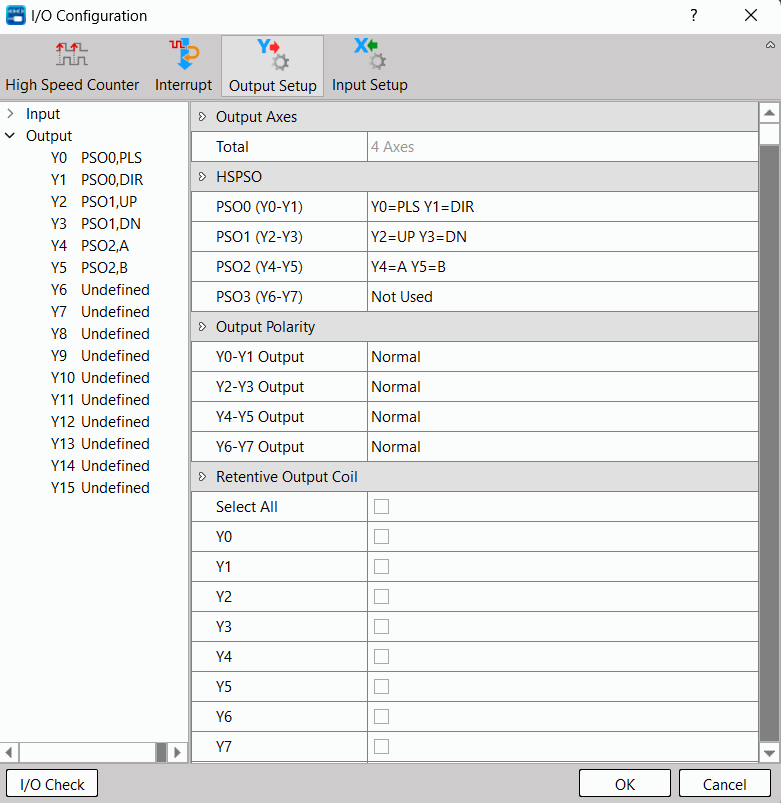
Fig. 56 Output Setting
|
Item |
Description |
|
High-Speed Pulse Output |
Set the output mode of high-speed pulse output. Divided into four modes
|
|
Output Polarity |
Select normal output or reversed output. |
|
Output Latched |
When checked, it means that when the power is turned on again, the output will keep the original output value. |
If not using the HSPSO function, the Y0–Y15 external output points of M-PLC will be corresponding to the status of Y0–Y15 output relays in the PLC. If the HSPSO is implemented, then the system will switch the Y0–Y15 external output points directly to the HSPSO output circuit in ASIC; therefore, it is irrelevant to Y0–Y15 relays in PLC.
Listed below are the signal details and the optional output modes of the output points at the respective axis of M-PLC. The “high-speed pulse output” can be set according to the method indicated in the table below:
|
Axis No. |
External Output Point |
Output Mode |
|||
|---|---|---|---|---|---|
|
PLS/DIR |
UP/DN |
A/B-Phase |
Single Point PLS |
||
|
PSO 0 |
Y0 Y1 |
Y0= PLS Y1= DIR |
Y0= UP Y1= DN |
Y0=A Y1=B |
Y0= PLS |
|
PSO 1 |
Y2 Y3 |
Y2= PLS Y3= DIR |
Y2= UP Y3= DN |
Y2=A Y3=B |
Y2= PLS |
|
PSO 2 |
Y4 Y5 |
Y4= PLS Y5= DIR |
Y4= UP Y5= DN |
Y4=A Y5=B |
Y4= PLS |
|
PSO 3 |
Y6 Y7 |
Y6= PLS Y7= DIR |
Y6= UP Y7= DN |
Y6=A Y7=B |
Y6= PLS |
|
PSO 4 |
Y8 Y9 |
Y8= PLS Y9= DIR |
Y8= UP Y9= DN |
Y8=A Y9=B |
Y8= PLS |
|
PSO 5 |
Y10 Y11 |
Y10= PLS Y11= DIR |
Y10= UP Y11= DN |
Y10=A Y11=B |
Y10= PLS |
|
PSO 6 |
Y12 Y13 |
Y12= PLS Y13= DIR |
Y12= UP Y13= DN |
Y12=A Y13=B |
Y12= PLS |
|
PSO 7 |
Y14 Y15 |
Y14= PLS Y15= DIR |
Y14= UP Y15= DN |
Y14=A Y15=B |
Y14= PLS |
Table 16: Output mode setting table
5-1-4 Input Signal Configuration
For many high-speed applications, in addition to using the interrupt input method to prevent signal omission, the input points included in the host can also be set as capture inputs to capture their fleeting signals. This page is used to set its captured input configuration.
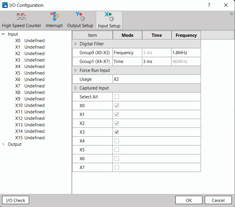
Fig. 57: Input Setting
|
Item |
Description |
|
Input Filter Value |
The filter settings are divided into 4 groups (X0~X3), (X4~X7), (X8~X11), (X12~X15), and the filter conditions can be set to time or frequency: 7 options such as 28KHz to 1.8MHz can be set when the frequency is used as the condition; 3 to 15 milliseconds can be set when the time is used as the condition. |
|
Forced Operation Input Point |
Set the point of forced operation input point. |
|
Captured Input Point |
Check to set it as the input point to be captured. |
5-2 Setting up the Number of Component Memory
When M-PLC leaves the factory, proper arrangements have been made in advance for the allocation of retentive and non-retentive coils or registers, timers, counters, and read-only registers. In most applications, the factory settings do not need to be changed, but in order to adapt to various special or complex applications, in addition to the factory settings, UperLogic also provides the function so that users can set them according to their needs.
Click [Project] →  [Memory Allocation] in function toolbar or double clicking → [System Configuration] → [Memory Allocation] in the project window and then the memory allocation setting window will appear:
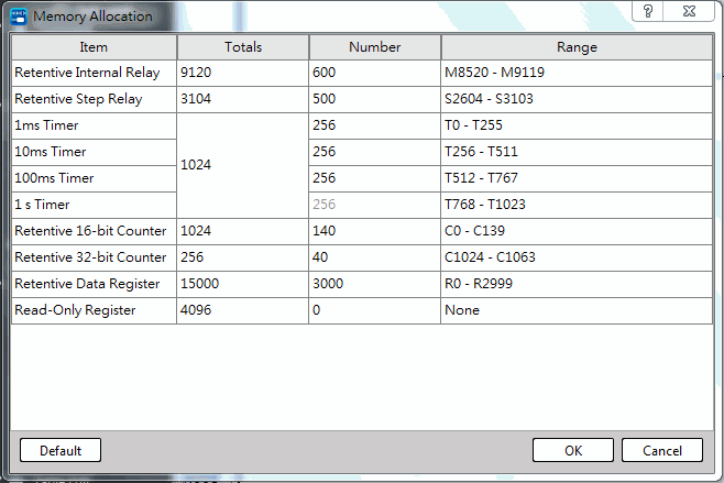
Fig. 58: Memory Allocation window
When restarting following the outage or switch PLC from STOP to RUN, the non-retentive relay or the Register will be cleared as “0”, but the retentive relay will maintain its original (before outage or under STOP status) status. Described below are relevant details:
|
Item |
Description |
|
Retentive Internal Relay |
[Total] Displays the total number that can be set as retentive type [Quantity] The quantity to be set as retentive type [Range] Displays the range after setting |
|
Retentive Step Relay |
[Total] Displays the total number that can be set as retentive type [Quantity] The quantity to be set as retentive type [Range] Displays the range after setting |
|
Time Base of Timer |
The timer is divided into four time bases of 1 ms, 10 ms, 100 ms and 1 s, and the four time bases share the total number. [Total] Displays the total number of timer [Quantity] The quantity to be set for each time base [Range] Displays the range of each time base setting |
|
Retentive 16-bit Counter |
[Total] Displays the total number that can be set as retentive type [Quantity] The quantity to be set as retentive type [Range] Displays the range after setting |
|
Retentive 32-bit Counter |
[Total] Displays the total number that can be set as retentive type [Quantity] The quantity to be set as retentive type [Range] Displays the range after setting |
|
Retentive Data Register |
[Total] Displays the total number that can be set as retentive type [Quantity] The quantity to be set as retentive type [Range] Displays the range after setting |
|
Read-Only Register |
[Total] Displays the total number that can be set as read-only register [Quantity] The quantity to be set as read-only register [Range] Displays the range after setting |
|
Retentive Input Register |
Set all output registers as retentive type or non-retentive type |
|
Default Value |
Restore to factory settings |
After the setting of the memory allocation window is completed, the system will display the [Discrete & Register Allocation] window to provide the user with an overview of the complete allocation status, as shown in the figure below:
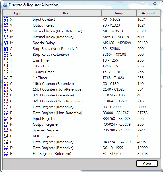
Fig. 59: Discrete and register allocation window
5-3 Setting up the Content of Read-Only Register
The configurable range of read-only registers is R43224~R47319 (4096 in total), and the range not planned as read-only registers can be used as general registers, which are retentive types. The content set as read-only registers will be stored in the project, so when the project is downloaded to the PLC, if there are read-only registers specified in the project, these read-only registers will be used when the PLC starts content as the initial value.
Click [Project] → [ROR Register] in function toolbar or double clicking [Test Example] → [System Configuration] → [ROR Register] in the project window. If the ROR range is not set, the following window will appear first to prompt the setting. When the setting is confirmed, it will automatically jump to the memory allocatoin window in Section 5.2 to provide the user with the set amount.
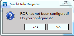
Fig. 60: Setting up read-only Register
The ROR window provides users with setting ROR data, comments and instructions, and can synchronize the Register value and ROR value.
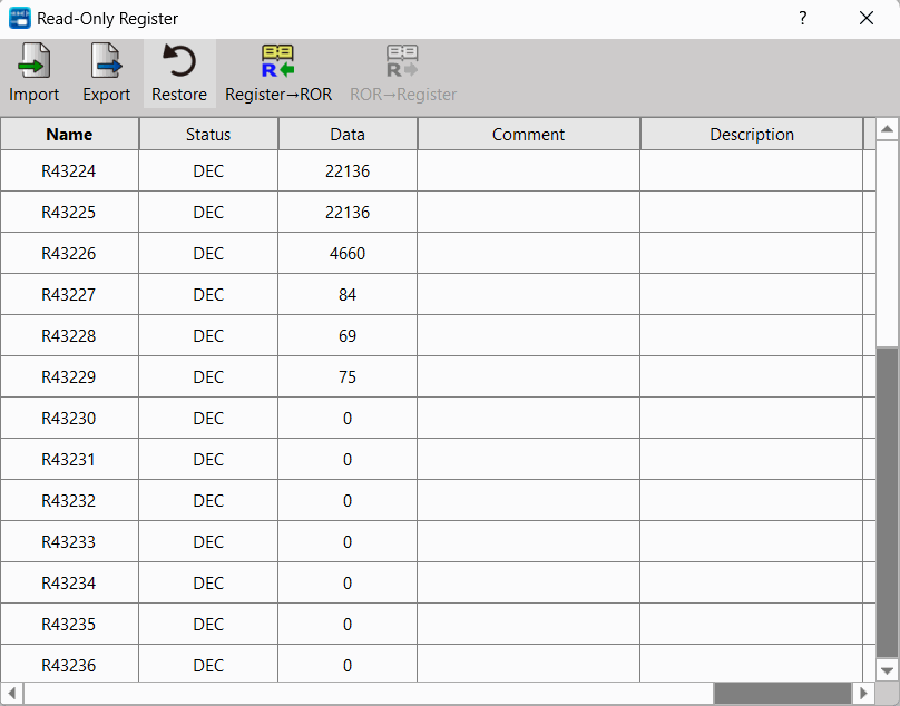
Fig. 61: Read-only Register
|
Item |
Description |
|
Export/Import |
Notes and description of export/import |
|
Restore Old Value |
Restore the data to the one just entered the ROR window |
|
Register→ROR |
Synchronize general register value to read-only register |
|
ROR →Register |
Synchronize read-only register value to general register |
5-4 Server Configuration
Provides users with the settings related to the server on the PLC.
Click [Project] → [Server Configuration].
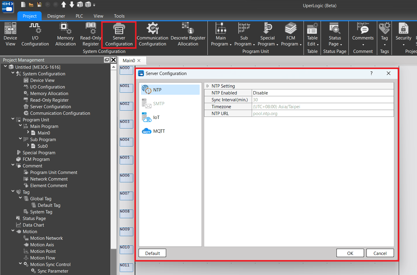
Fig. 62: Server Configuration
Users can apply the communication settings to configure NTP, SMTP, IoT and MQTT.
5-4-1 Network Time Protocols (NTP)
Provides users to set NTP parameters on PLC.
Click [Project] → [Server Configuration] → [NTP].
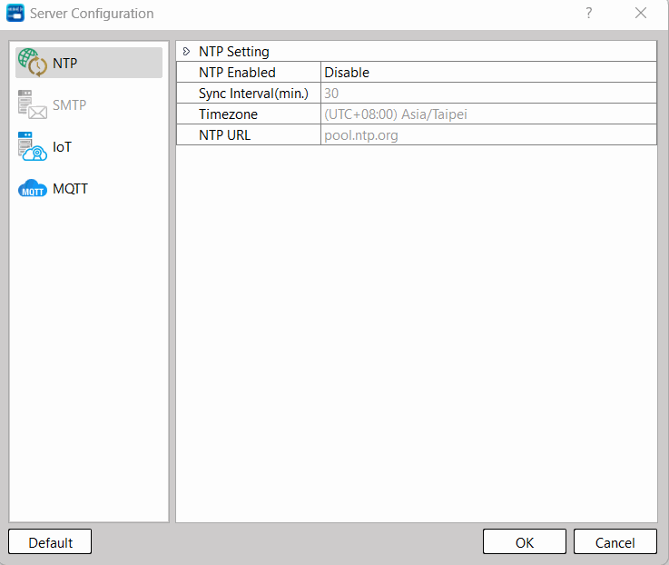
Fig 63: Setting NTP
5-4-2 IoT
Provides users with setting the IoT parameters on the PLC. When monitoring or editing online, the HWID of the PLC can be viewed and copied.
Click [Project] → [Server Configuration] → [IoT]
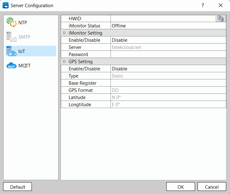
Fig. 64: Setting IoT
5-4-3 MQTT
MQTT is a communication protocol designed for IoT, characterized by simplicity and lightness. It is suitable for applications in environments with limited hardware resources and network bandwidth, and can meet the needs of remote monitoring and data exchange.
The mechanism of message transmission is publish/subscribe model, and each message must be identified by a topic name. The client is the publisher and the subscriber, the Publisher publishes a message with a topic, and the Subscriber subscribes to a topic; the server side is a Broker, which is responsible for receiving the publisher’s message and forwarding it to Subscribers for the corresponding topic.
Provides users with setting the MQTT parameters on the PLC
Click [Project] → [Server Configuration] → [MQTT]
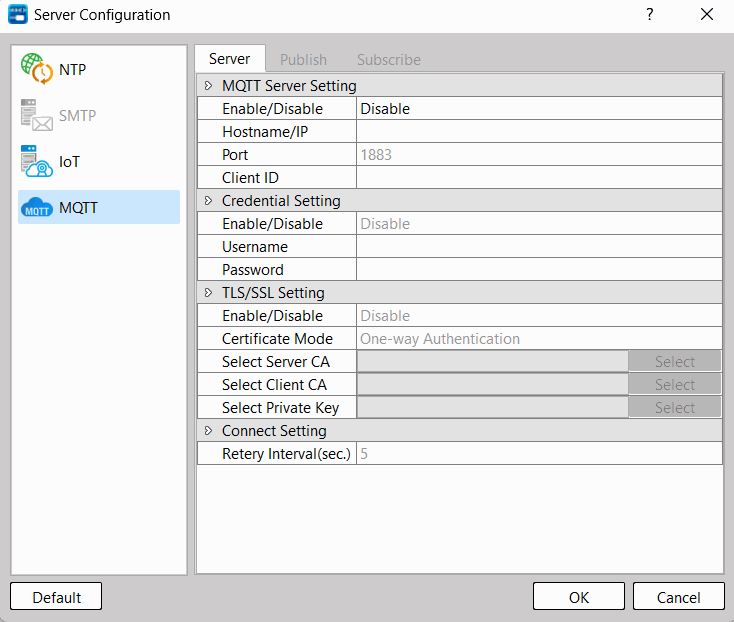
Fig. 65: Setting MQTT
|
Page |
Property |
Description |
|
MQTT Server Configuration |
Enable/Disable |
This is the main switch of the MQTT function. Only after enabling it can you set the detailed fields, as well as related topic publishing and topic subscription. |
|
Host (IP or URL) |
Set the Broker host address, you can fill in the IP or URL. |
|
|
Port No. |
Set the connecting port of Broker. The default is 1883. |
|
|
Client ID |
Client-specific identification code |
|
|
Authentication |
Enable/Disable |
Enable/Disable authentication |
|
User Name |
Input Broker-specified user name. |
|
|
Password |
Input the password specified by the Broker, and it will be kept secret in cipher text after entering. |
|
|
TLS/SSL Configuration |
Enable/Disable |
Enable/Disable TLS/SSL |
|
Identification Mode |
One-way and two-way identification are optional. |
|
|
Select Server Certificate |
Use server authentication. Import the required documents. |
|
|
Select Client Certificate |
Use client authentication. Import the required documents. |
|
|
Select Private Key |
Use client authentication. Import the required private key. |
|
|
Connection Setting |
Reconnection Interval (seconds) |
The interval between reconnections if the MQTT connection is disconnected, in seconds. |
Topic Publishing
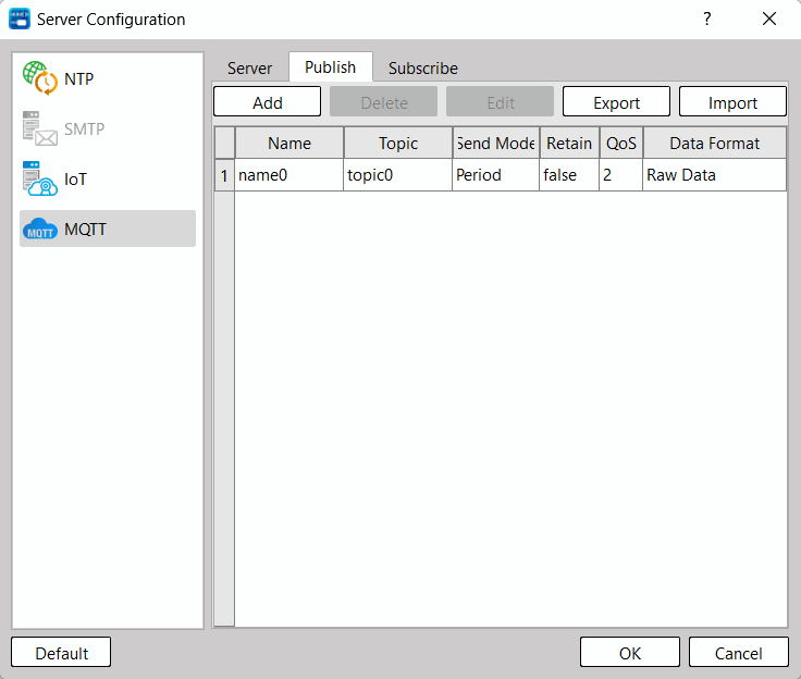
You can click [New] above to add a new theme, click the [Delete] button to delete the selected theme, click [Edit] or double-click the item in the theme list to edit the selected theme. If there is an existing theme in the theme list project, you can click [Export] to export all theme data into a CSV file in a specific format, and click [Import] to import a CSV file in a specific format to directly update the theme table.
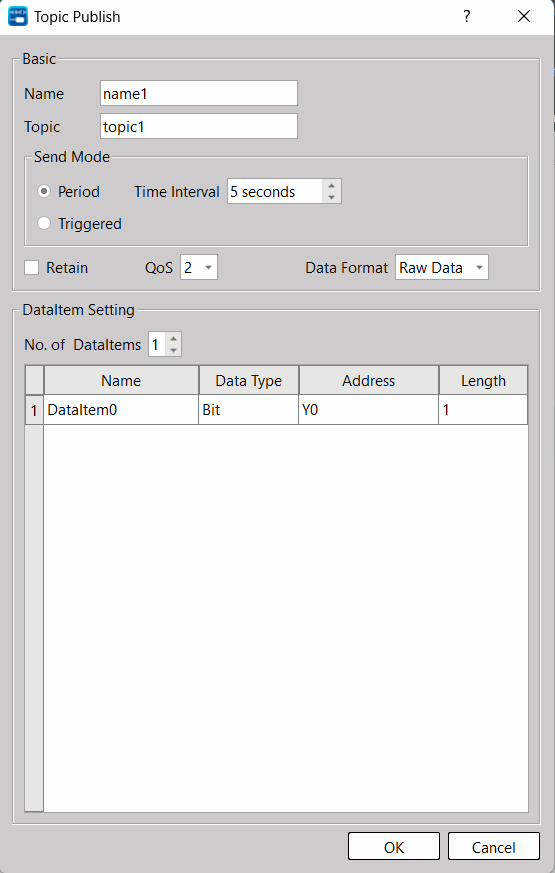
|
Page |
Property |
Description |
|
Basic |
Name |
Set the name of the topic, which can be used as a description |
|
Topic |
The topic used by MQTT to send messages. (Note: #, + are wild characters and cannot be used) |
|
|
Sending Mode |
Cyclic: Send messages periodically, and you can set the interval in seconds. |
|
|
Value change trigger: A message will be sent only when the value of the data item changes. |
||
|
Keeping Message |
Determines whether MQTT messages should be kept on the server. If checked, the server will save the subject message. Afterwards, if there are new subscribers, or previously disconnected subscribers reconnect, they will receive the latest reserved message. |
|
|
QoS |
Set the Quality of Service of MQTT, which is divided into three levels: Grade Description 0: The message is sent only once, delivery is not guaranteed, and will not be repeated. 1: The message delivered at least once, guaranteed delivery, may be repeated. 2: The message is delivered exactly once, and it is guaranteed to be delivered and will not be repeated. |
|
|
Data Format |
Raw Data、JSON、User define |
|
|
Data Item Setting |
Number of Data Item |
Sets the number of data items for this topic. |
|
Name |
The name of the data item cannot be blank, and each item name must be unique, and the item name can be entered directly. |
|
|
Data Type |
There are [bit], [16-bit BCD number], [16-bit integer], [16-bit positive integer], [32-bit BCD number], [32-bit integer], [32-bit positive integer], [32-bit floating point] and [Ascii] can be selected. |
|
|
URL |
According to the data type, the user can set the address of each data item. |
|
|
Length |
Users can determine the address length of this data item. |
Topic Subscription
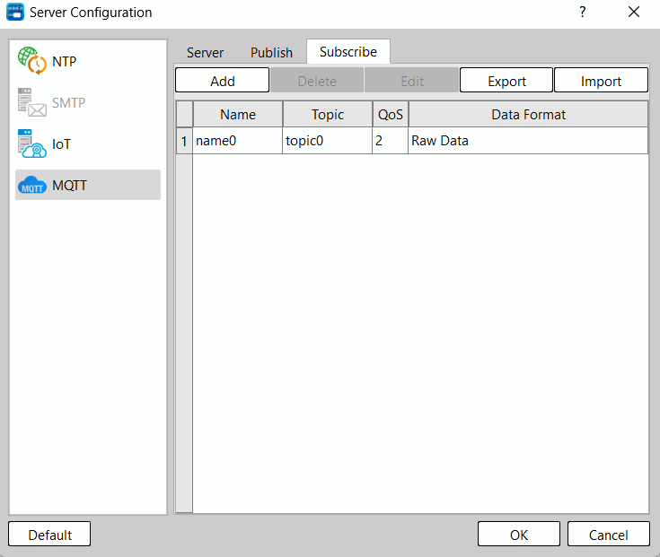
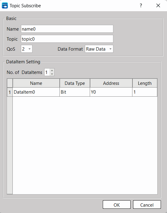
|
Page |
Property |
Description |
|
Basic |
Name |
Set the name of the topic, which can be used as a description |
|
Topic |
The topic used by MQTT to send messages. (Note: #, + are wild characters and cannot be used) |
|
|
QoS |
Set the Quality of Service of MQTT, which is divided into three levels: Grade Description 0: The message is sent only once, delivery is not guaranteed, and will not be repeated. 1: The message delivered at least once, guaranteed delivery, may be repeated. 2: The message is delivered exactly once, and it is guaranteed to be delivered and will not be repeated. |
|
|
Data Format |
Raw Data or JSON |
|
|
Data Item Setting |
Number of Data Item |
Sets the number of data items for this topic. |
|
Name |
The name of the data item cannot be blank, and each item name must be unique, and the item name can be entered directly. |
|
|
Data Type |
There are [bit], [16-bit BCD number], [16-bit integer], [16-bit positive integer], [32-bit BCD number], [32-bit integer], [32-bit positive integer], [32-bit floating point] and [Ascii] can be selected. |
|
|
URL |
According to the data type, the user can set the address of each data item. |
|
|
Length |
Users can determine the address length of this data item. |
5-5 Communication Configuration
It allows the user to configure the corresponding relationship between Register address and Modbud address in PLC.
Click [Project] → [Communication Configuration]
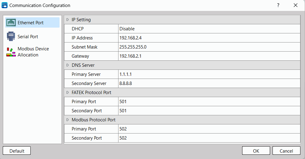
Fig. 66: Communication Configuration
Users can use communication settings to configure Ethernet, serial port and Modbus addresses.
5-5-1 Ethernet Port
The parameter allowing users to set up the network port on PLC.
Click [Project] → [Communication Configuration] → [Ethernet Port Setting]
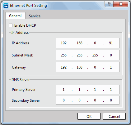
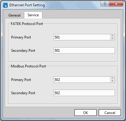
Fig. 67: Setting network station number
|
Page |
Property |
Description |
|
General |
Enable DHCP |
Enable/disable dynamic host setting protocol |
|
IP address |
Setting network address |
|
|
Subnet mask |
Setting subnet mask |
|
|
Preset gate |
Setting preset gate |
|
|
Regular server |
Setting regular DNS server |
|
|
Other |
Setting other DNS server |
|
|
Service |
Main connection port |
Setting regular network connection port for FATEK communication protocol |
|
Other connection port |
Setting fixed network connection port for FATEK communication protocol |
|
|
Main connection port |
Setting regular network connection port for Modbus communication protocol |
|
|
Other connection port |
Setting fixed network connection port for Modbus communication protocol |
Table 17: Setting Network Station Number Table
5-5-2 Serial Port
Provides users with setting the parameters of the serial port on the PLC.
Click [Project] → [Communication Configuration] → [Serial Port]
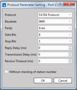
Fig. 68: Setting serial port parameter
|
頁面 |
屬性 |
敘述 |
|
Port1 Port2 |
Basic Settings_Baud Rate |
Setting Baud Rate |
|
Basic Settings _ Check bit |
Setting Check bit |
|
|
Basic Settings _Data bit |
Setting Data bit |
|
|
Basic Settings _Stop bit |
Setting Stop bit |
|
|
Basic Settings _ Response Delay Time (ms) |
Setting Response Delay Time |
|
|
Basic Settings _Sending Delay Time (ms) |
Setting Sending Delay Time |
|
|
Basic Settings _ Response error time out (ms) |
Setting Response error time out |
|
|
Advanced Settings _Check Station No. |
Whether to check the station number |
|
|
Advanced Settings_ Communication Protocol |
Setting Communication Protocol |
|
|
Station No. |
Station No. Setting |
Scope: 0-254 |
Table 18: Serial port parameter setting
5-5-3 Modbus Device Allocation
It allows the user to configure the corresponding relationship between Register address and Modbud address in PLC.
Click [Project] → [Communication Configuration] → [Modbus Device Allocation]
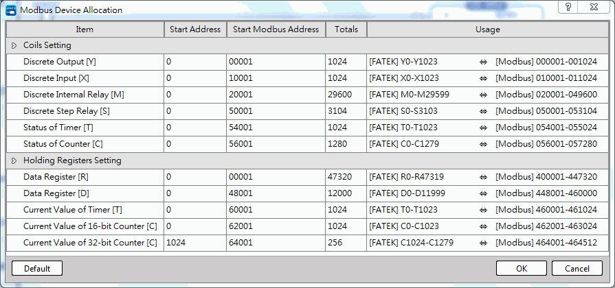
Fig. 69: Modbus address preset configuration
The preset configuration enables all of the Register addresses on PLC to communicate with the Modbus address. If the user wishes to reduce the number of Register used for communicating with Modbus address or to change the corresponding address, then the user may edit its own configuration type.
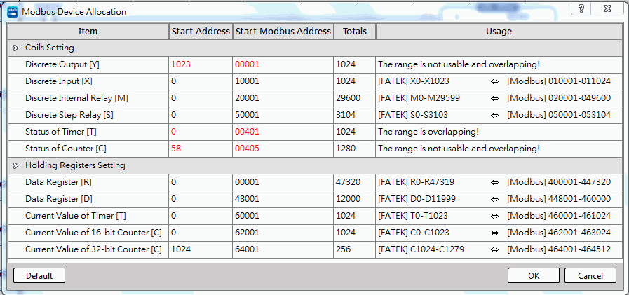
Fig. 70: Displaying setting error
If the address created by the user is incorrect, then the system will indicate the incorrect portion in red letter and will also display the error message.
|
Type |
Description |
||||||||
|
Item |
Explain the type of the contact that will be listed in this column. |
||||||||
|
Home address |
Create the home address that will correspond to the contact or the Register (preset as zero). |
||||||||
|
Modbus home address |
Create the Modbus home address that will correspond to the contact or the Register. |
||||||||
|
Sum |
Create the Modbus sum (preset as maximum value) that will correspond to the contact or the Register. |
||||||||
|
Servicing status |
Under normal condition, it displays the Modbus address status that will correspond to the contact or the Register. If the setting is wrong, then it will display the corresponding error.
|
Table 19: Items required for Modbus address configuration
Tip: press ← → to switch chapters, Ctrl+K to search