This section describes the operating procedure required for executing the PLC online and offline as well as the PLC program starting and stopping operations. Provided below are detailed operation methods required for executive the respective communication
11-1 Connection
It allows the user to connect with the PLC function for changing current online parameters and creating online list, etc.
From the function bar [PLC] → [Connection Parameter], you can set the default connection parameter, which can be used directly for subsequent connections without additional settings.
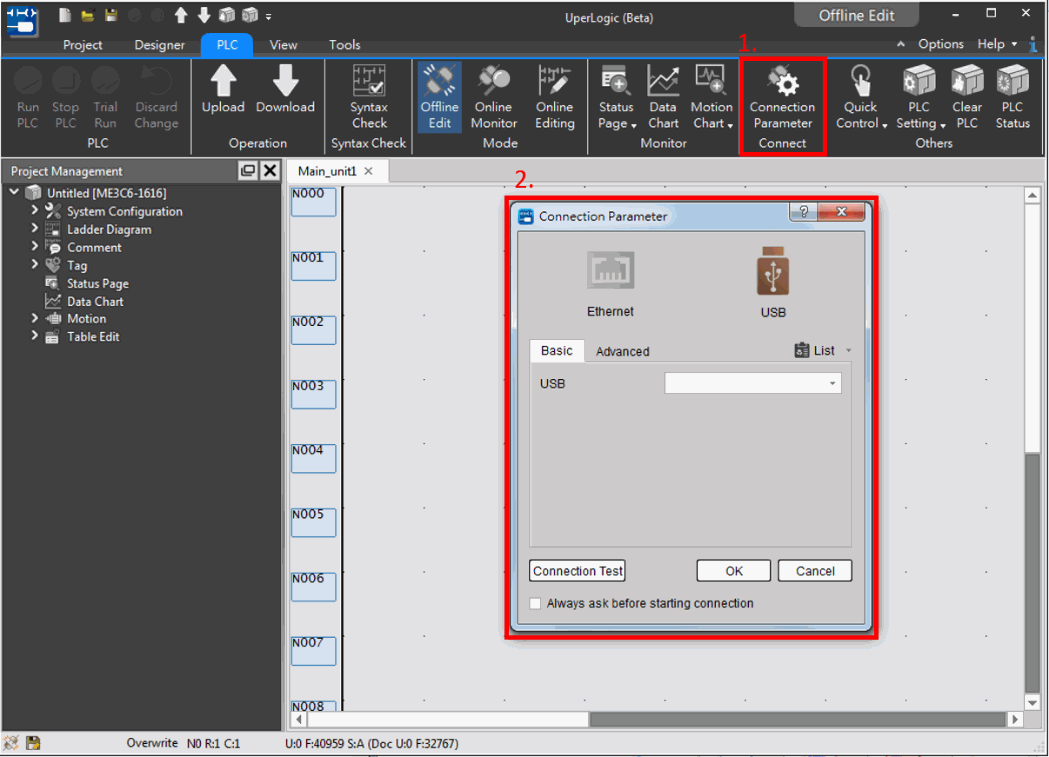
Fig. 240: Connection Parameter
|
Page |
Connection Type |
Attribute |
Description |
|
Network Connection |
Select the network interface card users want to use. |
||
|
Basic |
Ethernet |
Type |
Network online type, in TCP or UDP. |
|
IP Address |
Connected PLC network address |
||
|
Communication Port |
Connected PLC network port. |
||
|
|
Display the current network interface card information. |
||
|
|
Search the PLC network address existing on the network. |
||
|
USB |
USB |
Select the M-PLC USB port that is currently connected to the computer. |
|
|
Advanced |
Timeout (ms) |
PLC response timeout setting, the setting range is 100-30000 ms. |
|
|
Retest Frequency |
Communication failure retest time setting, the setting range is 0-10 times |
||
|
Command Delay (ms) |
The delay time setting of each communication, the setting range 0-1000 ms. |
||
|
Other Settings |
Connection List |
A list of frequently used connections can be set, and the connection information can be quickly brought in by clicking the drop-down menu option. |
|
|
Connection Test |
Use the current parameters to perform a quick connection test to confirm that the connection parameters are valid parameters. |
||
|
Be sure to ask before connecting |
When checked, the connection parameter window will be displayed before each connection action. If it is not checked, the previous connection parameters will be used to directly connect. |
||
 Network Connection Info
 Search
Connection List
Click [Connection Parameter List] → [Connection List] in scroll-down menu and you will be allowed to create the Connection List.
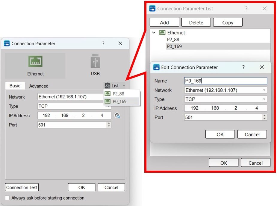
Fig. 241: Connection Parameter List
Connection Test
Click [Connection Parameter List] → [Connection Test] to perform a quick connection test with the current parameter.
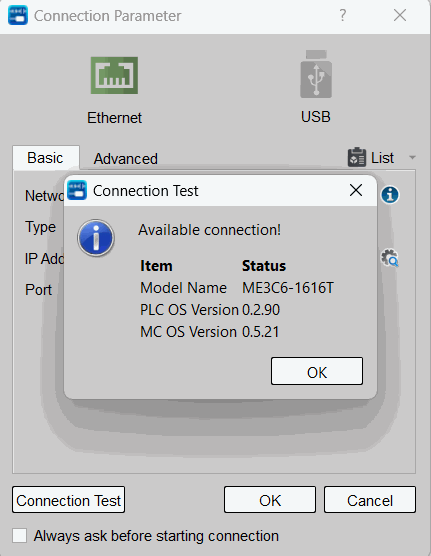 [
11-2 Offline Edit
Under PLC online status, click “PLC” → “Offline edit” in function toolbar and you will be allowed to execute the offline editing.
11-3 Upload
Such function allows users to upload the PLC project to PC for preparing backup copy or for inspection.
The operation process differs depending on whether the project is opened or not, as detailed below:
11-2-1 Upload with Open Project
- Select the tab page [PLC] → [Upload], and use the set connection parameters to connect.
- After connecting, compare the currently opened project with the PLC project.
- When the comparison is the same, [The current project matches the connected PLC] will show.
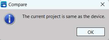
- When the compare is not matched, a compare window will be displayed to allow the user to select the part to be uploaded.
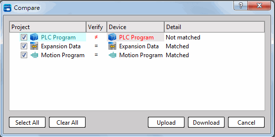
Fig. 242: Selecting the uploaded data
- Click [Upload] to start uploading until the progress window is completed.
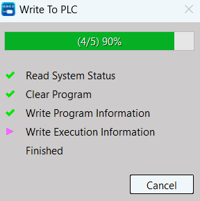
11-2-2 Upload with Closed Project
- Select the tab page [PLC] → [Upload]
- Ask “Do you open the relevan project?”
- Click [Yes] → The action is the same as Section 11-3-1.
- Click [No] → The connection parameters will be forcibly asked, and the connection will be performed using the set connection parameters.
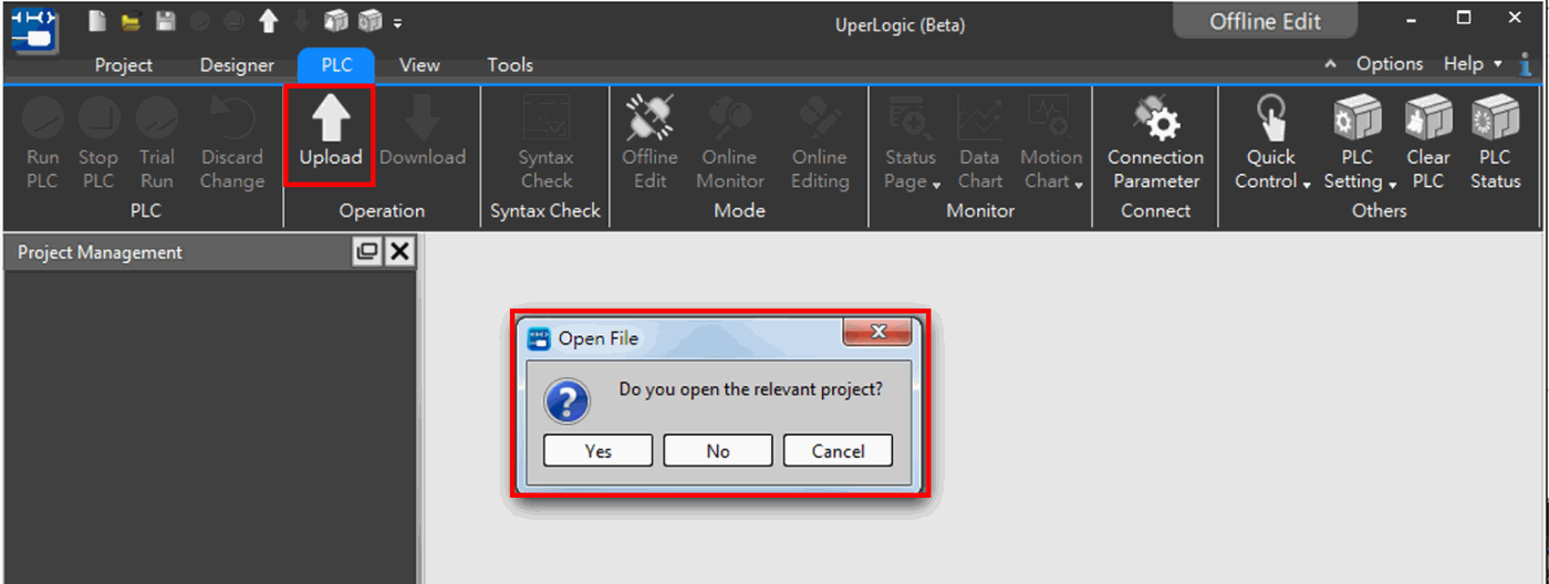
Fig. 243: Opening the relevant project
- After connecting, the user can choose the data to be uploaded.
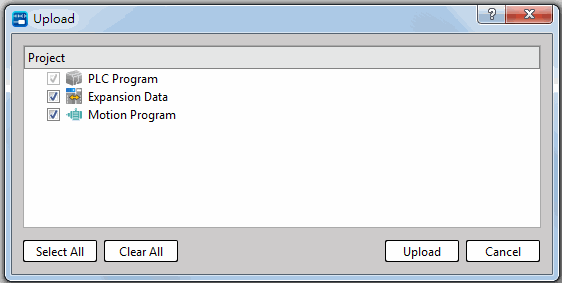
Fig. 244: Uploading the data
- Click [Upload] to start uploading until the progress window is completed.
11-4 Download
Such function allows the user to download the PLC project being planned in PC to the PLC.
- Select the tab page [PLC] → [Upload], and use the set connection parameters to connect.
- After connecting, compare the currently opened project with the PLC project.
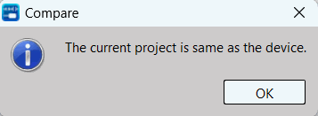
- When the compare is the same, [The current project matches the connected PLC] will show.
- When the compare is not matched, a compare window will be displayed to allow the user to select the part to be downloaded.
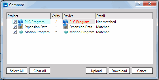
Fig. 245: Selecting the data to be downloaded
- If the compare is different, and there are syntax errors or inconsistent modules, only the upload function is provided.
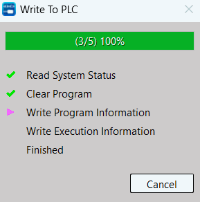
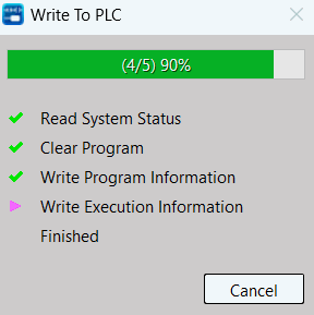
- Click [Download] to start downloading until the progress window is completed.
11-5 Run/Stop PLC
Run PLC
When operated under online monitoring status, click [PLC] → [Run] in function toolbar or you may press “F9” quick key.
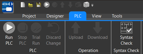
Fig. 246: Running PLC
Stop PLC
When operated under online monitoring status and when PLC is under Running Mode, click [PLC] → [Stop] in function toolbar.
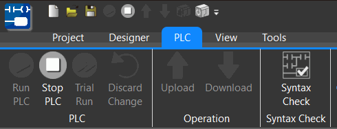
Fig. 247: Stopping PLC
11-6 Clear PLC
When operated under online status, click [PLC] → [Clear PLC Data] in function toolbar, and [Clear All (Initialization)], [Clear Program Only], [Clea Registers Only], and [Clear Coils Only] options will appear as below:
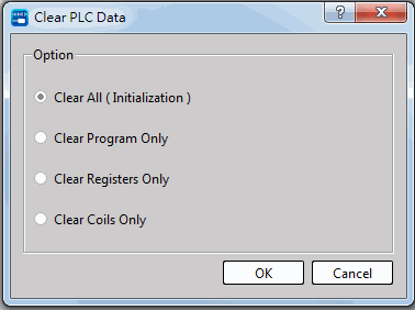
Fig. 248: Clearing PLC data
|
Function |
Description |
|
Clear All |
Clear all PLC data and restore factory settings |
|
Clear Program Only |
Clear the program data in the PLC, including motion control data. |
|
Clea Registers Only |
Reset all register values in the PLC. |
|
Clear Coils Only |
Reset all coils in the PLC. |
11-7 PLC Status
When operated under online status, click [PLC] → [PLC Status] in function toolbar and the data will appear as below:
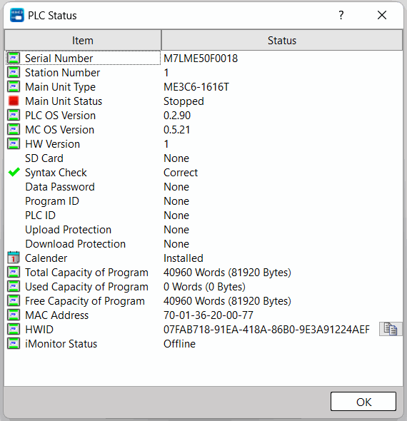
Fig. 249: PLC status
|
Function |
Description |
|
Station Number |
Station number of the connected main unit. |
|
Main Unit Type |
Type of the connected main unit. |
|
Main Unit Status |
Working status of the connected main unit. |
|
PLC OS Version |
Firmware version of the connected main unit. |
|
MC OS Version |
Motion control firmware version of the connected main unit. |
|
HW Version |
Hardware version of the connected main unit. |
|
Memory Pack |
Whether the connected main unit is installed with a memory card. |
|
Syntax Check |
Program syntax checking condition of the connected main unit. |
|
Data Password |
Whether to set data password on the connected main unit. |
|
Program ID |
Whether to set Program ID on the connected main unit. |
|
PLC ID |
Whether to set PLC ID on the connected main unit. |
|
Upload Protection |
Whether to set upload protection on the connected main unit. |
|
Download Protection |
Whether to set download protection on the connected main unit. |
|
Calendar |
Whether the connected main unit is installed with RTC. |
|
Total Capacity of Program |
Total program capacity of the connected main unit. |
|
Used Capacity of Program |
Used program capacity of the connected main unit. |
|
Free Capacity of Program |
Free program capacity of the connected main unit. |
|
MAC Address |
MAC address of the connected main unit. |
|
HWID |
HWID of the connected main unit. |
|
iMonitor Status |
The iMonitor status of the connected main unit, including offline, online, connecting and error status. |
11-8 PLC Setting
11-8-1 PLC ID Setting
When the PLC ID set by the PLC is different from the Program ID, the PLC cannot operate normally. The PLC ID can be set through the execution function bar [PLC]→[PLC Setting]→[PLC ID]. The ID rule is setting with 8 uppercase alphanumeric letters.
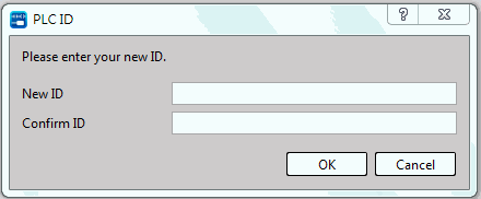
Fig. 250: Setting PLC ID
11-8-2 RTC Setting
When the PLC is under “Online” and “Run” status, the user will be allowed to click [PLC] → [PLC Setting] → [RTC]. After that, the following window will appear for the user to set up the perpetual calendar time required for the PLC.
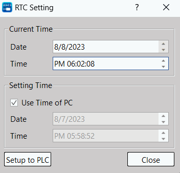
Fig. 251: Setting RTC
|
Function |
Description |
|
Current Time |
Date and time of the currently connected main unit. |
|
Setting Time |
To set the date and time to the currently connected main unit. |
|
Use Time of PC |
When checked, the current computer time will be used as the setting time. |
|
Setup to PLC |
When clicked, the setting time will be written directly to the currently connected main unit. |
11-8-3 Firmware Update
Select the function bar [PLC] → [PLC Setting] → [Firmware Update], and select the corresponding firmware file and start updating, until the progress window is closed and the prompt window showing the completion of the update is displayed. Wait until the light is displayed normally and then just restart the main unit. The extension of the firmware update file is *.os.
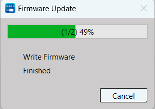
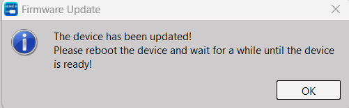
Fig. 252: Firmware Update
11-9 Quick Control
The Quick Control operation is for the convenience of the user. When the connection parameters are set correctly, the PLC can be connected to perform some operations without complete synchronization of data.
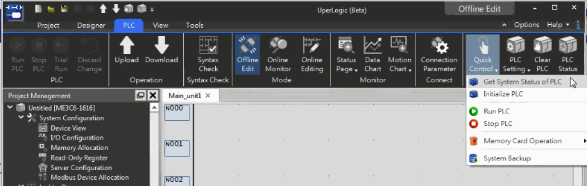
Fig. 253: Quick Control
11-9-1 Get System Status of PLC
Under the state of offline edit, when the connection parameters are set correctly, click [PLC] → [Quick Control] → [Get System Status of PLC] on the function bar to read various information of the PLC under offline conditions , the content is the same as section 11-7.
11-9-2 Initialize PLC
Under the state of offline edit, when the connection parameters are set correctly, click [PLC] → [Quick Control] → [Initialize PLC] on the function bar to initialize the PLC under offline conditions.
11-9-3 Run PLC
Under the state of offline edit, when the connection parameters are set correctly, click [PLC] → [Quick Control] → [Run PLC] on the function bar to run PLC under offline conditions.
11-9-4 Stop PLC
Under the state of offline edit, when the connection parameters are set correctly, click [PLC] → [Quick Control] → [Stop PLC] on the function bar to stop PLC under offline conditions.
11-9-5 Memory Card Opearation
Under the state of offline edit, when the connection parameters are set correctly, click [PLC] → [Quick Control] → [Memory Card Opearation] on the function bar to configure related PLC settings under offline conditions.
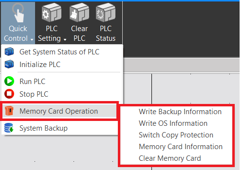
Fig. 254: Memory card configuration
For detailed setting description, please refer to Chapter 14-2.
11-10 Online Edit
The online editing function can directly change the program and project content on UperLogic page, so that users can make on-site adjustments during the final debugging of the program design.
When using the online editing function in the running state of the PLC, if the wrong method was used, it may bring great harm to the device and operators, and users need to carefully check the content during operation.
11-10-1 Starting Online Edit
The process is shown below:
- Click to execute the function bar [PLC] → [Online Edit] when the PLC is connected.
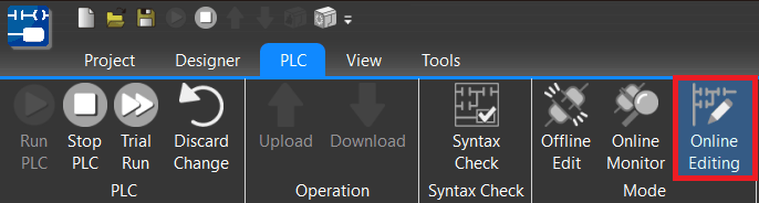
Fig. 255: Online Edit
- After connecting, compare the current project with the PLC project.
- If the comparison is the same, skip directly to Step 4。
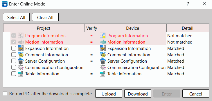
- When the comparison is different, the compare window will be displayed to prompt the different parts. Since it is necessary to synchronize the project and PLC data to enter the online editing mode, the user can choose to download the project or upload the PLC data for synchronization.
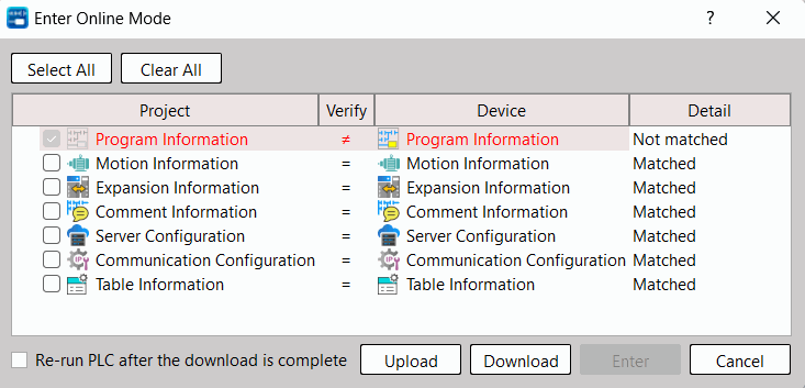
-
- When the comparison is different and the syntax check is wrong or the module list is inconsistent, you can only enter the online editing mode after selecting to upload PLC data for synchronization.
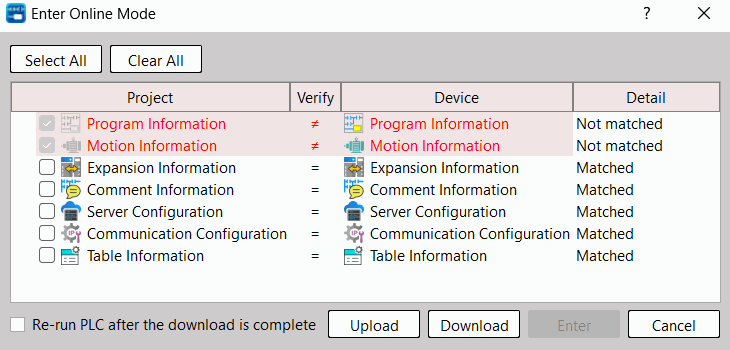
- After clicking the sync direction, wait for the progress window to complete.
- After the synchronization is completed, it will enter the online editing mode and display the PLC status window.
11-10-2 Trial Run
When editing online, the changed part of the project or program will not be written into the PLC immediately, but must be written to the PLC running section through the trial run mechanism to make the current changed part take effect. Click [PLC] → [Trial Run] in the function bar to perform a test run on the PLC.
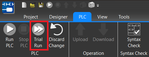
Fig. 256: Trial Run
11-10-3 Discard Change
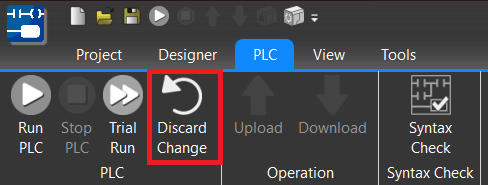
When editing online, if the debugging result after editing is not as expected, the project can be restored to the previous state through [Discard Change]. This operation only restores the project, if you need to restore the PLC data, you need to perform a trial run again.
Click [PLC] → [Discard Change] on the function bar to restore the previous status.
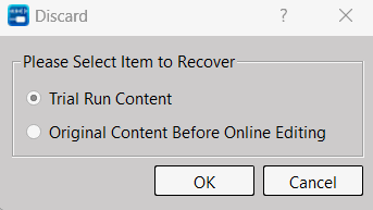
Fig. 257: Discard Change
|
Function |
Description |
|
Content of the Previous Trial Run |
Restore to the content of the project at the time of the previous trial run. |
|
Content before Online Editing |
Restore to the project content when entering online editing. |
11-10-4 Finishing Online Edit
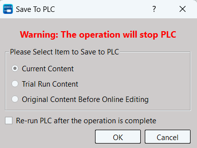
The debugging content during online editing will only exist in the PLC running section, so when you leave the online editing mode, you need to re-download the current project content to the PLC. Please note: this operation will stop the action. Switching from [Online Edit] to [Offline Edit] or [Online Monitor], the following prompt window will appear, allowing the user to select the data to be stored in the PLC.
|
Function |
Description |
|
Current Content |
When the current project content is written to the PLC. |
|
Contents of Previous Trial Run |
Restore to the content of the project during the previous trial run and write it to the PLC |
|
Content before Online Edit |
Restore to the project content when entering online editing and write it to PLC |
|
Restart the PLC after the operation is complete |
When checked, restart the PLC after the write to PLC operation is completed |
Tip: press ← → to switch chapters, Ctrl+K to search