1-10 Introduction
This chapter will explain the methods of applying basic ST Language programming.
3-1-1 Character Encoding
ST editor supports Unicode(encode in UTF-8). Supports basic characters and most symbols in Japanese, English, Chinese and other languages that appear in program editing. In addition to being used for comments, they can also be used in labels or program and table names.
3-1-2 Composing Units
The ST language uses the combination of the following symbols to describe the program. Later chapters will explain in detail.
|
Type |
Example |
Referrence |
|
|
Computing Symbols |
+、-、*、/、AND、&、OR、|、XOR、MOD、 <=、 >=、<>、++、–、<<、>>、NOT、:=、(、) |
||
|
Keywords that control syntax (Standard identifier being defined) |
IF、ELSEIF、END_IF CASE、OF、END_CASE WHILE、FOR、END_WHILE END_FOR LBL GOTO、CALL、 LBL_F、GOTO_F IF_RISINGTRIGGER IF_FALLINGTRIGGER |
||
|
Identifier |
Variables, Hardware Register, IO Discretes, Indirect Address…etc. (Labels, Elements…etc.) |
X0、Y0、M100、R0、DR0、、D0、DD0、IM0…etc Tag (Register any name) |
|
|
Function Call (FB) |
1. System built-in Function 2. (User-created FB Function library) |
||
|
Constant |
Interger: Defaulted as “signed int” Ex: R0:=1; R0:=-2; “Unsigned int” Ex: Tag0:=0xFF; String: Use only on Label Goto, LBL…etc Bit (Bool) Type: TRUE、FALSE Float: 32-bit Float Constant ex: TagFloat1:=1.1; |
||
|
Delimiter |
“:” appears in CASE OF 分隔“,” Passing multiple function parameters |
||
|
Left/Right Round Brackets |
“(“ , “ )”
ex: Fun0 ( S:=R0, D:=R1 );
R0:= (1+R0)*R2; |
||
|
RETURN |
Used in Sub-program or FB. To immediately leave the program section. |
||
|
“;” the end of the statement |
To mark the end of a sentence running at one end. |
– |
|
Spaces, newlines and comments can be freely inserted between each symbol.
|
Type |
Example |
Referrence |
|
Space |
Space (Halfwidth/Fullwidth), TAB |
- |
|
Newline |
Newline Code |
- |
|
Comment |
//、(* …. *) |
1-11 Statement
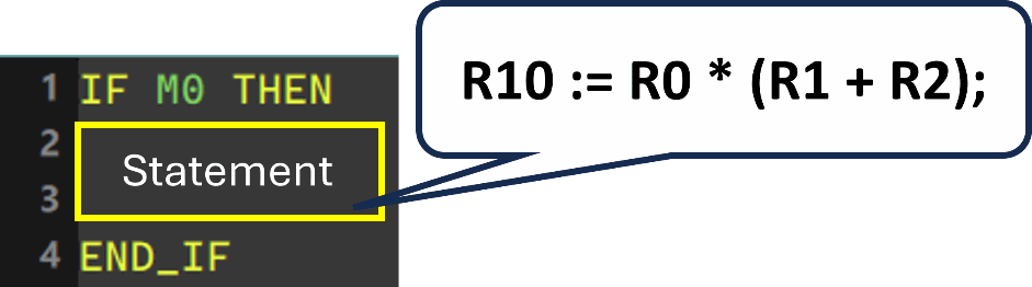 “Statement” is the most basic execution unit in ST Language, which represents a complete work to be executed. A complete statement is not limited to the same line of words; however, it must be ended with “;.” In addition, a statement is also allowed to contain multiple or multi-level sub-statement, and regardless of the position of the statement, it must be followed by a “;” symbol at the end.
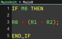
A complete statement is equivalent to a ladder diagram section (NETWORK) with complete functions, and it must be able to clearly express one work. Take the statement in the below program as an example, the work it performs is to compute the content value of each device according to the order R0*(R1+R2) expressed in the mathematical formula, and assign the result of the operation to the R10 device. However, although the content in the red frame in the figure below is legal, it is not a complete statement but an Expression, which represents only a value of a mathematical computation, but not a specific work.
Shown below are some statements of Uperlogic ST Language: 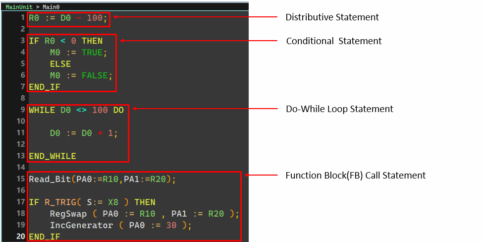
|
Type |
Content |
Example |
|
|
Distributive Statement |
Substitute the result on the right into the variable on the left. |
||
|
Flow Control Syntax |
Conditional Statement (IF, CASE) |
Select the execution syntax based on the condition. |
|
|
Do-While Statement (FOR, WHILE) |
Execute multiple times depending on the end condition. |
||
|
Sub-program Statement |
Function Block Call Statement |
Call FB(FCM) |
|
|
Label Statement |
Call LBL |
||
|
Toolbox Statement |
Convenient statement to execute toolbox instructions |
||
Flow control syntax can be layered.
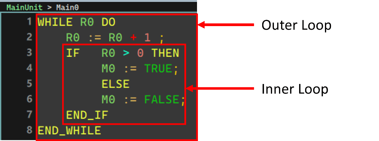 (It can be used in combination with Conditional statements and do-whlie statements))
1-12 Expression
“Expression” is a very important element in the structure of a statement and it represents a “value”, such as a Boolean value of TRUE or FALSE, or an integer value of 20 or -5. It can be an operation expreesion or a constant, and of course it can also be a variable symbol or device, depending on occasions. The following are some examples of expressions:
- M0 & M1 (Expression of Boolean) represents the Boolean value between the computation of M0 and M1.
- M0 = FALSE (Expression of Boolean) represents whether the condition “M0=FALSE” is true. When the value of M0 is ON, the Boolean value represented by this expression is FALSE; but when M0 is OFF, the Boolean represented by the expression will be TRUE because the condition is established.
- M0 (Expression of Boolean) directly takes the value of M0 as its representative Boolean value. When the value of M0 is ON, the Boolean value represented by the expression will be TRUE, and when M0 is OFF, the Boolean represented by the expression will be FALSE.
- D1 + D2 (Expression of Value) represents the result of adding D1 and D2.
- D0 (Expression of Value) directly takes the current value of D0 as its representative value.
- D2 = D0 + D1 (Expression of Boolean) is a relatively confusing Boolean expression, which represents whether the condition “D2=D0+D1” is true. When the result of adding D0 and D1 is equal to the current value of D2, the expression is TRUE; if the result of adding of D0 and D1 is not equal to the current value of D2, the expression represents FALSE.
- D2 := D0 + D1; (Statement, not Expression) is a complete statement rather than an expression, which represents the meaning of the work “Assigning the result of adding D0 and D1 to D2”; but this statement is also composed of the two expressions “D2” and “D0+D1.”
Position of the Expression used:
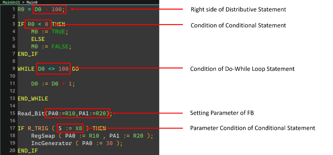
The below table shows Expression types:
|
Type |
Data Type of Expression (Computing Result) |
Example |
|
|
Operation Expression |
Arithmetic Expression |
Interger, real number…etc. (according to computing elements) |
R0+R2 |
|
Logic Expression |
Boolean (TRUE/FALSE) |
R0 AND R2 |
|
|
Compare Expression |
Boolean (TRUE/FALSE) |
R0 > R2 |
|
|
Basic Expression |
Variables, Constants |
Defined data type |
M0.R0.123.TRUE |
|
Function Call Expression |
Data type of return value |
Fcm0( PA0:= ,OUT0=> ); |
|
3-3-1 Opearation Expression
This section uses examples to explain how operation expressions are presented in the ST environment and the LD environment.
3-3-2 Arithmetic (+、-、*、/)
The four operation symbols are described using the same operation symbols (+, -, *, /) as the general arithmetic symbols.
For operations that cannot be described in LD diagrams, can be described concisely through single-line expressions.
Program Example:
Substitute the adding result of R0-R2 in R3
R3=R0+R1+R2
ST
R3:=R0+R1+R2;
LD

- When adding multiple operration expressions with one statement, the operation symbol with the highest priority will be processed. For the priority of the four operation symbols, please refer to the chapter on operands. When there are multiple operation symbols with the same priority, the operation starts from the leftmost operation symbol.。
Advanced Operation (Exponents)
Exponential or trigonometric operations using general-purpose functions.
|
Type |
Function Name |
Example |
|
|
General Expression |
ST |
||
|
Absolute Value |
ABS |
|X| |
ABS( D:= ); |
|
Square Root |
SQRT |
FSQR(S:= ,D:= ); |
|
|
Trigonometric Functions |
SIN、ASIN |
B=SIN A |
FSIN( S:= , D:= ); |
|
COS、ACOS |
B=COS A |
FACOS( S:= , D:= ); |
|
|
TAN、ATAN |
B=TAN A |
FTAN( S:= , D:= ); |
|
Program Example
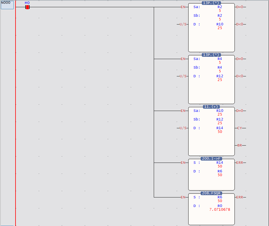
Find the length of the hypotenuse of a right triangle.
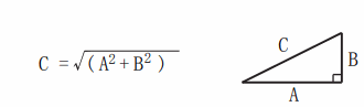
ST
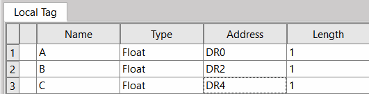
(To use floating point numbers, you need to register Tag first to change the data type.
ex: A= Float DR0、B= Float DR2、C= Float DR4)
FSQR( S:= A*A+B*B, D:= C);
LD
1-13 Operand and Operator
Operands and operators are the basic elements that make up an expression. The operand refers to the object involved in the operation, and the operator represents the operation performed. For example, in the expression “D0 + D”1, both “D0” and “D1” are operands, and the “+” sign is the operator. As seen from the examples in the previous section, an expression can be a combination of a group of operands and operators, but it can also be represented by an operand alone; while the operand can be a device, a variable symbol or a constant
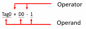
Like mathematical forms, operators themselves have a priority order for performing operations. When the priority levels are the same, the order of the operation will be from left to right. The following table is a list of operators in ST syntax in Uperlogic
|
Symbol |
Function |
Data Form |
Example of Expression |
Priority Level |
||
|
Operand |
Operation Result (Expression Value) |
Expression |
Value |
Highest |
||
|
() |
Prior block |
Not limited |
Not limited |
(D0 + 6)* 3 |
||
|
++,– |
To quickly add or subtract 1 |
Any value |
Any value |
++D0 D0++ |
||
|
– |
Numerical negative sign |
Any value |
Any value |
-D0 |
||
|
NOT |
Logic inversion |
Boolean |
Boolean |
NOT M0 |
TRUE |
|
|
* |
Multiplication |
Any value |
Any value |
D0*3 |
||
|
/ |
Division |
Any value |
Any value |
15/D0 |
||
|
+,- |
Addition, Subtraction |
Any value |
Any value |
D0+3 |
||
|
< , >,<=, >= |
Value compare |
Any value |
Boolean |
D0>2 |
||
|
=,<> |
Equal, Not Equal |
Any value |
Boolean |
D0<>2 |
||
|
Boolean |
M0=TRUE |
|||||
|
AND,& |
“and”operation |
Boolean or Value |
Boolean or Value |
M0&M1 |
||
|
OR, | |
“or”operation |
Boolean or Value |
Boolean or Value |
M0 OR M1 |
||
|
XOR XNOR |
“exclusive or” operation, “exclusive nor” operation |
Boolean or Value |
Boolean or Value Integer |
M0 XOR M1 |
||
|
MOD |
Value |
Value |
D0 MOD 3 |
|||
|
>>,<< |
Shift right/left 1 |
Any value |
Any value |
D0>>1 |
2 |
|
|
R_TRIG, F_TRIG |
Rising Edge Falling Edge |
Lowest |
||||
■ The part with the same background color have the same priority.
■ AND, OR, XOR, XNOR basically do the role of BitWise (ex R0 AND R1) and the result will be a value.
Unless the left and right sides are both Bool(bit) (ex. M0 AND M1) types, logic operations will be performed and the result will be a Bool(bit) value.
■ No support &&, ||, == syntax.
The individual Operator will be introduced later.
3-4-1 ( )
The function is the same as a mathematical formula, and the expression in the round brackets is prioritized for operation.
EX:
R0:= (R0+2)*3-(R2+3)*56 ; // R0=1;R2=2
// R0= – 271
3-4-2 Arithmetic +, -,* , /
Operate addition, subtraction, multiplication and division for the operators on both sides.
Calculate addition, subtraction, multiplication and division for the operands on both sides
EX:
R0:= 5+4-3*2/1 ;
// R0=3
3-4-3 Quick Addition and Subtraction ++, —
Specifically for operand + 1 or -1
Prefix Syntax:
++(Register)
–(Register)
The same result as (Register):=(Register)+1, but the speed is faster.
PostFix Syntax:
(Register)++
(Register)–
First take (Register) value → return → operate (Register):=(Register)+1
ex:
R0:=10;
R2:=10;
R100:=++R0; //// R100 is 11, R0 is 11
R102:=R2++; //// R102 is 10, R2 is 11
3-4-4 Value compare >=,<=,>,<
Compare the values on the left and right sides of the symbol. The left and right sides of two symbols need to be of the same type to be able to compare; otherwise there will be truncate or digital missing (float <->int)
The result will be TRUE/ FALSE ( 1/ 0)
EX:
M0:=R1 >= R2; /// If R1 is greater than or equal to R2, M0 will be TRUE ( 1 )
3-4-5 Equal to/Not equal to = , <>
Compare whether the left operator is equal to the right operators.
The result will be TRUE/ FALSE ( 1/ 0)
EX:
M0 := R0=100; // If R0 value=100, M0 will be TRUE ( 1 )
3-4-6 Bit shift left and right <<, >>
For the left-side value, shift left or right by the number of bits on the right side.
EX:
R10:=R0<<4; //R0=1(0b0_0001)
// R0 value will be shifted right with 4 bits, and assign to R10
// R10=16(0b1_0000)
P.S. R0 will not be changed
3-4-7 Negation of Operand NOT
Perform Bitwise NOT operation on the right operand.
EX:
R0:=NOT R2; // Do “one’s complmenet” to the value in R2 and save it to R0
R2=1(0b0_0001) => NOT R2= -2(0b1111_1110)
M0:= NOT ( M0 OR M2 ); // M0 OR M2 result is negated and stored in M0
3-4-8 Negative Sign of Operand –
Perform negation (sign reversal) on the right operand.
EX:
IF R_TRIG( S:=M1 ) THEN
R0:=-R2; //R2=1 0b0_0000_0000_0001)=> R0=-1(0b1111_1111_1111_1111)
END_IF
3-4-9 Assign Value :=
Assign the right value (variables) to the left variable of the symbol.
EX:
R1:=R0; // Move R0 to R1
R1:=1; // Set R1 as integer 1
3-4-10 Logic Operand AND ( & )、OR ( | )、XOR、XNOR
Perform logic operations (Bitwise) on the left and right operators, and the result of the value will be the same as the type of the operator.
EX:
R0:= R1 AND R2; // Perform bitwise AND operation on the values of R1 and R2 and store them in R0
// If R1=1(0b0_0001) R2=15(0b0_1111) then R0 =1(0b0_0001)
DR0:= R10 & DR12;
// Perform bitwise AND operation on the values of R10 and DR12 and store them in DR0
// If R10=1118481(0x11_1111H) DR12=69905(0x1_1111H) Then DR0 =4369(0x1111H)
R0:= R1 | R2; // Perform bitwise OR operation on the values of R1 and R2 and store them in R0
// If R1=1(0b0_0001) R2=15(0b0_1111) then R0 =15(0b0_1111)
DR0:= DR10 OR R12;
// Perform bitwise OR operation on the values of R10 and DR12 and store them in DR0
// If DR10=4369(0x1111H) R12=69905(0x1_1111H) Then DR0 =4369(0x1111H)
R0:= R1 XOR R2;
// Perform bitwise inverse OR operation on the values of R1 and R2 and store them in R0
// If R1=1(0b0_0001) R2=15(0b0_1111) then R0 =14(0b0_1110)
R0:= R1 XNOR R2;
// If R1=1(0b0_0001) R2=15(0b0_1111) then R0 =-15(0b1111_0001)
3-4-11 Remainder MOD
Operates the remainder of the left and right operands which are equal to C’s “%” symbol
EX:
R0:= R1 MOD R2 ; // R0 is the remainder after dividing R1 by R2
// R1=10,R2=3 The quotient of 10/3 is equal to 3, the remainder is equal to 1, R0=1
1-5 Comment
Comments are those used by program developers for easy maintainance in the future. There are single-line or multiline comments appeared with light gray text, and these parts will be ignored by the editor and will not generate operating data.
3-5-1 Single-Line Comment //
Ligh gray will appear after the symbol, and will not generate the operating program codes.
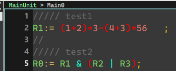
3-5-2 Multiline Comment (* *)
A continuous comment that can be multiple-line (or a single line), and the text between these two symbols will be seen as a comment.
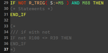
P.S. Users can also use quick keys (Ctrl+ / ) to comment on the selected rows and columns in batches (add/remove).
1-6 Flow Control and Loop
When writing ST, some conditions or loop control are usually required for easier design.
Introduction as shown below:
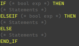
3-6-1 IF ELSE
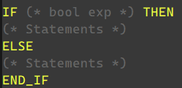
When the expression after IF is TRUE or 1 at the end, the description after IF will be operated immediately, otherwise the description after ELSE will be operated.
EX:
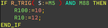
If M5 is Rise Trigger, and M88 is TRUE (1) , R100 = 10, and R10 = 12
Use ELSEIF if there are multiple comditions.
EX:
3-6-2 For Loop

Parameters:
(*Reg*):Counter register
Repeat the statement from FOR to END_FOR until the counter register reaches the target value.
Each time it is repeated, an incremental value or decremental value is added to the target value
(*Start*):Initial value
(*End*):Target value
(*< inc >*):Incremental value or decremental value
(*Statements*):Program to be executed in a loop
P.S. The BY field can be omitted (the default is 1) as shown below

|
Counter register |
Initial value |
Target value |
Incremental value or decremental value |
|
|
Single word |
○ |
○ |
○ |
|
|
Double word |
○ |
|||
|
Constant |
○ |
○ |
○ |
P.S. If the loop count is incrementing, then initial value < target value.
If the loop count is incrementing, then initial value > target value.
EX:
FOR DR0:=R2 TO R4 BY 2 DO //DR0 from R2, R2+2, R2+4,….etc, until it reaches to R4
R10++; // DR0=R4,R10=R0+(R4-R2)/2
END_FOR
3-6-3 Case Of
Selection of Integer conditions:
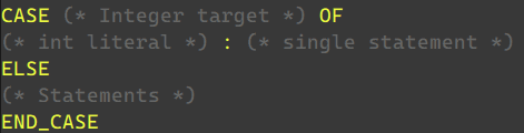
It will read the value of the target register, and run after the specified conditions are fully read: the following description .
If none are satisfied, the description after ELSE will be run
Conditions only support integer constants or constants within the range .. symbols
EX:
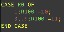
R0 = 1 //R100 = 10
//3, 4, 5, 6, 7, 8, 9 ,R100 = 11
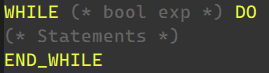
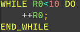
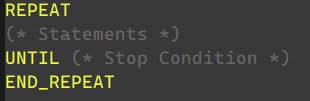
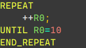
3-6-4 WHILE LOOP & REPEAT
Repeat the run description until the condition is (not) met
WHILE LOOP:
EX:
REPEAT:
EX:
NOTICE: Because of the logic of hardware running, if the WHILE does not jump out of the loop for a long time, the PLC device will not be able to handle other IO states, resulting in system errors. Users should be careful when using it.
3-6-5 BREAK / EXIT
In the loop situation of FOR, WHILE, REPEAT, you can leave the loop early with BREAK or EXIT at the appropriate time
EX:
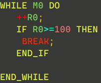
When R0 is greater than or equal to 100, it will run BREAK and jump out of the WHILE loop.
NOTICE: Because of the logic of hardware running, if the WHILE does not jump out of the loop for a long time, the PLC device will not be able to handle other IO states, resulting in system errors. Users should be careful when using it.
3-6-6 LBL, JMP, CALL
The LBL command can achieve the same effect as LD FUN_65, with a Label of up to 6 ASCII characters.
EX:
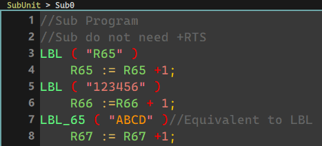
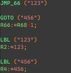
The keywords that can be used to call Label in the ST environment are as follows:
JMP_66, GOTO (for detailed description, please refer to FUN 66)
EX:
CALL,CALL_67 (for detailed description, please refer to FUN 67)
EX:
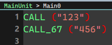
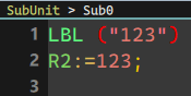
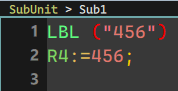
When using the Label function in a subroutine, the LBL instruction combined with RETURN will have different results.
EX:
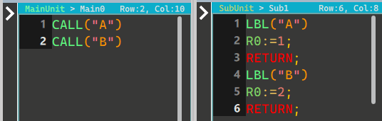
R0=2, because the Label of A.B is called at the same time and the result is RETURN.
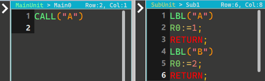
R0=1, because only the Label of A is called, and the result is RETURN
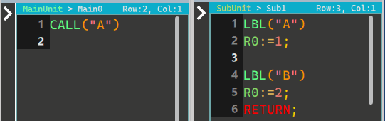
R0=2, because the Label of A is called, but RETURN is after the Label of B
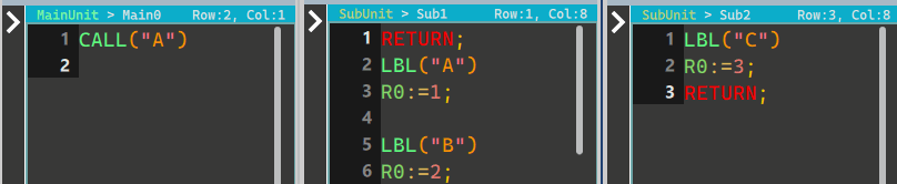
R0=3, because the Label of "Sub-unit 0" A is called, but RETURN is after the Label of "Sub-unit 1" C (special attention is required)
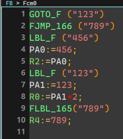
If you need to use tags in the FCM environment, you need to use the LBL_F、FLBL_165 instructions.
The Label keyword can only be called in FCM
GOTO_F (Label that can only be used in FB)
FJMP_166
EX:
1-7 Variables and Data Type
In the programming language, the use of variables and data types are an important part. In order to ensure that variables have typed characteristics, it is convenient for programmers to view and debug. ST uses Tag (Global, Local) to give variables a specific type.
The following introduces the data types and usage supported by ST.
|
Precautions If the operation result exceeds the value range that the data type can handle, the correct result (numeric value) will not be reflected in subsequent processing. The data type of the operation object variable should be converted in advance into a data type within the range that can process the operation results. |
Tag creation example
Labels are divided into global labels and regional labels. The label name created by the global label cannot be shared with the regional label. It is a label name that can be shared by the entire project. The label name created by the regional label can use the same name between different main programs, sub-programs, and Fcm programs without affecting each other (but the addresses must be different).
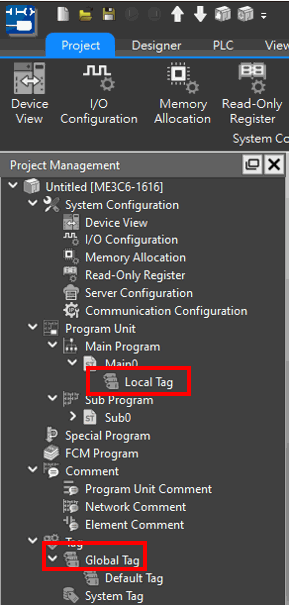
In order to cooperate with program operations of different data types, the following will demonstrate how to create different types of labels.
The Rx.Dx register is defaulted to INT16, and the DRx.DDx register is defaulted to INT32 integer variable.
EX
Double-click to select the Global Tag->Add new Tag
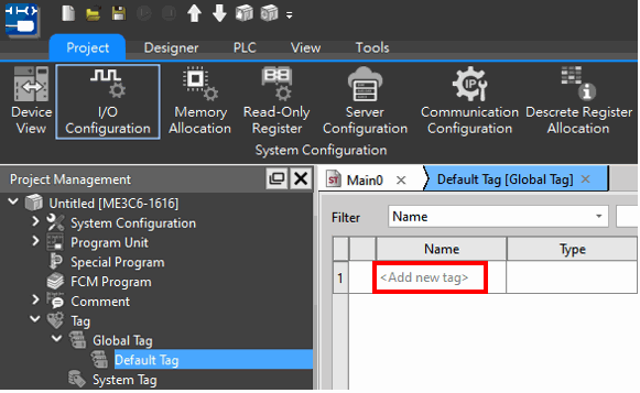
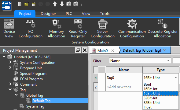
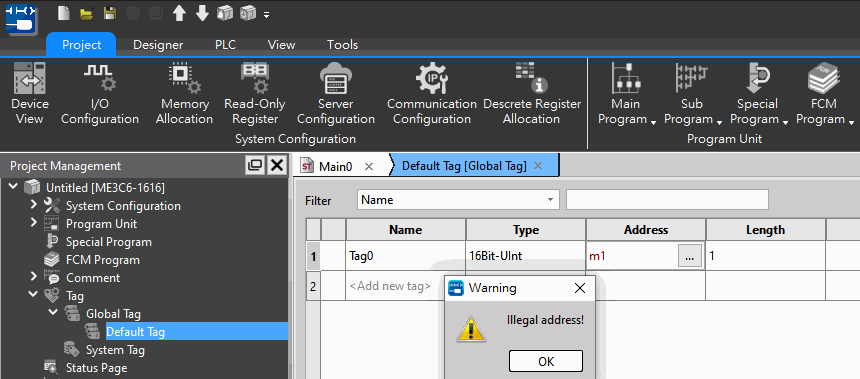
If the selected address and data type are not supported, a reminder will pop up to block it.
3-7-1 Bool / Bit
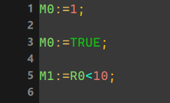
As long as the data represented is a bit or a value comparison operation (ex. <, >, <> … etc.), these results are all Bool (Bit) type, and 0 or 1, TRUE, FALSE can be used here accepted as a constant representing type Bool.
Among them, the switch of the relay is also represented by Bool/Bit ( ex. M0, X0, Y0…etc).
EX:
3-7-2 Integer Type
There are four integer types of ST: INT16, UINT16, INT32, UINT32
|
Type |
Description |
|
INT16 |
16-bit integer |
|
UINT16 |
16-bit positive integer |
|
INT32 |
32-bit integer |
|
UINT32 |
32-bit positive integer |
If a 16-bit register position (ex. R0, R1..etc) is used, the system will default to INT16 data type to process; if it is a 32-bit register (ex. DR0, DR2… etc), it will be seen as INT32
.
3-7-3 Floating Point
Floating-point defined for IEEE-754.
For ST operations on floating point, it is necessary to generate the corresponding Tag first, so that the system can know which variable refers to the register position representing a floating point.
Among them, when using floating-point operations, there will be some defaulted implicit behaviors. The descriptive example is in the figure below:
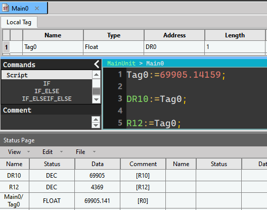
Line 1: Indicates that the floating point value of label 0 is assigned to 69905.14159
Line 3: Indicates converting the floating point value of label 0 into an int32 integer value
And there is a position of DR10, and the decimal point will be removed.
(ex. Tag 0 is 69905.141, then the DR10 content is 69905)
Line 5: Indicates that the floating point value of label 0 will be converted into an int16 integer value.
And there is a position of R12, the integer value exceeding int16 and the decimal point will be removed.
(ex. Tag 0 is 69905.141, then R12 content is 4369)
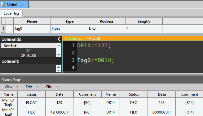
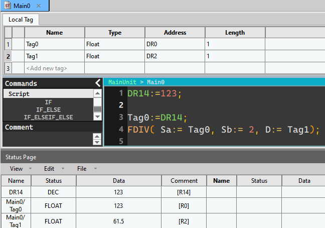
Line 2: DR14 (INT32) is converted into a floating-point data type and stored in the label 0
(The digital representation of observable floating point numbers is different from that of integers and can be used as Fun 200 I -> F)
EX:
3-7-4 Constant
The table below shows the ST-supported constant types:
|
Type |
Format andnd Sample |
|
Bool (Bit) |
0, 1, TRUE, FALSE ——————————————- M0:=1; M0:=TRUE; |
|
Integer |
Integer: R0:=1; R0:=-10; Binary: 2# followed by the value of 0,1, underscores can be used to divide groups R0:=2#1111_0000; Octal: 8# followed by the value, underscores can be used to divide groups R0:=8#243; Hexadecimal: 16# followed by the value, underscores can be used to divide groups 0x followed by the value, underscores can be used to divide groups |
|
Scientific Tag |
Tag_FlR100:=1E3; //1000 Tag_FlR100:=1.2E+3; //1200 Tag_FlR100:=1E-3; //0.001 |
|
Unit Symbol |
G: 1e+9 M: 1e+6 K,k: 1e+3 m: 1e-3 u: 1e-6 n: 1e-9 —————————————– DR0:=1G; R0:=1K; R0:=1k; DR0:=1M; Tag_FlR100:=1m; Tag_FlR100:=1n; Tag_FlR100:=1u; |
|
String (Currently only the Label command can be used) |
Use ASCII string quoted by“ symbol —————————————– LBL ( "my_lab" ) |
1-8 Using PLC Register and Memory
In addition to using the created Tag to call the corresponding register, users can also directly enter the name of the register to perform operations or flow control, as long as the data type of the register is single word 16bit —> INT16 double word 32bit —> INT32
EX:
R29:=100;
V:=19; // index register
R200:= R10V+100; R200=200
Among them, the special T and C bits will only have the characteristics of bit or int according to the logic of the program
EX:
/// T1 indicates bit type
/// whether timeout
IF T1 THEN
R10:=20;
/// T1 represents the value of current timer
/// is the integer of int16
ELSEIF T1>100 THEN
R10:=30;
END_IF
///At this time, T1 will be regarded as a Bit type for negation
M0:=NOT T1;
1-9 Calling System Built-In Functions
The description of the built-in functions will be shown as below:
<Function> ( <Parameter 1> := <Input Parameter 1> , ….);
Like the ladder diagram, ST has some built-in functions for users to call, which will appear in the toolbox column on the right.
You can drag and drop from the toolbox or double-click the field and it will be added to the text.
When calling, the order of parameters can be changed at will, but it cannot be omitted.
Unless some special values are allowed to be omitted
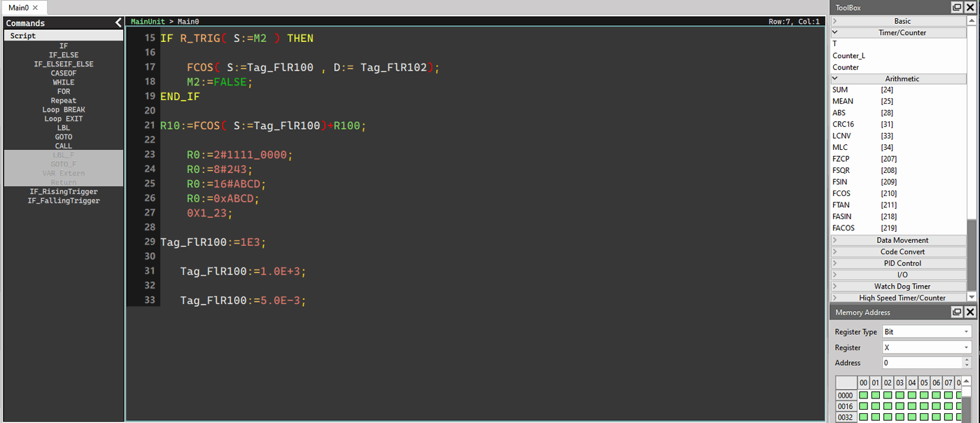
Some of the functions will be divided into 32 bit mode (the default is 16 bit mode), you will need to add D_ in front of the function to clearly indicate that the function is in 32 bit mode. You can directly input D_ and the corresponding will appear the list of hints indicates those with 32 bit mode.
EX: Binary code conversion to Gray code
Error conversion Correct conversion
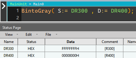
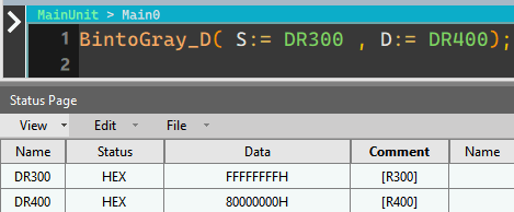
Most functions are executed as soon as they are called. If you want to execute the action only once after the condition is met, please refer to the writing method.
EX:
IF R_TRIG( S:="condition" ) then
"Function"
END_IF
!Note! The "Motion Basic"."Motion Mode1". "Motion Mode2". "Motion Mode3" functions in the toolbox are only executed once unless the conditional state changes.
For the detailed parameter content of each call function, please refer to FUN file. The following is an introduction for different FUN.
3-9-1 Timer
Prototype:
Timer( Trigger:= (* Trigger Bit Rising Edge ->ON, Falling Edge ->OFF *),
T:= (* Timer 0~1023 *),
PV:= (* preset value (0~32767) *),
IsTimeout=> (* time out bit *));
Parameter:
Trigger (bool) : Rising Edge Start Timer
Falling Edge Stop run
T (int) : Integer from 0~1023 represent Timer T0~T1023
PV (int) : Timer threshold
IsTimeout (bool) : Whether Timer reaches the target
For detailed description, please refer to corresponding LD Timer files.
3-9-2 Counter / Counter_L
There are two groups of Counter functions here, so that users can easily distinguish whether they are currently calling the counter of single word (Counter) or the version of double words (Counter_L)
Prototype:
Counter( Pulse:= (* Pulse Signal *),
Clr:= (* CLR Signal *),
C:= (* counter number (0~1023) *),
PV:= (* Preset value (Single Word 0~65535) *),
IsUp=> (* Counter Is Up *));
Counter_L( Pulse:= (* Pulse Signal *),
Clr:= (* CLR Signal *),
C:= (* counter number (1024~1279 Long counter) *),
PV:= (* Preset value (Double Words) *),
IsUp=> (* Counter Is Up *));
Parameter:
Pulse (bool) : Off->On Count once //M0,M9129…etc
Clr (bool) : Whether to clear counter
C (int) : Counter id 0~1279
PV (int) : Counter Default value
IsUp (bool) : Whether Counter reaches the target //M0,C0…etc
3-9-3 R_TRIG / F_TRIG
Rising Edge and Falling Edge’s detecting function
Prototype:
Mode 1:
R_TRIG( S:= , D=> )
F_TRIG( S:= , D=> )
Mode 2:
R_TRIG( S:= )
F_TRIG( S:= )
Implied with Return Value D
Parameter:
S (bool) : Rising / Falling Edge Detecting source
D (bool) : Detecting result
Example:
Mode 1: R_TRIG(S:=M0, D:=M5);
Mode 2:
IF R_TRIG(S:=M0) THEN
++R100;
END_IF
3-9-4 TARESUB and TAREZEOFFSET
These two functions are derived from the original FUN258. Removed from Tare Weight Deduction Command mode .
For detailed parameter settings from MODCONF, please refer to the original FUN258 file.
Splitting into two independent functions is also a function that is convenient for users to call at a glance when writing.
Prototype
TAREZEOFFSET( EN:= , MD:= , ID:= , CH:= , WR:= , ERR=> , DN=> )
TARESUB( EN:= , RST:= , ID:= , CH:= , SB:= , ERR=> )
1-10 Functions with multiple calling modes
Such as the trigger detection instructions in the previous chapter 3-9-3. These instructions support two types, one is a direct complete call, and the other is to omit the register location (D) where the result is stored. The following table is is a function that currently has this feature.
|
Function |
Parameter specialized in Return |
Function Format |
|
FSQR |
D |
FSQR(S:= ,D:= ) |
|
FSIN |
D |
FSIN(S:= ,D:= ) |
|
FCOS |
D |
FCOS(S:= ,D:= ) |
|
FTAN |
D |
FTAN(S:= ,D:= ) |
|
FASIN |
D |
FASIN(S:= ,D:= ,MD:= ) |
|
FACOS |
D |
FACOS(S:= ,D:= ,MD:= ) |
|
R_TRIG |
D |
R_TRIG(S:= ,D:= ) |
|
F_TRIG |
D |
F_TRIG(S:= ,D:= ) |
|
ItoF |
D |
ItoF(S:= ,D:= ) |
|
FtoI |
D |
FtoI(S:= ,D:= ) |
That is to say, the parameters of the above-mentioned functions with return characteristics can be omitted when calling again, and directly use another parameter to undertake or directly operate.
EX:
Without omission:
FSIN(S:=Tag_Float_DR100, D:=Tag_Float_DR102);
Omit the return parameter: (Since values and representative results are returned, some four arithmetic operations or conditional judgments can be directly introduced)
Tag_Float_DR200 := FSIN(S:=Tag_Float_DR100) + FSIN(S:=Tag_Float_DR102);
1-11 Multi-cycle instruction
The following instruction list shows the instructions operating continuously in the background. The way to use it is to place it outside the IF loop to execute it every scan cycle, and determine the operating state of the function according to the EN signal.
As the example shown below:
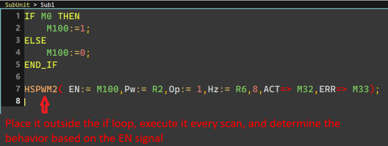
Because these instruction classes are called, the execution time usually exceeds one scan cycle.
The following table shows the Multi-cycle instruction currently included:
|
Function |
Function ID |
|
LCNV |
33 |
|
MLC |
34 |
|
TPCTL2 |
99 |
|
RAMP2 |
98 |
|
HSPWM |
139 |
|
HSPSO |
140 |
|
MPARA |
141 |
|
PSOFF |
142 |
|
PSCNV |
143 |
|
MPG |
148 |
|
ModBUS |
150 |
|
CLINK |
151 |
|
ReadWriteFileReg |
160 |
|
WriteSDMem |
161 |
|
ReadSDMem |
162 |
|
PID2 |
38 |
|
DBUF |
115 |
|
ICA |
137 |
|
ICF |
138 |
|
NCR |
152 |
|
CMCTL |
156 |
|
ME_START |
176 |
|
ME_SYSSTOP |
177 |
|
ME_HOME |
178 |
|
ME_POS |
179 |
|
ME_JOG |
180 |
|
ME_CHGPRM |
181 |
|
ME_PAUSE |
182 |
|
ME_RESUME |
183 |
|
ME_HALT |
184 |
|
ME_RSTALM |
185 |
|
ME_STOP |
186 |
|
ME_SYSINIT |
187 |
|
ME_RCPR |
188 |
|
ME_RCPW |
189 |
|
ME_CAMR |
191 |
|
ME_CAMW |
192 |
|
ME_GEAR_IN |
193 |
|
ME_VEL_CTL |
194 |
|
ME_TOR_CTL |
195 |
|
ME_CAM_GEN |
196 |
|
ME_AXI_MOV |
197 |
|
ME_SET_MAP |
198 |
|
ME_VIR_AXI |
235 |
|
HSPWM2 |
144 |
|
TARESUB |
|
|
TAREZEOFFSET |
1-12 Enable/Disable Interrupt and Special Instructions
Please refer to FUN 145, 146

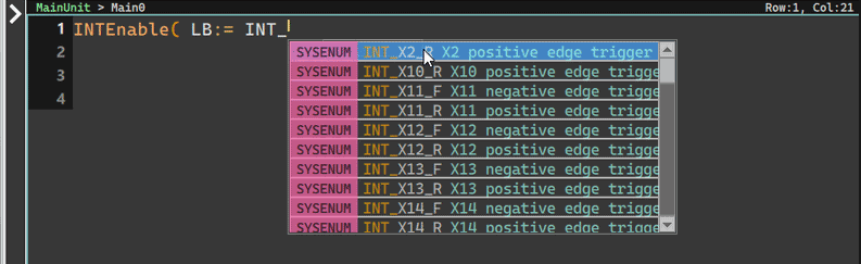
LB parameters input integers from 1 to 49, corresponding to the types of interrupts.
For all supported types, please refer to the chapter of special instructions.
|
INT No. UserView |
Interrupt Source |
Priority
|
Interrupt Label
|
Condition
|
Note
|
|
1 |
Build-in Digital Inputs |
X0+I (INT0+) |
X0 positive edge trigger |
The software high speed counter HSC4~HSC7 can be assigned as the trigger source of any interrupt X0~X15. Therefore, the interrupt priority of the software high speed counter depends on the priority of X0~X15. |
|
|
2 |
X0−I (INT0-) |
X0 negative edge trigger |
|||
|
3 |
X1+I (INT1+) |
X1 positive edge trigger |
|||
|
4 |
X1−I (INT1-) |
X1 negative edge trigger |
|||
|
5 |
X2+I (INT2+) |
X2 positive edge trigger |
|||
|
6 |
X2−I (INT2-) |
X2 negative edge trigger |
|||
|
7 |
X3+I (INT3+) |
X3 positive edge trigger |
|||
|
8 |
X3−I (INT3-) |
X3 negative edge trigger |
|||
|
9 |
X4+I (INT4+) |
X4 positive edge trigger |
|||
|
10 |
X4−I (INT4-) |
X4 negative edge trigger |
|||
|
11 |
X5+I (INT5+) |
X5 positive edge trigger |
|||
|
12 |
X5−I (INT5-) |
X5 negative edge trigger |
|||
|
13 |
X6+I (INT6+) |
X6 positive edge trigger |
|||
|
14 |
X6−I (INT6-) |
X6 negative edge trigger |
|||
|
15 |
X7+I (INT7+) |
X7 positive edge trigger |
|||
|
16 |
X7−I (INT7-) |
X7 negative edge trigger |
|||
|
17 |
Hardware Time Tick |
3 |
STM0I |
Interval from 1ms~60000ms |
Tick unit 1ms,Value=1~60000 |
|
18 |
3 |
STM1I |
Interval from 1ms~60000ms |
||
|
19 |
3 |
STM2I |
Interval from 1ms~60000ms |
||
|
20 |
3 |
STM3I |
Interval from 1ms~60000ms |
||
|
21 |
3 |
LTM0I |
Interval from 10ms~60000ms |
Tick unit 10ms,Value=1~6000 |
|
|
22 |
3 |
LTM1I |
Interval from 10ms~60000ms |
||
|
23 |
3 |
LTM2I |
Interval from 10ms~60000ms |
||
|
24 |
3 |
LTM3I |
Interval from 10ms~60000ms |
||
|
25 |
HST |
1 |
HST0I |
Interval from 0.1ms to 6000ms |
Tick uint 100us,Value=1~60000 |
|
26 |
1 |
HST1I |
Interval from 0.1ms to 6000ms |
||
|
27 |
1 |
HST2I |
Interval from 0.1ms to 6000ms |
||
|
28 |
1 |
HST3I |
Interval from 0.1ms to 6000ms |
||
|
33 |
HSC |
2 |
HSC0I |
Interval from HSC0 to (CV=PV) |
|
|
34 |
2 |
HSC1I |
Interval from HSC1 to (CV=PV) |
||
|
35 |
2 |
HSC2I |
Interval from HSC2 to (CV=PV) |
||
|
36 |
2 |
HSC3I |
Interval from HSC3 to (CV=PV) |
||
|
37 |
2 |
HSC4I |
Interval from HSC4 to (CV=PV) |
||
|
38 |
2 |
HSC5I |
Interval from HSC5 to (CV=PV) |
||
|
39 |
2 |
HSC6I |
Interval from HSC6 to (CV=PV) |
||
|
40 |
2 |
HSC7I |
Interval from HSC7 to (CV=PV) |
||
|
66 |
Build-in Digital Inputs (MA Series) |
X8+I (INT8+) |
X8 positive edge trigger |
The software high speed counter HSC4~HSC7 can be assigned as the trigger source of any interrupt X0~X15. Therefore, the interrupt priority of the software high speed counter depends on the priority of X0~X15. |
|
|
67 |
X8−I (INT8-) |
X8 negative edge trigger |
|||
|
68 |
X9+I (INT9+) |
X9 positive edge trigger |
|||
|
69 |
X9−I (INT9-) |
X9 negative edge trigger |
|||
|
70 |
X10+I (INT10+) |
X10 positive edge trigger |
|||
|
71 |
X10−I (INT10-) |
X10 negative edge trigger |
|||
|
72 |
X11+I (INT11+) |
X11 positive edge trigger |
|||
|
73 |
X11−I (INT11-) |
X11 negative edge trigger |
|||
|
74 |
X12+I (INT12+) |
X12 positive edge trigger |
|||
|
75 |
X12−I (INT12-) |
X12 negative edge trigger |
|||
|
76 |
X13+I (INT13+) |
X13 positive edge trigger |
|||
|
77 |
X13−I (INT13-) |
X13 negative edge trigger |
|||
|
78 |
X14+I (INT14+) |
X14 positive edge trigger |
|||
|
79 |
X14−I (INT14-) |
X14 negative edge trigger |
|||
|
80 |
X15+I (INT15+) |
X15 positive edge trigger |
|||
|
81 |
X15−I (INT15-) |
X15 negative edge trigger |
|||
|
82 |
MQ model DI Plug-in |
X16+I (INT15+) |
X16上沿觸發 |
||
|
83 |
X16−I (INT15-) |
X16 下沿觸發 |
|||
|
84 |
X17+I (INT15+) |
X17上沿觸發 |
|||
|
85 |
X17−I (INT15-) |
X17 下沿觸發 |
|||
|
86 |
X18+I (INT15+) |
X18上沿觸發 |
|||
|
87 |
X18−I (INT15-) |
X18 下沿觸發 |
|||
|
88 |
X19+I (INT15+) |
X19上沿觸發 |
|||
|
89 |
X19−I (INT15-) |
X19 下沿觸發 |
|||
|
90 |
X20+I (INT15+) |
X20上沿觸發 |
|||
|
91 |
X20−I (INT15-) |
X20下沿觸發 |
|||
|
92 |
X21+I (INT15+) |
X21上沿觸發 |
|||
|
93 |
X21−I (INT15-) |
X21下沿觸發 |
|||
|
94 |
X22+I (INT15+) |
X22上沿觸發 |
|||
|
95 |
X22−I (INT15-) |
X22 下沿觸發 |
|||
|
96 |
X23+I (INT15+) |
X23上沿觸發 |
|||
|
97 |
X23−I (INT15-) |
X23 下沿觸發 |
1-13 Variable names with special meanings
- Timer, Counter
T0~TN, C0~CN
In the ST environment, these two variables are given the characteristics of Bool and the characteristics of Integer.
EX:
R0:=T1;
//The currently calculated value of Timer1 will be stored in R0(Integer)
M0:=T1;
// Will save the status of whether Timer1 is currently running to M0 (Bool)
M3:=C1>10;
// Will determine whether Counter 1 counts more than 10
IF R_TRIG( T1 ) THEN
/// When Timer1 changes from 0 to 1 (the moment it starts running), it will be executed
END_IF
- Interrupt (Enum)
Originally, only constants could be input for Enable/Disable interrupts. In order to improve the readability of the program, it was modified to allow the input of system default Enum parameters. If you type INT_, the corresponding series of available Enums will be displayed.
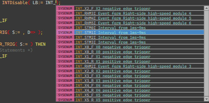
EX:
IF M2 THEN
INTEnable( LB:= INT_STM1I);
ELSE
INTDisable( LB:= INT_STM1I);
END_IF
- High-speed counting Enum “HSC_” Prefix
Call related high-speed instructions such as
HSCTR( CN:= (* 0~7 *));
HSCTW( S:= , CN:= , D:= );;
Among them, the parameter expressions of CN, and D support constant integers. For the convenience of reading, Enum starting with HSC_ is also imported.
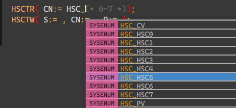
Make programs more readable
EX:
HSCTR( CN:= HSC_HSC0(* 0~7 *));
HSCTW( S:=R0 , CN:=HSC_HSC0 , D:=HSC_PV );
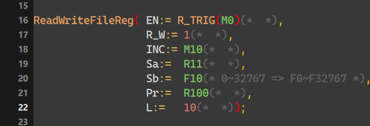
- File Register Enum F0~F32767
For the Sb parameter of FUN 160, in addition to using 0~32767, you can use the Enum of F0~F32767 to represent the corresponding position.
EX:
1-14 Calling FCM Function
The calling method is similar to calling system function, while the functions are built by users themselves.
The built functions will be placed in FCM List in the command column on the left.
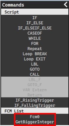
Users can double-click the section to insert the selected function to the text.
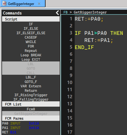
FCM can specify a Return Value, which can be call directly when programming.
EX:
FCM:
Calling side:
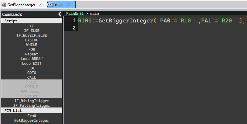
In this way, some temporarily unnecessary variable declarations can be reduced in a timely manner.
1-15 Function notes
Whether it is built-in call system or FCM, they all have the following common characteristics:
A. Calling method:
1. Enter the complete parameter name
2. Omit parameter names
3. Output parameters (=>) can be directly ignored and not passed.
example:
Take the R_TRIG function as an example
Complete performance: R_TRIG( S:= M0, D=>M1);
If you use parameters to bring it in, it is not allowed to follow the preset order.
The above function can be changed to
R_TRIG( D=>M1, S:= M0 );
R_TRIG( D=>M1);
All are legal inputs
Omit parameter name: R_TRIG(M0, M1);
Those with Return effect or output do not need to be passed :
R_TRIG( S:= M0 );
R_TRIG( M0 );
Those with the Return attribute can be mixed with other variables or descriptive sentences.
IF R_TRIG(M0) THEN
//// some statements
END_IF
M10:= R_TRIG(M0) AND R_TRIG(M1);
! Note! Calling methods with parameters and without parameters cannot be mixed. For example:
R_TRIG(S:=M0, M1);
R_TRIG(M1,D:=M2);
Both of the above are illegal inputs.
Tip: press ← → to switch chapters, Ctrl+K to search