Summary of M-PLC Motion Control Unit
This section describes the function and overview of the M-PLC Motion Control Unit. In design, the M-PLC provides the communication-based EtherCAT axial motion control function. It can be used to control the operation of maximum 16 axes. In the meantime, it also provides the impulse motion control for a number of 8 axes. In the aspect of programming, the M-PLC provides the motion control required for calling the ladder diagram as well as the motion control calling required for the Motion Flow.
*The 32-Axis EtherCAT Motion Control is still being planned, please refer to FATEK official website for related information and manual.
1-1 Motion Unit Function Diagram
The M-PLC Motion Control Unit can issue the motion command to the servo drive while providing the axis control related functions such as position control, speed control and synchronizing control.
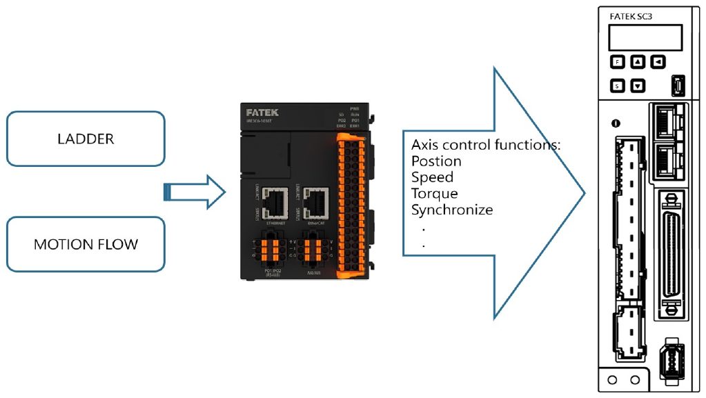
Program Function:
In terms of programming function, the M-PLC program provides conventional ladder diagram related program design and the Motion Flow related motion flow block required for the motion control.
Axis Control Function:
With the axis control function, it allows the user to output the action commands such as position control, speed control or synchronizing control for the connected axis servo and the created servo.
Servo EtherCAT I/O Function:
Through the EtherCAT communication, the user will be allowed to read the servo I/O status such as HOME signal and limit signal, etc.
1-2 Axis Control Function and Reference
Provided below are the axis motion control functions and the references
|
Axis motion control function |
Reference |
|
HOME Return |
|
|
Position Control |
|
|
Speed Control |
|
|
Torque Control |
|
|
Synchronous Control |
|
|
Interpolation Control |
|
|
JOG Control |
In addition to the aforesaid axis functions reference, it also allows the user to use the following functions:
|
Function Unit |
Reference |
|
Special Motion Register and Relay |
|
|
EtherCAT Function |
|
|
Axis Parameters and Point Parameters |
|
|
Ladder Command |
|
|
Motion Flow Block |
|
|
Motion Parameter Mapping Table |
|
|
Test Run |
1-3 Appearance of the PLC Unit
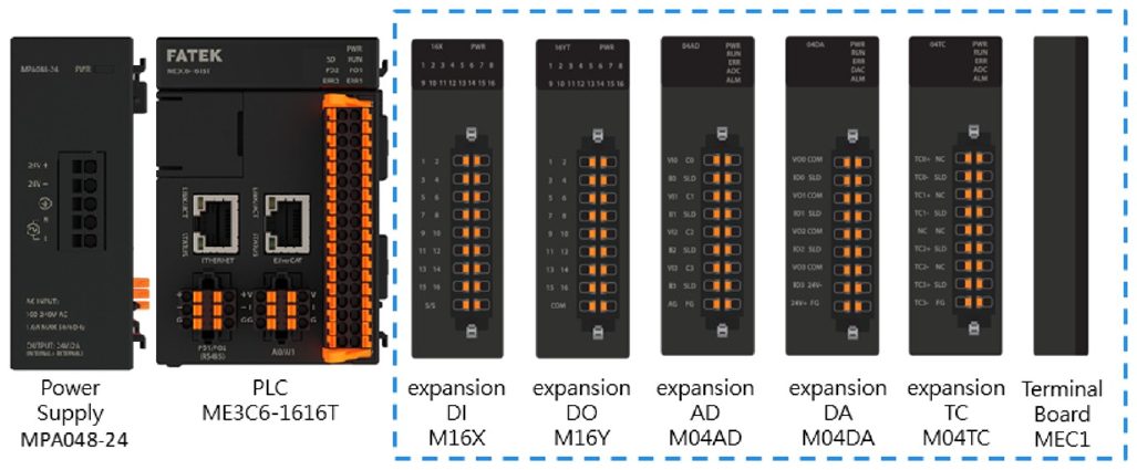
Described below are the unit hardware interfacing port between M-PLC units and the indicator status, as per the M-PLC Unit indicated below. The left-hand side port is provided for connecting to the power module and communication module, and the right-hand side port is designed for connecting to the AIO, DIO and temperature module, etc. Further, the right-hand side should also be provided with a terminal module for using as the terminal end.
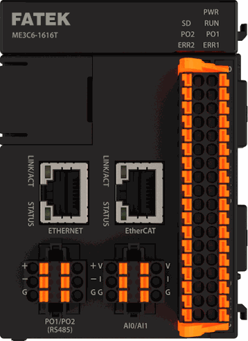
Indicated below are the M-PLC unit related ports:
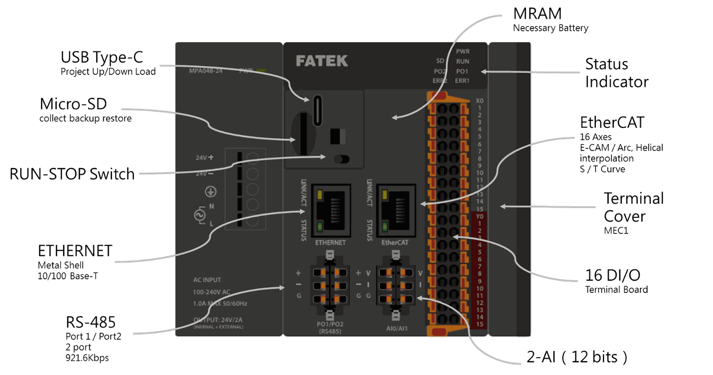
Indicated below is the M-PLC Power Module:
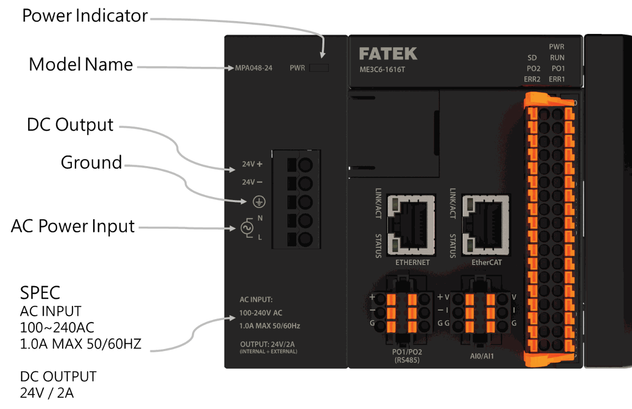
The M-PLC also provides the extension function of expanding the right-hand side module. It allows the user to apply such function to other equipment for expanding the AIO/DIO/temperature modules, as per the figure below:
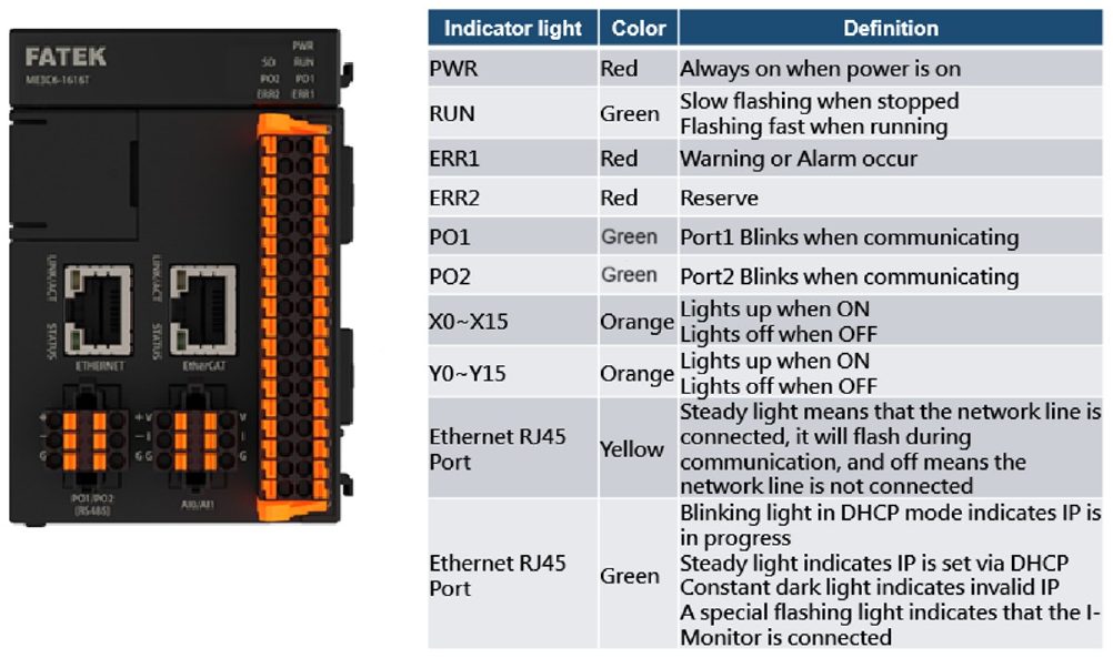
Described below are the M-PLC status indicators:
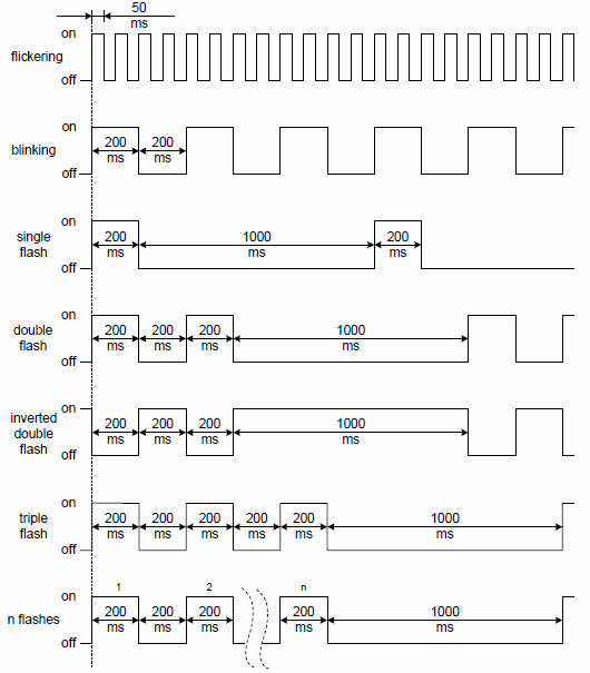
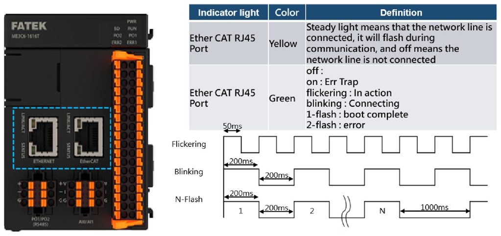 `
1-4 Action before M-PLC Position Control
Before executing the position control with the M-PLC, the user is required to execute the following basic start-up steps:
|
Step |
Action |
Remark |
|---|---|---|
|
1 |
Installation/Wiring Wiring installation of M-PLC, SC3 EtherCAT servo and external devices. |
|
|
2 |
Install the M-PLC editing software: UperLogic. |
Please refer to Software User Manual |
|
3 |
Set [Motion Axis Link] and [Motion Axis Parameter] with Uperlogic. |
Please refer to Chapter 4 |
|
4 |
Programming and use Fun187 to initialize SC3 EtherCAT Servo. |
Please refer to Section 6-1 |
|
5 |
Programming and use special register $ALL_SERVO_ON (M10520) to enable SC3 EtherCAT Servo. |
Please refer to Chapter 2 |
|
6 |
Programming and use Ladder and Motion Control Flow to execute motion control. |
Please refer to Chapter 5-7 |
|
7 |
Downloading projects to M-PLC. |
Enabling download through USB or Network. |
|
8 |
Starting test run. |
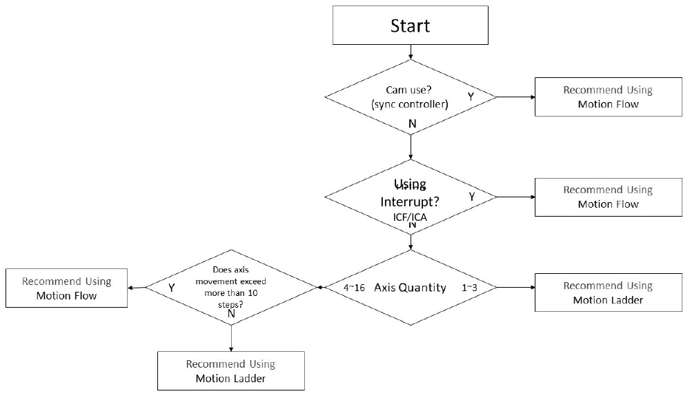
Ladder Diagram and Selection of Motion Control:
Tip: press ← → to switch chapters, Ctrl+K to search