Point Table and Point Parameter
This section describes the setting method and the parameters required for the motion point. The information of the Motion Flow motion point such as target position/max. speed/ acceleration/deceleration and acceleration type are set according to the point table and the point parameters. When using the PLC to change the content of the point table and point parameter setup value, please refer to Chapter 8: Motion Parameter Mapping Table.
5-1 Motion Point Setting Interface
The setup interface required for setting the motion point is provided by the FATEK project editing software UperLogic, as per below:
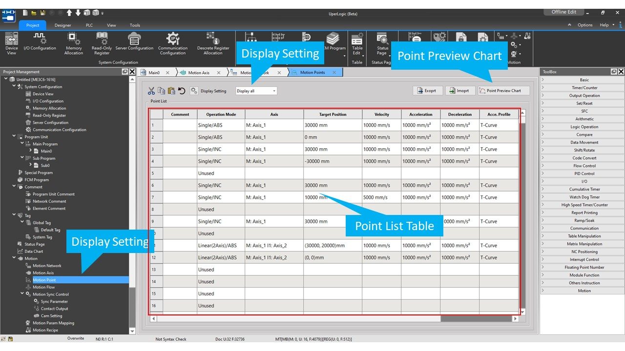
Corresponding upper limit is created for the capacity of the motion point when using the selected PLC.
|
PLC Model |
Motion Point table size |
|---|---|
|
MXXC1 |
128 points |
|
MXXC2 |
192 points |
|
MXXC3 |
256 points |
|
MXXC4 |
512 points |
|
MXXC5 |
512 points |
|
MXXC6 |
1024 points |
Introduction of Point Data Setting:
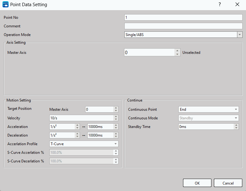
Point Number: The number of the point that will be executed for the Ladder or the process.
Operation mode:
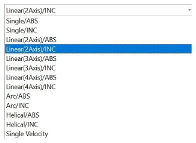
Master Axis: The axis to be operated.
If multi-axis interpolation is selected as the axis mode, then UI will display the following:
Interpolation Axis 2: The Interpolated Axis 2 to be operated.
Interpolation Axis 3: The Interpolated Axis 3 to be operated.
Interpolation Axis 4: The Interpolated Axis 3 to be operated.
Target Position:
Master Axis: The Master Axis target position represents the travel (relative)/position (absolute) that will be run by the axis.
Interpolation Axis 1: The target position of Interpolation Axis 1, which is determined according to the mode selected.
Interpolation Axis 2: The target position of Interpolation Axis 2, which is determined according to the mode selected.
Interpolation Axis 3: The target position of Interpolation Axis 3, which is determined according to the mode selected.
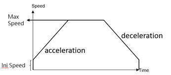
Speed: The exported speed or the maximum speed required for frequency movement. Such value cannot be reached if the distance is too short for acceleration to the maximum.
Acceleration: The acceleration required for increasing the initial speed to the desired value.
Deceleration: The acceleration required for decreasing the initial speed to the desired value.
Acceleration type: T-Curve / S-Curve
S Acceleration Curve percentage scope: 1%–100%
S Deceleration Curve percentage scope: 1%–100%
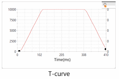
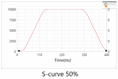
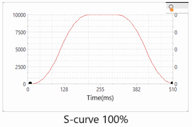
Continue Point: Set “End” or “Continue Point” (select the point data to be executed on the point table).
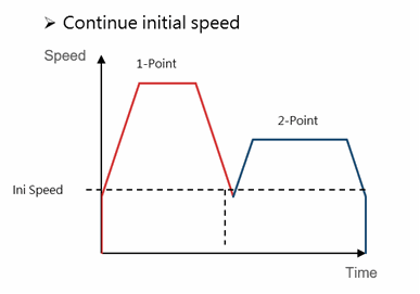
Continue Mode:
Standby: The “ms” duration that should be paused before moving to the next point after completing the operation at the current point.
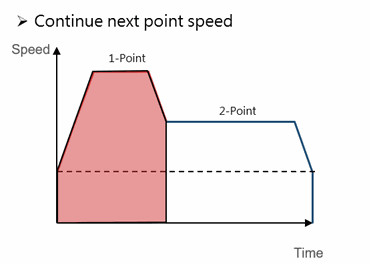
Continue next point speed: Moving to the next point after completing the acceleration or deceleration for such point.
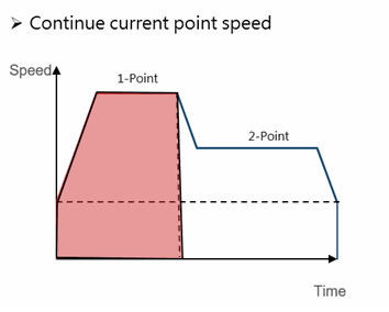
Continue current point speed: Moving to the next point through acceleration or deceleration after completing current speed.
Continue initial speed: Moving to the next point after reducing to the initial speed.
Standby time: The standby time when operating under Standby Mode (unit: ms).
5-2 Point Preview Picture
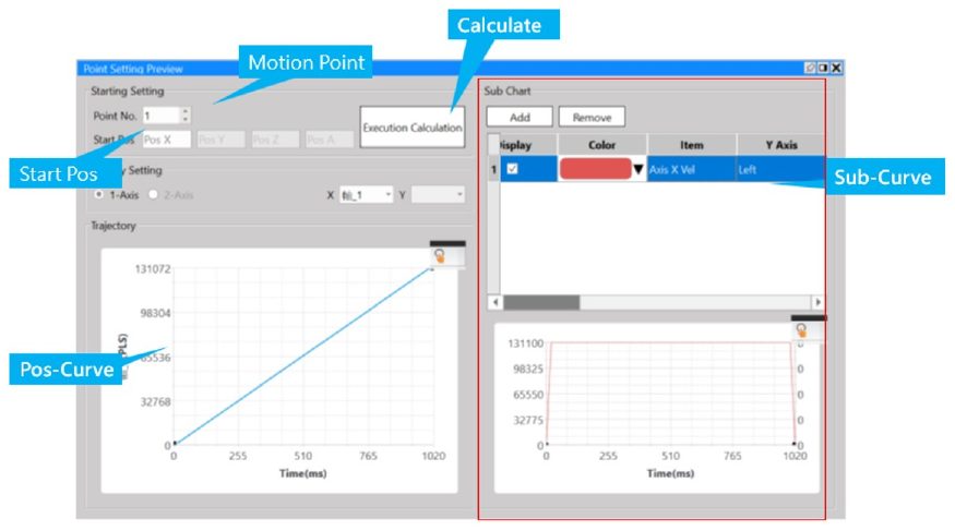
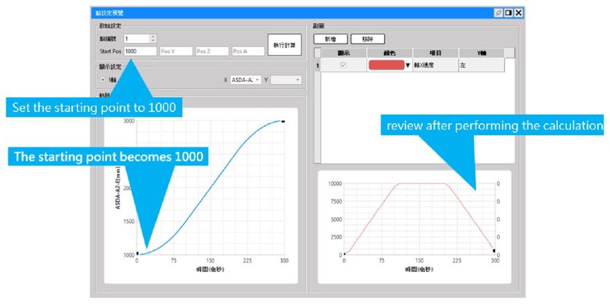
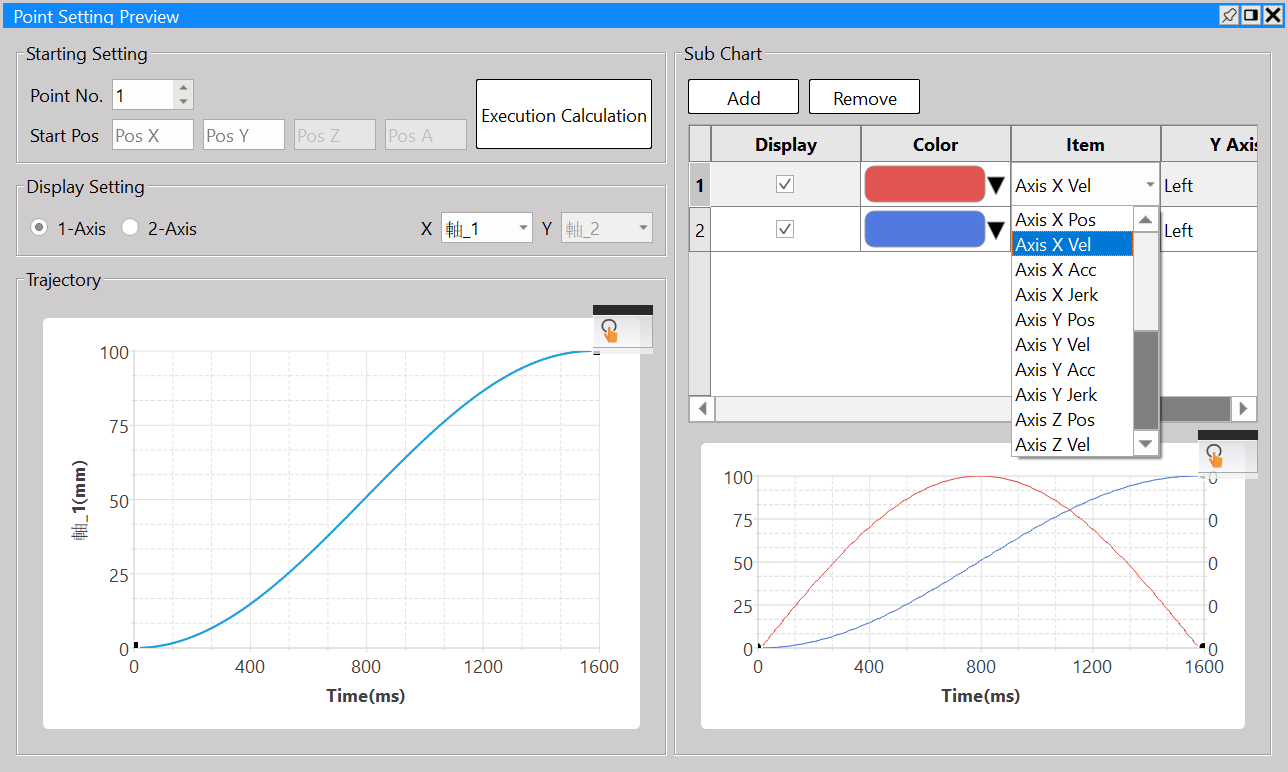
In Point Preview Picture, you may preview the track and the speed relating to the travel that will be set for the point parameter.
Example: Move Absolute Position 1000 to 3000.
In Point Preview Picture, you may preview the track and the speed relating to the travel that will be set for 2D.
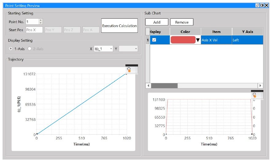
You may use the auxiliary picture to check the speed change of the axis.
Tip: press ← → to switch chapters, Ctrl+K to search